2009 MITSUBISHI ASX brake
[x] Cancel search: brakePage 194 of 368
NOTE
l The
combination of items shown on the dis-
play varies depending on the vehicle model. CAUTION
l
When display/indicator blinks, ASC is
operating,
which means that the road is
slippery or that your vehicle’s wheels are
beginning to slip. If this happens, drive
slower with less accelerator input.
l If the temperature in the braking system
continues to increase due to continuous
brake control on a slippery road surface,
the display/indicator will blink. To pre-
vent
the brake system from overheating,
the brake control of the traction control
function will be temporarily suspended.
The engine control of the traction control
function and normal brake operation will
not be affected. Park your vehicle in a
safe place. When the temperature in the
braking system has come down, the dis-
play/indicator
will be turned off and the
traction control function will start operat-
ing again.
NOTE l The display/indicator may turn on when
you
start the engine. This means that the bat-
tery voltage momentarily dropped when the
engine was started. It does not indicate a mal-
function, provided that the display goes out
immediately. l
When
a compact spare tyre has been put on
your vehicle, the gripping ability of the tyre
will be lower, making it more likely that the display/indicator will blink.
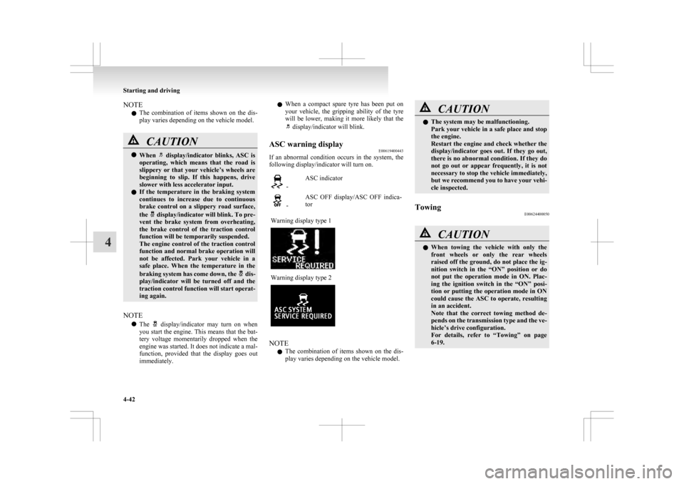
ASC warning display E00619400443
If an abnormal condition occurs in the system, the
following display/indicator will turn on. -
ASC indicator -
ASC OFF display/ASC OFF indica-
tor
Warning display type 1 Warning display type 2
NOTE
l The
combination of items shown on the dis-
play varies depending on the vehicle model. CAUTION
l
The system may be malfunctioning.
Park
your vehicle in a safe place and stop
the engine.
Restart the engine and check whether the
display/indicator goes out. If they go out,
there is no abnormal condition. If they do
not go out or appear frequently, it is not
necessary to stop the vehicle immediately,
but we recommend you to have your vehi-
cle inspected.
Towing E00624400050 CAUTION
l
When
towing the vehicle with only the
front wheels or only the rear wheels
raised off the ground, do not place the ig-
nition switch in the “ON” position or do
not put the operation mode in ON. Plac-
ing the ignition switch in the “ON” posi-
tion or putting the operation mode in ON
could cause the ASC to operate, resulting
in an accident.
Note that the correct towing method de-
pends on the transmission type and the ve-
hicle’s drive configuration.
For details, refer to “Towing” on page
6-19. Starting and driving
4-42
4
Page 195 of 368
Cruise control*
E00609101008
Cruise
control is an automatic speed control system
that keeps a set speed. It can be activated at about
40 km/h (25 mph) or more. CAUTION
l
When
you do not wish to drive at a set
speed, turn off the cruise control for safety.
l Do not use cruise control when driving
conditions will not allow you to stay at
the same speed, such as in heavy traffic
or on roads that are winding, icy, snow-
covered, wet, slippery, on a steep down-
hill slope.
l On vehicles with M/T, do not move the
gearshift lever to the “N” (Neutral) posi-
tion while driving at a set speed without
depressing the clutch pedal. The engine
will run too fast and might be damaged.
NOTE l Cruise
control may not be able to keep your
speed on uphills or downhills.
l Your speed may decrease on a steep uphill.
You may use the accelerator pedal if you
want to stay at your set speed.
l Your speed may increase to more than the
set speed on a steep downhill. You must use
the brake to control your speed. As a result,
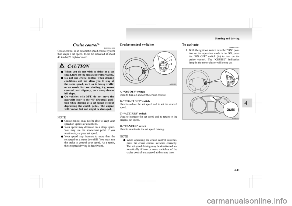
the set speed driving is deactivated. Cruise control switches
A- “ON OFF” switch
Used to turn on and off the cruise control.
B- “COAST SET” switch
Used
to reduce the set speed and to set the desired
speed.
C- “ACC RES” switch
Used to increase the set speed and to return to the
original set speed.
D- “CANCEL” switch
Used to deactivate the set speed driving.
NOTE
l When operating the cruise control switches,
press the cruise control switches correctly.
The set speed driving may be deactivated au-
tomatically if two or more switches of the
cruise control are pressed at the same time. To activate
E00609300957
1. With
the ignition switch is in the “ON” posi-
tion or the operation mode is in ON, press
the “ON OFF” switch (A) to turn on the
cruise control. The “CRUISE” indication
lamp in the meter cluster will come on. Starting and driving
4-43 4
Page 197 of 368
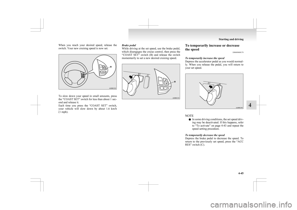
When you reach your desired speed, release the
switch. Your new cruising speed is now set.
To slow down your speed in small amounts, press
the
“COAST SET” switch for less than about 1 sec-
ond and release it.
Each time you press the “COAST SET” switch,
your vehicle will slow down by about 1.6 km/h
(1 mph). Brake pedal
While
driving at the set speed, use the brake pedal,
which disengages the cruise control, then press the
“COAST SET” switch (B) and release the switch
momentarily to set a new desired cruising speed. To temporarily increase or decrease
the speed
E00609600178
To temporarily increase the speed
Depress
the accelerator pedal as you would normal-
ly. When you release the pedal, you will return to
your set speed. NOTE
l In
some driving conditions, the set speed driv-
ing may be deactivated. If this happens, refer
to “To activate” on page 4-43 and repeat the
speed setting procedure.
To temporarily decrease the speed
Depress the brake pedal to decrease the speed. To
return to the previously set speed, press the “ACC
RES” switch (C). Starting and driving
4-45 4
Page 198 of 368
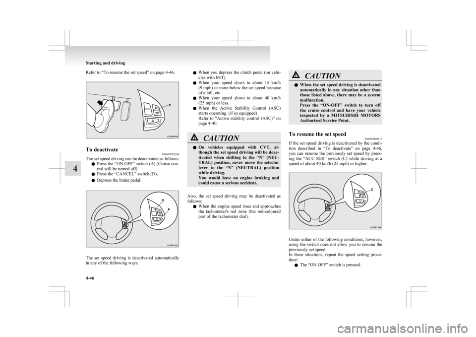
Refer to “To resume the set speed” on page 4-46.
To deactivate
E00609701206
The set speed driving can be deactivated as follows:
l Press
the “ON OFF” switch (A) (Cruise con-
trol will be turned off)
l Press the “CANCEL” switch (D).
l Depress the brake pedal. The set speed driving is deactivated automatically
in any of the following ways. l
When
you depress the clutch pedal (on vehi-
cles with M/T).
l When your speed slows to about 15 km/h
(9 mph) or more below the set speed because
of a hill, etc.
l When your speed slows to about 40 km/h
(25 mph) or less.
l When the Active Stability Control (ASC)
starts operating. (if so equipped)
Refer to “Active stability control (ASC)” on
page 4-40. CAUTION
l
On
vehicles equipped with CVT, al-
though the set speed driving will be deac-
tivated when shifting to the “N” (NEU-
TRAL) position, never move the selector
lever to the “N” (NEUTRAL) position
while driving.
You would have no engine braking and
could cause a serious accident.
Also, the set speed driving may be deactivated as
follows: l When
the engine speed rises and approaches
the tachometer's red zone (the red-coloured
part of the tachometer dial). CAUTION
l
When
the set speed driving is deactivated
automatically in any situation other than
those listed above, there may be a system
malfunction.
Press the “ON-OFF” switch to turn off
the cruise control and have your vehicle
inspected by a MITSUBISHI MOTORS
Authorized Service Point.
To resume the set speed E00609800617
If the set speed driving is deactivated by the condi-
tion
described in “To deactivate” on page 4-46,
you can resume the previously set speed by press-
ing the “ACC RES” switch (C) while driving at a
speed of about 40 km/h (25 mph) or higher. Under either of the following conditions, however,
using
the switch does not allow you to resume the
previously set speed.
In these situations, repeat the speed setting proce-
dure:
l The “ON OFF” switch is pressed. Starting and driving
4-46
4
Page 200 of 368

Vehicles without a towing bar
The
detection areas are within approximately
60 cm (A) from the corner sensors, 150 cm (B)
from the back sensors, and 60 cm (C) or less from
the ground surface, excluding the area approximate-
ly 10 cm (D) from the ground surface. Vehicles with a towing bar
The
detection areas are within approximately
60 cm (A) from the corner sensors, 150 cm (B)
from the back sensors, and 60 cm (C) or less from
the ground surface, excluding the area approximate-
ly 10 cm (D) from the ground surface. The non-de-
tection areas (E) are within approximately 20 cm
(F) from the bumper. NOTE
l If
the rear bumper has been exposed to an im-
pact, the corner or back sensors may fail and
prevent the system from functioning proper-
ly. Have the vehicle inspected at a
MITSUBISHI MOTORS Authorized Service
Point.
l The sensors do not detect objects located in
the area directly below or near the bumper. If
the height of an object is lower than the moun-
ted position of the corner or back sensors,
the sensors may not continue detecting it
even if they detected it initially.
For information on how to change the detection
areas, please refer to “Changing the detection
areas” on page 4-50. CAUTION
l
The
reversing sensor system may not op-
erate properly under the following condi-
tions: • The sensors or surroundings are cov-ered with ice, snow, or mud.
• The sensors are frozen.
• The system receives ultrasonic noise from other sources (the horns of other
vehicles, motorcycle engines, brakes,
radios, pouring rain, splashing water,
tyre chains, etc.).
• The sensors are extremely hot or cold (while the vehicle is parked for a long
period of time under a blazing sun or
in cold weather).
• The vehicle tilts significantly.
• The vehicle is driven on a rough road (with a bumpy, gravel, hilly, or grassy
surface).
• The vehicle is too close to an obstacle.
• The sensors or surroundings have been wiped by hand, or stickers or ac-
cessories have been attached.
l The reversing sensor system may not prop-
erly detect the following:
• Objects that are thin, such as wirenets or ropes.
• Objects that absorb sound waves, such as snow.
• Objects that are shaped with a sharp angle.
• Objects with a smooth surface, such as glass.
• Objects that are low, such as kerb- stones. Starting and driving
4-48
4
Page 204 of 368

NOTE
l It
is possible to set the display language of
the screen to English, Spanish, French, Ger-
man, Italian, Swedish, Dutch, Danish or Por-
tuguese.
For details, please refer to the separate own-
er’s manual for “MITSUBISHI Multi Com-
munication System (MMCS)”.
l When the vehicle is tilting because of the num-
ber of people in the vehicle, the weight and
positioning of luggage, and/or the condition
of the road surface, the lines in the view
from the rear-view camera may not be accu-
rately positioned relative to the actual road.
l The lines in the view from the rear-view cam-
era are based on a level, flat road surface. Do
not use them as a guide for distances to solid
objects.
l Because the rear-view camera has a special
lens, the lines on the ground between parking
spaces may not look parallel on the screen.
l In the following situations, the screen indica-
tion may be difficult to see. There is no ab-
normality.
• Low light (nighttime)
• When the light of the sun or the lightfrom a vehicle’s headlamps shines direct-
ly into the lens
→ When an extremely bright spot is
shown on the screen, colour smearing* (a
characteristic of CCD cameras) can occur.
*: Colour smearing: When an extremely
bright spot (for example, sunlight that has re-
flected off the bumper) is shown on the
screen, it appears to leave a vertical trail.
l If the camera is hot and is then cooled by
rain or a car wash, the lens can mist up. This
phenomenon does not indicate a malfunction. l
It is not possible to fully see obstacles when
the lens is dirty. If the lens becomes contami-
nated by water droplets, snow, mud or oil,
wipe off the contamination, taking care not
to scratch the lens.
l Please observe the following cautions. Ignor-
ing them could lead to a camera malfunction.
• Do not subject the camera to physicalshock.
• Do not apply wax to the camera.
• Do not splash the camera with boiling wa- ter.
• Do not disassemble the camera. Cargo loads
E00609901383
Cargo loads precautions CAUTION
l
Do
not load cargo or luggage higher than
the top of the seatback. Be sure that your
cargo or luggage cannot move once your
vehicle is moving. Having the driver’s vi-
sion blocked, and your cargo being
thrown inside the cabin if you suddenly
have to brake can cause a serious acci-
dent or injury.
l Load heavy cargo or luggage in the front
of the vehicle. If the load in the back of
the vehicle is too heavy, steering may be-
come unstable.
Loading a roof carrier CAUTION
l
Use
a roof carrier that properly fits your
vehicle. Do not load luggage directly onto
the roof. For installation, refer to the in-
struction manual accompanying the roof
carrier.
l When attaching/removing the roof carri-
er and loading/removing luggage, do not
apply excessive pressure on a single point.
Depending on how and where the force is
applied, this may cause dents on the vehi-
cle roof. Starting and driving
4-52
4
Page 206 of 368
NOTE
l To
prevent wind noise or reduction in fuel
economy, remove the roof carrier when not
in use.
l Remove the roof carrier before using an auto-
matic car wash.
l Be sure that adequate clearance is main-
tained for raising the tailgate when installing
a roof carrier. Trailer towing
E00610000459
In
order to tow a trailer with your vehicle, have a
trailer towing device that meets all relevant regula-
tions in your area, mounted consult a
MITSUBISHI MOTORS Authorized Service Point.
The regulations concerning the towing of a trailer
may differ from country to country. You are ad-
vised to obey the regulations in each area. CAUTION
l
Danger of Accident!
A
towing bar should be fitted according
to MITSUBISHI MOTORS guidelines.
Maximum towable weight with brake
and maximum trailer-nose weight
Never
exceed the maximum towable weight with
brake and the maximum trailer-nose weight as lis-
ted in the specifications.
(Refer to page 9-07.)
If you tow a trailer at an altitude of more than
1,000 m above sea-level, reduce your weight by
10 % of the gross combination weight for every in-
crease of 1,000 m above sea-level, as the engine out-
put is lowered owing to decrease in atmospheric
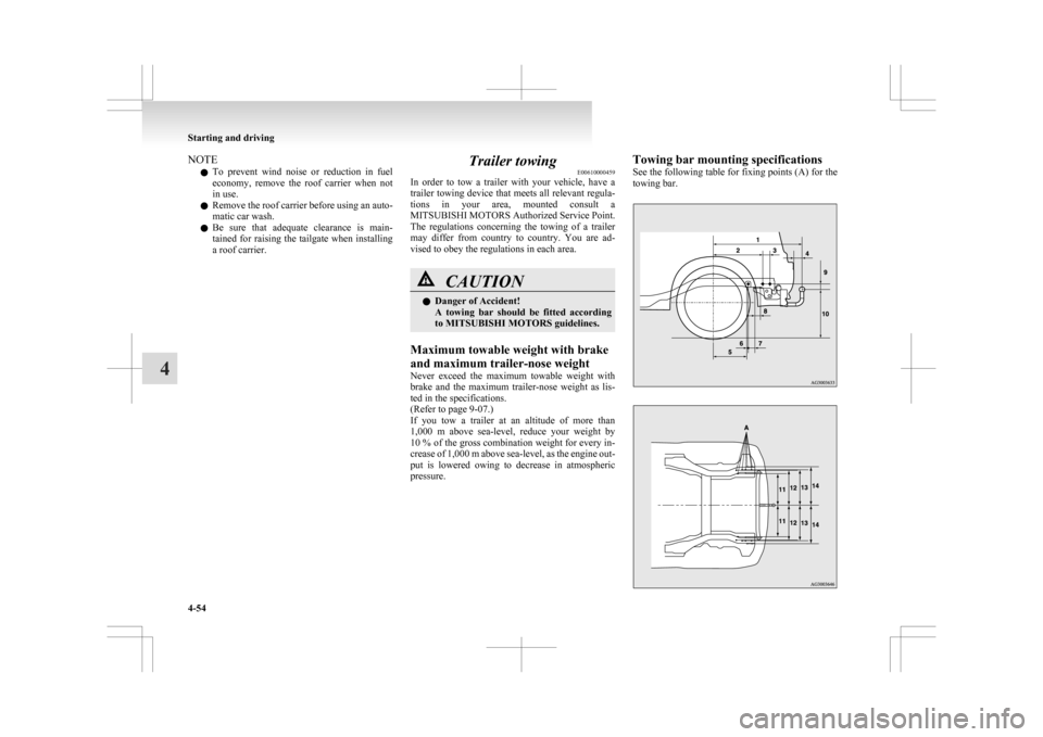
pressure. Towing bar mounting specifications
See
the following table for fixing points (A) for the
towing bar. Starting and driving
4-54
4
Page 207 of 368

1
830.5 mm
2 461 mm
3 68.5 mm
4 75 mm
5 310 mm
6 13.5 mm
7 66.5 mm
8 50 mm
9 52 mm
10 464 mm
(at kerb weight condi- tion)
370 mm to 384 mm (at laden condition)
11 447 mm
12 487 mm
13 495 mm
14 525.5 mmNOTE
l The
values under item 12 can be varied de-
pending on the loading condition of cargo or
luggage.
Operating hints l To prevent the clutch from slipping (Vehicle
with a M/T only), do not rev the engine more
than is required when starting off. l
Be
sure that the driving speed does not ex-
ceed 100 km/h (62 mph) for trailer operation.
It is also recommended that you obey the lo-
cal regulations in case driving speed with a
trailer is limited to less than 100 km/h
(62 mph).
l To prevent shocks from the overrun brake, de-
press the brake pedal lightly at first and then
more strongly.
l To make full use of engine braking, change
to a lower shift point before descending a
slope.
Additional precautions for vehicles equipped with
a CVT
It is recommended the “D” position on slopes or at
low speed.
Use the sports mode in mountainous areas in order
to make better use of engine braking and to assist
the brake system.
However, be sure that the speed does not exceed
the maximum speed limit for the selected shift posi-
tion.
Overheating
This will normally occur as a result of some me-
chanical failure. If your vehicle should overheat,
stop and check for a loose or broken water pump/
alternator drive belt, a blocked radiator air intake
or a low coolant level. If these items are satisfacto-
ry the overheating could be caused by a number of
mechanical causes that would have to be checked
at a competent service centre. CAUTION
l
If the engine overheats, please refer to the
“Engine
overheating” section of “For
emergencies” prior to taking any correc-
tive action.
l On vehicles equipped with CVT, if the warning display is showing, the tempera-
ture of the CVT fluid is high.
Read
the reference page and take the re-
quired measures.
Refer to “When a malfunction occurs in
the CVT” on page 4-27. Starting and driving
4-55 4