2009 MITSUBISHI ASX steering wheel
[x] Cancel search: steering wheelPage 289 of 368
CAUTION
l
If you sense any abnormality while driv-
ing, stop the vehicle and contact a
MITSUBISHI MOTORS Authorized
Service Point or another specialist. Other-
wise the tyre pressure may drop before
the emergency repair procedure is com-
pleted, rendering the vehicle unsafe.
NOTE l Driving
faster than 80 km/h (50 mph) can
make the vehicle vibrate.
18. After driving for 10 minutes or 5 km (3 miles), check the tyre pressure using the
air pressure gauge on the compressor.
(Refer to “Tyre inflation pressures” on page
8-12.)
If the tyre pressure is not sufficient, inflate
the tyre to the specified pressure again and
drive the vehicle carefully without exceeding
a speed of 80 km/h (50 mph). CAUTION
l
If
the tyre pressure is lower than the min-
imum permitted pressure (1.3 bar
{130 kPa}), the tyre cannot successfully
be repaired with the tyre sealant. Do not
drive the vehicle any further. Contact a
MITSUBISHI MOTORS Authorized
Service Point or another specialist.
19. After
driving for 10 minutes or 5 km (3 miles), check the tyre pressure using the
air pressure gauge on the compressor. (Refer to “Tyre
inflation pressures” on page 8-12.)
If the tyre pressure has apparently not drop-
ped, the emergency repair procedure is com-
plete. You must still not exceed a speed of
80 km/h (50 mph). Observe local speed limits.
NOTE l If the tyre pressure has dropped below the
specified level when you check it at the end
of the repair procedure, do not drive the vehi-
cle any further. Contact a MITSUBISHI
MOTORS Authorized Service Point or anoth-
er specialist.
l In cold conditions (when the ambient temper-
ature is 0 °C or lower), the time and driving
distance necessary until completion of the re-
pair can be longer than in warmer conditions,
meaning that the tyre pressure can drop be-
low the specified level even when you have
inflated the tyre a second time and subsequent-
ly driven the vehicle. If this happens, inflate
the tyre to the specified pressure once more,
drive for about 10 minutes or 5 km (3 miles),
then check the tyre pressure again. If the tyre
pressure has again dropped below the speci-
fied level, stop driving the vehicle and con-
tact a MITSUBISHI MOTORS Authorized
Service Point or another specialist.
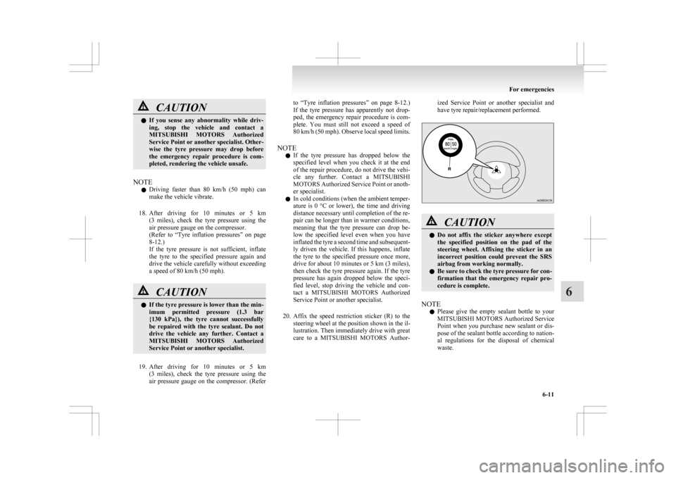
20. Affix the speed restriction sticker (R) to the steering wheel at the position shown in the il-
lustration. Then immediately drive with great
care to a MITSUBISHI MOTORS Author- ized Service Point or another specialist and
have tyre repair/replacement performed.
CAUTION
l
Do
not affix the sticker anywhere except
the specified position on the pad of the
steering wheel. Affixing the sticker in an
incorrect position could prevent the SRS
airbag from working normally.
l Be sure to check the tyre pressure for con-
firmation that the emergency repair pro-
cedure is complete.
NOTE l Please
give the empty sealant bottle to your
MITSUBISHI MOTORS Authorized Service
Point when you purchase new sealant or dis-
pose of the sealant bottle according to nation-
al regulations for the disposal of chemical
waste. For emergencies
6-11 6
Page 291 of 368
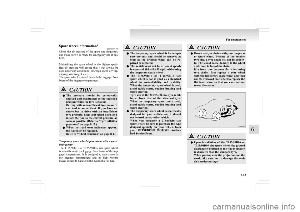
Spare wheel information*
E00803600497
Check
the air pressure of the spare tyre frequently
and make sure it is ready for emergency use at any
time.
Maintaining the spare wheel at the highest speci-
fied air pressure will ensure that it can always be
used under any conditions (city/high-speed driving,
varying load weight, etc.).
The spare wheel is stored beneath the luggage floor
board of the luggage compartment. CAUTION
l
The
pressure should be periodically
checked and maintained at the specified
pressure while the tyre is stowed.
Driving with an insufficient tyre pressure
can lead to an accident. If you have no
choice but to drive with an insufficient
tyre pressure, keep your speed down and
inflate the tyre to the correct pressure as
soon as possible. (Refer to “Tyre inflation
pressures” on page 8-12.)
l When the tread wear indicators appear,
the tyre must be replaced.
Refer to “Wheel condition” on page 8-13.
Temporary spare wheel (spare wheel with a speed
limit label)*
The T155/90D16
or T125/90D16 size spare wheel
is stored beneath the luggage floor board of the lug-
gage compartment. It is designed to save space in
the luggage compartment and its light weight
makes it easy to handle in the event of a flat tyre. CAUTION
l
The
temporary spare wheel is for tempo-
rary use only and should be removed as
soon as the original wheel can be re-
paired or replaced.
l The vehicle must not be driven at speeds
in excess of 80 km/h (50 mph) while using
the temporary spare wheel.
l The T155/90D16 or T125/90D16 size
spare wheel is not as good as a standard
wheel in controllability and stability.
When the temporary spare wheel is used,
avoid quick starts, sudden braking and
sharp steering.
Tyre size of the 215/65R16 size tyre is dif-
ferent from that of the standard tyre.
When the temporary spare tyre is used,
avoid quick starts, sudden braking and
sharp steering.
l The temporary spare wheel is specifically
designed for your vehicle and it should
not be used on any other vehicle.
When you purchase a 215/65R16 size
spare wheel, be sure to purchase the type
designed specially for your vehicle from
your MITSUBISHI MOTORS Author-
ized Service Point. CAUTION
l
Do not use tyre chains with your tempora-
ry spare wheel. Because of the smaller
tyre size, a tyre chain will not fit proper-
ly. This could cause damage to the wheel
and result in loss of the chain.
If a front tyre becomes flat when using
tyre chains, first replace a rear wheel
with the temporary spare wheel and then
use the removed rear wheel to replace the
flat front wheel so that you can continue
to use the chains. CAUTION
l
Upon
installation of the T155/90D16 or
T125/90D16 size spare wheel, the ground
clearance is reduced as the tyre is smaller
in diameter than the standard tyre.
When passing over the projections on the
road, take care not to damage the vehi-
cle’s undercarriage. For emergencies
6-13 6
Page 295 of 368
8. Lower the vehicle slowly by rotating the
wheel nut wrench anticlockwise until the
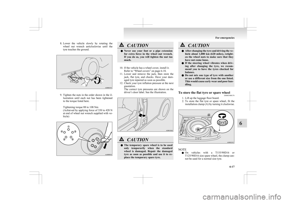
tyre touches the ground. 9. Tighten
the nuts in the order shown in the il-
lustration until each nut has been tightened
to the torque listed here.
Tightening torque 88 to 108 Nm
(Achieved by applying force of 350 to 420 N
at end of wheel nut wrench supplied with ve-
hicle) CAUTION
l
Never
use your foot or a pipe extension
for extra force in the wheel nut wrench.
If you do so, you will tighten the nut too
much.
10. If the vehicle has a wheel cover, install it. Refer to “Wheel covers” on page
6-18.
11. Lower and remove the jack, then store the jack, flat tyre, and chocks. Have your dam-
aged tyre repaired as soon as possible.
12. Check your tyre inflation pressure at the next gasstation.
The correct tyre pressures are shown on the
driver’s door label. See the illustration. CAUTION
l
The
temporary spare wheel is to be used
only temporarily when the standard
wheel is damaged. Repair the damaged
tyre as soon as possible and use it to re-
place the temporary spare tyre. CAUTION
l
After
changing the tyre and driving the ve-
hicle about 1,000 km (620 miles), retight-
en the wheel nuts to make sure that they
have not come loose.
l If the steering wheel vibrates when driv-
ing after changing the tyre, we recom-
mend you to have the tyres checked for
balance.
l Do not mix one type of tyre with another
or use a different size from the one listed.
This would cause early wear and poor han-
dling.
To store the flat tyre or spare wheel E00803400176
1. Lift up the luggage floor board.
2. To
store the flat tyre or spare wheel, fit the
installation clamp (A) by turning it clockwise. NOTE
l On
vehicles with a T155/90D16 or
T125/90D16 size spare wheel, the clamp can-
not be used for a normal size tyre. For emergencies
6-17 6
Page 298 of 368
![MITSUBISHI ASX 2009 1.G Owners Manual CAUTION
l
[For 2WD vehicles equipped with the Ac-
tive Stability Control (ASC)]
If the vehicle is towed with the ignition
switch in the “ON” position or the opera-
tion mode in ON and MITSUBISHI ASX 2009 1.G Owners Manual CAUTION
l
[For 2WD vehicles equipped with the Ac-
tive Stability Control (ASC)]
If the vehicle is towed with the ignition
switch in the “ON” position or the opera-
tion mode in ON and](/manual-img/19/7566/w960_7566-297.png)
CAUTION
l
[For 2WD vehicles equipped with the Ac-
tive Stability Control (ASC)]
If the vehicle is towed with the ignition
switch in the “ON” position or the opera-
tion mode in ON and only the front
wheels or only the rear wheels raised off
the ground (Type B or C), the ASC may
operate, resulting in an accident.
When towing the vehicle with the rear
wheels raised, turn the ignition switch to
the “ACC” position or put the operation
mode in ACC.
When towing the vehicle with the front
wheels raised, keep the ignition switch or
the operation mode as follows.
[Except for vehicles equipped with key-
less operation system]
The ignition switch is in “LOCK” or
“ACC” position.
[Vehicles with keyless operation system]
The operation mode is in OFF or ACC.
Towing with rear wheels off the ground (Type B)
Place
the gearshift lever in the “N” (Neutral) posi-
tion.
Turn the ignition switch to the “ACC” position or
put the operation mode in ACC and secure the steer-
ing wheel in a straight-ahead position with a rope
or tiedown strap. Never place the ignition switch in
the “LOCK” position or put the operation mode in
OFF when towing.
Towing with front wheels off the ground (Type C)
Release the parking brake. Place the gearshift lever in the “N” (Neutral) posi-
tion
(M/T) or the selector lever in the “N” (NEU-
TRAL) position (CVT).
Emergency towing
If towing service is not available in an emergency,
your vehicle may be temporarily towed by a rope
secured to the towing hook.
If your vehicle is to be towed by another vehicle or
if your vehicle tows another vehicle, pay careful at-
tention to the following points:
If your vehicle is to be towed by another vehicle
1. The front towing hook (A) is located asshown in the illustration. Secure the tow rope
to the front towing hook. NOTE
l Do
not use the tie-down hooks (B) for tow-
ing. These hooks are provided only for the
purpose of transporting the vehicle itself.
Using any part other than the designated tow-
ing hook (A) could result in damage to vehi-
cle body. l
Using
a wire rope or metal chain can result
in damage to the vehicle body. It is best to
use a non-metallic rope. If you use a wire
rope or metal chain, wrap it with cloth at any
point where it touches the vehicle body.
l Take care that the tow rope is kept as horizon-
tal as possible. An angled tow rope can dam-
age the vehicle body.
2. Keep the engine running. If the engine is not running, perform the fol-
lowing operation to unlock the steering wheel.
[Except for vehicles with keyless operation
system]
Turn the ignition switch to the “ACC” or
“ON” position (M/T) or “ON” position
(CVT).
[For vehicles with the keyless operation sys-
tem]
Put the operation mode in ACC or ON (M/T)
or ON (CVT).
NOTE l For vehicles equipped with the Auto Stop &
Go (AS&G) system, press the “Auto Stop &
Go (AS&G) OFF” switch to deactivate the
Auto Stop & Go (AS&G) system before stop-
ping the vehicle.
Refer to “To deactivate” on page 4-20. For emergencies
6-20
6
Page 299 of 368
WARNING
l When the engine is not running, the
brake booster and power steering system
do not operate. This means higher brake
depression force and higher steering ef-
fort are required. Therefore, vehicle oper-
ation is more difficult than usual. CAUTION
l
Do
not leave the ignition switch in the
“LOCK” position or the operation mode
in OFF. The steering wheel will lock, caus-
ing loss of control.
3. Place
the gearshift lever in the “N” (Neutral) position (M/T) or the selector lever in the
“N” (NEUTRAL) position (CVT).
4. Turn on the hazard warning lamps if required by law.
(Follow the local driving laws and regula-
tions.) CAUTION
l
The
person in the vehicle being towed
must pay attention to the brake lamps of
the towing vehicle and make sure the
rope never becomes slack.
l Avoid sudden braking, sudden accelera-
tion and sharp turning; such operation
could cause damage to the towing hooks
or the tow rope.
People in the vicinity could be injured as
a result. CAUTION
l
When
towing or being towed down a long
slope, the brakes may overheat reducing
the effectiveness. In this situation, have
your vehicle transported by a tow truck.
l When the vehicle equipped with CVT is
to be towed by another vehicle with the
all wheels on the ground, make sure that
the towing speed and distance given be-
low are never exceeded, causing damage
to the transmission.
Towing speed: 40 km/h (25 mph)
Towing distance: 40 km (25 miles)
For the towing speed and the towing dis-
tance, follow the local driving laws and
regulations.
If your vehicle tows another vehicle 1. Take
out the towing hook, wheel nut wrench
and jack bar.
Refer to “Tools, jack and tyre repair kit” on
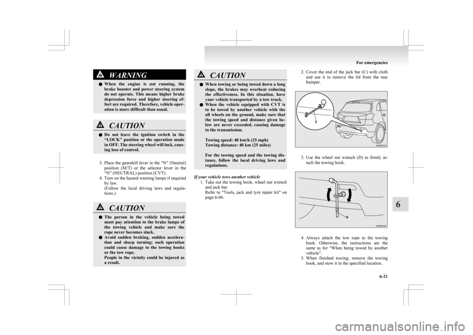
page 6-06. 2. Cover
the end of the jack bar (C) with cloth
and use it to remove the lid from the rear
bumper. 3. Use
the wheel nut wrench (D) to firmly at-
tach the towing hook. 4. Always
attach the tow rope to the towing
hook. Otherwise, the instructions are the
same as for “When being towed by another
vehicle”.
5. When finished towing, remove the towing hook, and stow it in the specified location. For emergencies
6-21 6
Page 300 of 368
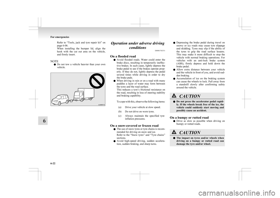
Refer to “Tools,
jack and tyre repair kit” on
page 6-06.
When installing the bumper lid, align the
hook with the cut out area on the vehicle,
and firmly insert.
NOTE l Do not tow a vehicle heavier than your own
vehicle. Operation under adverse driving
conditions E00801702531
On a flooded road l Avoid
flooded roads. Water could enter the
brake discs, resulting in temporarily ineffec-
tive brakes. In such cases, lightly depress the
brake pedal to see if the brakes operate prop-
erly. If they do not, lightly depress the pedal
several times while driving in order to dry
the brake pads.
l When driving in rain or on a road with many
puddles a layer of water may form between
the tyres and the road surface.
This reduces a tyre’s frictional resistance on
the road, resulting in loss of steering stability
and braking capability.
To cope with this, observe the following items:
(a) Drive your vehicle at slow speed.
(b) Do not drive on worn tyres.
(c) Always maintain the specified tyre inflation pressures.
On a snow-covered or frozen road l The
use of snow tyres or tyre chains is recom-
mended for driving on snow and ice.
Refer to the “Snow tyres” and “Tyre chains”
sections.
l Avoid high-speed driving, sudden accelera-
tion, sudden braking, and sharp turns. l
Depressing
the brake pedal during travel on
snowy or icy roads may cause tyre slippage
and skidding. Tyres may slip if the ability of
the tyres to grip the road surface lessens.
This may make it more difficult to stop the
vehicle with normal braking operations. For
vehicles with an anti-lock brake system
(ABS), firmly depress and hold down the
brake pedal.
l Allow extra distance between your vehicle
and the vehicle in front of you, and avoid sud-
den braking.
l Accumulation of ice on the braking system
can cause the wheels to lock. Pull away from
a standstill slowly after confirming safety
around the vehicle. CAUTION
l
Do
not press the accelerator pedal rapid-
ly. If the wheels break free of the ice, the
vehicle could suddenly start moving and
possibly cause an accident.
On a bumpy or rutted road l Drive
as slow as possible when driving on
bumpy or rutted roads. CAUTION
l
The
impact on tyres and/or wheels when
driving on a bumpy or rutted road can
damage the tyre and/or wheel. For emergencies
6-22
6
Page 357 of 368

4
4-wheel drive operation 4-31
AAccessory (Installation) 04
Accessory socket 5-61
Active stability control (ASC)
4-40
Additional equipment 8-17
Air conditioning 5-03 Important operation tips for the air condition-
ing 5-09
Air purifier 5-10
Airbag 2-24
Antenna 5-39
Anti-lock brake system (ABS) 4-38 Display 4-38
Warning lamp 4-38
Ashtray 5-60
Assist grips 5-70
Audio 5-10 Error codes 5-35
External audio input function 5-32
Handling of compact discs 5-38
Steering wheel audio remote control
switches 5-33
Auto Stop & Go (AS&G) system 4-17
Automatic transmission Fluid 9-14
Selector lever operation 4-24
Selector lever position 4-25
Sports mode 4-26
BBattery 8-08
Charge warning lamp 3-42 Discharged battery (Emergency starting) 6-02
Disposal information for used batteries
06
Specification 9-11
Bluetooth® 2.0 interface 5-41
Bonnet 8-03
Bottle holder 5-69
Brake assist system 4-36
Brake Anti-lock brake 4-38
Braking 4-34
Fluid 8-07,9-14
Parking brake 4-06
Bulb capacity 8-23
C Capacities 9-14
Card holder 5-59,5-66
Cargo loads 4-52
Catalytic converter
8-02
Cautions on handling of 4-wheel drive vehi-
cles 4-33
Central door locks 1-22
Charge warning lamp 3-42
Chassis number 9-02
Check engine warning lamp 3-41
Child restraint 2-15
Child-protection rear doors 1-25
Cigarette lighter 5-60
Cleaning Exterior of your vehicle 7-03
Interior of your vehicle 7-02
Clock 5-39
Clutch Fluid 8-07
Coat hook 5-70
Combination headlamps and dipper switch 3-44
Coolant (engine) 8-06,9-14
Cruise control 4-43 Cup holder 5-68
D Daytime running lamps
Bulb capacity
8-24
Replacement 8-30
Demister (rear window) 3-57
Diesel particulate filter (DPF) 4-15
Dimensions 9-04
Dipper (High/Low beam change) 3-47
Doors Central door locks 1-22
Child-protection 1-25
Dead Lock System 1-23
Lock and unlock 1-21
Driving, alcohol and drugs 4-02
E Economical driving 4-02
Electric power steering system (EPS)
4-40
Electric window control 1-34
Electrical system 9-11
Electronic immobilizer (Anti-theft starting sys-
tem) 1-03
Electronically controlled 4WD system 4-29
Emergency starting 6-02
Emergency stop signal system 4-37
Engine specifications 9-10
Engine switch 1-11
Engine Coolant 8-06,9-14
Number 9-02
Oil 8-04
Oil and filter 9-14
Overheating 6-04
Specifications 9-10 Alphabetical index
1
Page 359 of 368

Bulb capacity 8-24
Mirror Inside rear-view mirror 4-08
Outside rear-view mirrors 4-09
Modification/alterations
to the electrical or fuel sys-
tems 05
Multi-information display 3-03
OOil
Engine oil 8-04
Manual transmission oil 9-14
Rear differential oil
9-14
Transfer oil 9-14
Operation mode 1-12
Operation under adverse driving conditions 6-22
Outside rear-view mirrors 4-09
Overheating 6-04
PParking 4-07
Parking brake 4-06
Parking brake break-in 8-15
Position lamps Bulb capacity
8-24
Replacement 8-27
Power steering Fluid 9-14
Precautions to observe when using wipers and wash-
ers 3-56
Pregnant women restraint 2-14
Puncture Tyre changing 6-12
Tyre repair kit 6-07 RRear combination lamps
Bulb capacity
8-24
Replacement 8-31
Rear differential oil 9-14
Rear fog lamp Bulb capacity 8-24
Replacement 8-31
Switch 3-51
Rear room lamp Bulb capacity 8-24
Rear shelf panel 5-69
Rear turn-signal lamps Bulb capacity 8-24
Replacement 8-31
Rear window demister switch 3-57
Rear-view camera 4-50
Rear-view mirror Inside 4-08
Outside 4-09
Refill capacities 9-14
Replacement of lamp bulbs 8-23
Reversing lamps Bulb capacity 8-24
Replacement 8-31
Reversing sensor system 4-47
Roof carrier precaution 4-53
Room lamp (front) 5-62
Room lamp (rear) 5-63
Running-in recommendations 4-04
S Safe driving techniques 4-03
Seat belt 2-10
Adjustable seat belt anchor
2-12
Child restraint 2-15 Force limiter 2-15
Inspection 2-24
Pregnant women restraint
2-14
Pretensioner 2-14
Seat Adjustment 2-03
Front seat 2-03
Head restraints 2-07
Heated seats 2-06
Making a luggage compartment 2-08
Rear seat 2-06
Security alarm system 1-28
Service precaution 8-02
Side turn-signal lamp Bulb capacity 8-24
Side turn-signal lamps Replacement 8-29
Snow tyres 8-14
Spare wheel 6-13
Spark plug 9-11
Specifications 9-02
Starting 4-13
Starting and stopping the engine 1-15
Steering Power steering fluid 9-14
Steering wheel height and reach adjust-
ment 4-08
Steering wheel lock 1-14,4-12
Stop and tail lamps Replacement 8-31
Stop lamps Bulb capacity 8-23
Storage spaces 5-65
Sun visors 5-59
Sunshade 1-36
Sunshade illumination 5-64
Supplemental restraint system 2-24 Servicing 2-34 Alphabetical index
3