2009 MITSUBISHI ASX rear view mirror
[x] Cancel search: rear view mirrorPage 41 of 368

l
It is possible to modify functions as follows:
For
further information, please contact your
MITSUBISHI MOTORS Authorized Service
Point.
On vehicles equipped with MITSUBISHI
Multi-Communication System (MMCS),
screen operations can be used to make the ad-
justment. Refer to the separate owner’s man-
ual for details. • The time from pressing the UNLOCKswitch (2) to the moment of automatic
locking can be changed.
• The confirmation function (flashing of the turn-signal lamps) can be set to oper-
ate only when the doors and backdoor are
locked or only when the doors and back-
door are unlocked.
• The confirmation function (this indicates locking or unlocking of the doors and tail-
gate with the flash of the turn-signal
lamps) can be deactivated.
• The number of times the turn-signal lamps are flashed by the confirmation
function can be changed.
Operation of the Dead Lock System
In a vehicle that has a Dead Lock System, it is pos-
sible to set the Dead Lock System using the remote
controller.
(Refer to “Dead Lock System” on page 1-23.)
Operation of the outside rear-view mirrors (Vehi-
cles equipped with mirror retractor switch) E00311200110
To fold
Within
30 seconds of locking the doors and tailgate
using the LOCK switch (1), press the LOCK
switch twice rapidly to fold the outside rear-view
mirrors. To extend
Within
30 seconds of unlocking the doors and tail-
gate using the UNLOCK switch (2), press the UN-
LOCK switch twice rapidly to return the outside
rear-view mirrors to their extended positions.
The outside rear-view mirrors are not initially set
to
work as described above. If you want them to
work as described above, you need to set them so
that they do not retract/extend when the doors and
tailgate are locked/unlocked using the keyless en-
try system or keyless operation system.
Refer to “Starting and driving: Outside rear-view
mirrors” on page 4-09.
For details, please consult a MITSUBISHI
MOTORS Authorized Service Point.
In a vehicle equipped with the MITSUBISHI Mul-
ti-Communication System (MMCS), it is possible
to change the setting by means of screen operations.
Refer to the separate owner’s manual for details. NOTE
l For
vehicles equipped with the mirror retrac-
tor switch, the outside rear-view mirrors auto-
matically retract or extend when all the doors
and tailgate are locked or unlocked using the
remote control switches of the keyless entry
system.
Refer to “Starting and driving: Outside rear-
view mirrors” on page 4-09.
l The keyless entry system does not operate
when one of the doors or the tailgate is open. l
The
remote control switch will operate with-
in approximately 4 m from the vehicle. How-
ever, the operating range of the remote con-
trol switch may change if the vehicle is loca-
ted near a power station, or radio/TV broad-
casting station.
l If either of the following problems occurs,
the battery may be exhausted.
• The remote control switch is operated atthe correct distance from the vehicle, but
the doors and tailgate are not locked/un-
locked in response.
• The indication lamp (3) is dim or does not come on.
For further information, please contact
your MITSUBISHI MOTORS Author-
ized Service Point.
If you replace the battery yourself, refer
to “Procedure for replacing the remote
control switch battery” on page 1-20.
l If your remote control switch is lost or dam-
aged, please contact your MITSUBISHI
MOTORS Authorized Service Point for a re-
placement remote control switch.
l If you wish to add a remote control switch,
please contact your MITSUBISHI MOTORS
Authorized Service Point. A maximum of 4
remote control switches are available for
your vehicle.
Setting of door and tailgate unlock function (Ex-
cept for vehicles equipped with a Dead Lock Sys-
tem) E00310400199
The door and tailgate unlock function can be set to
the following two conditions. Locking and unlocking
1-19 1
Page 151 of 368

Rear window demister switch
E00507901186
The
rear window demister switch can be operated
when the engine is running.
Push the switch to turn on the rear window demis-
ter. It will be turned off automatically in about 20
minutes. To turn off the demister within about 20
minutes, push the switch again.
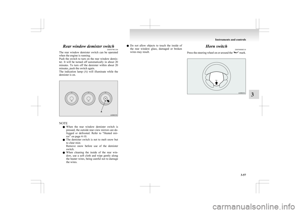
The indication lamp (A) will illuminate while the
demister is on. NOTE
l When
the rear window demister switch is
pressed, the outside rear-view mirrors are de-
fogged or defrosted. Refer to “Heated mir-
ror” on page 4-10.
l The demister switch is not to melt snow but
to clear mist.
Remove snow before use of the demister
switch.
l When cleaning the inside of the rear win-
dow, use a soft cloth and wipe gently along
the heater wires, being careful not to damage
the wires. l
Do
not allow objects to touch the inside of
the rear window glass, damaged or broken
wires may result. Horn switch
E00508000318
Press
the steering wheel on or around the “ ”
mark.Instruments and controls
3-57 3
Page 153 of 368

Economical driving.......................................................................4-02
Driving, alcohol and drugs
........................................................... 4-02
Safe driving techniques ................................................................ 4-03
Running-in recommendations
.......................................................4-04
Parking brake................................................................................ 4-06
Parking.......................................................................................... 4-07
Steering wheel height and reach adjustment ................................4-08
Inside rear-view mirror ................................................................. 4-08
Outside rear-view mirrors ............................................................. 4-09
Ignition switch .............................................................................. 4-11
Steering wheel lock ...................................................................... 4-12
Starting..........................................................................................4-13
Diesel particulate filter (DPF)* .................................................... 4-15
Turbocharger operation* .............................................................. 4-16
Auto Stop & Go (AS&G) system*............................................... 4-17
Manual transmission* ................................................................... 4-21
Automatic transmission INVECS-III Sports Mode 6CVT (Intelligent & Innovative Vehicle Electronic
Control System III)*................................................................. 4-24
Electronically controlled 4WD system* .......................................4-29
4-wheel drive operation ................................................................ 4-31
Inspection and maintenance following rough road oper- ation.......................................................................................... 4-33
Cautions on handling of 4-wheel drive vehicles ..........................4-33
Braking......................................................................................... 4-34
Hill start assist* ............................................................................ 4-35
Brake assist system....................................................................... 4-36
Emergency stop signal system ...................................................... 4-37
Anti-lock brake system (ABS) ..................................................... 4-38
Electric power steering system (EPS) ..........................................4-40 Active stability control (ASC)*
.................................................... 4-40
Cruise control* ............................................................................. 4-43
Reversing sensor system*............................................................. 4-47
Rear-view camera* ....................................................................... 4-50
Cargo loads................................................................................... 4-52
Trailer towing ............................................................................... 4-54Starting and driving
4
Page 160 of 368

Steering wheel height and reach
adjustment E00600700512
1. Release
the lever while holding the steering
wheel up.
2. Adjust the steering wheel to the desired posi- tion.
3. Securely lock the steering wheel by pulling the lever fully upward. A- Locked
B-
Release WARNING
l Do
not attempt to adjust the steering
wheel while you are driving the vehicle. Inside rear-view mirror
E00600800366
Adjust
the rear-view mirror only after making any
seat adjustments so you have a clear view to the
rear of the vehicle. WARNING
l Do
not attempt to adjust the rear-view
mirror while driving. This can be danger-
ous.
Always adjust the mirror before driving.
Adjust the rear-view mirror to maximize the view
through the rear window.
To adjust the vertical mirror position
It
is possible to move the mirror up and down to ad-
just its position. To reduce the glare
The
lever (A) at the bottom of the mirror can be
used to adjust the mirror to reduce the glare from
the headlamps of vehicles behind you during night
driving. 1- Normal
2-
Anti-glare Starting and driving
4-08
4
Page 161 of 368

Outside rear-view mirrors
E00600900628
To adjust the mirror position E00601000642
The outside rear-view mirrors can be operated
when
the ignition switch or the operation mode is
in ON or ACC. WARNING
l Do
not attempt to adjust the rear-view
mirrors while driving. This can be danger-
ous.
Always adjust the mirrors before driving.
l Your vehicle is equipped with convex
type mirrors.
Please take into consideration, that ob-
jects you see in the mirror will look small-
er and farther away compared to a nor-
mal flat mirror.
Do not use this mirror to estimate dis-
tance of following vehicles when changing
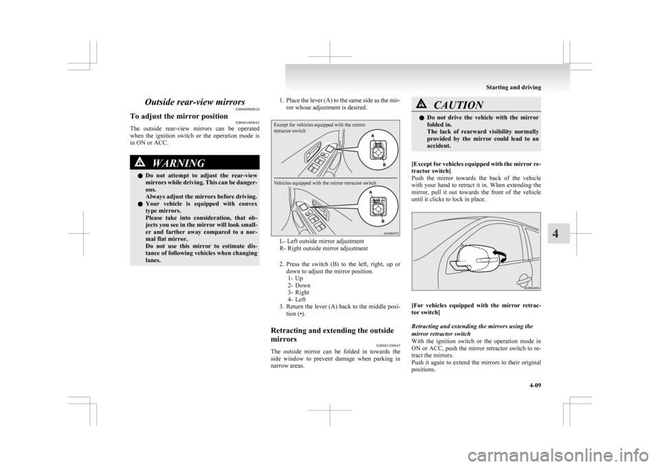
lanes. 1. Place
the lever (A) to the same side as the mir-
ror whose adjustment is desired.
Except for vehicles equipped with the mirror
retractor switch
Vehicles equipped with the mirror retractor switch L- Left outside mirror adjustment
R- Right outside mirror adjustment
2. Press
the switch (B) to the left, right, up or
down to adjust the mirror position. 1- Up
2- Down
3- Right
4- Left
3. Return the lever (A) back to the middle posi- tion (•).
Retracting and extending the outside
mirrors E00601100643
The outside mirror can be folded in towards the
side
window to prevent damage when parking in
narrow areas. CAUTION
l
Do
not drive the vehicle with the mirror
folded in.
The lack of rearward visibility normally
provided by the mirror could lead to an
accident.
[Except
for vehicles equipped with the mirror re-
tractor switch]
Push the mirror towards the back of the vehicle
with your hand to retract it in. When extending the
mirror, pull it out towards the front of the vehicle
until it clicks to lock in place. [For
vehicles equipped with the mirror retrac-
tor switch]
Retracting and extending the mirrors using the
mirror retractor switch
With the ignition switch or the operation mode in
ON or ACC, push the mirror retractor switch to re-
tract the mirrors.
Push it again to extend the mirrors to their original
positions. Starting and driving
4-09 4
Page 162 of 368

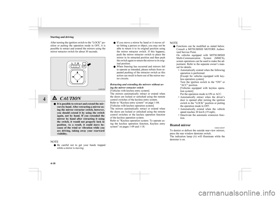
After turning the ignition switch to the “LOCK” po-
sition
or putting the operation mode in OFF, it is
possible to retract and extend the mirrors using the
mirror retractor switch for about 30 seconds. CAUTION
l
It
is possible to retract and extend the mir-
rors by hand. After retracting a mirror us-
ing the mirror retractor switch, however,
you should extend it by using the switch
again, not by hand. If you extended the
mirror by hand after retracting it using
the switch, it would not properly lock in
position. As a result, it could move be-
cause of the wind or vibration while you
are driving, taking away your rearward
visibility.
NOTE l Be
careful not to get your hands trapped
while a mirror is moving. l
If
you move a mirror by hand or it moves af-
ter hitting a person or object, you may not be
able to return it to its original position using
the mirror retractor switch. If this happens,
push the mirror retractor switch to place the
mirror in its retracted position and then push
the switch again to return the mirror to its orig-
inal position.
l When freezing has occurred and mirrors fail
to operate as intended, please refrain from re-
peated pushing of the retractor switch as this
action can result in burn-out of the mirror mo-
tor circuits.
Retracting and extending the mirrors without us-
ing the mirror retractor switch
[Vehicles with keyless entry system]
The mirrors automatically retract or extend when
the doors are locked or unlocked using the remote
control switches of the keyless entry system.
Refer to “Keyless entry system” on page 1-04.
[Vehicles with keyless operation system]
The mirrors automatically retract or extend when
the doors are locked or unlocked using the remote
control switches or the keyless operation function
of the keyless operation system.
Refer to “Keyless operation system: To operate us-
ing the keyless operation function, Keyless entry
system” on pages 1-09 and 1-18. NOTE
l Functions
can be modified as stated below.
Consult a MITSUBISHI MOTORS Author-
ized Service Point.
On vehicles equipped with MITSUBISHI
Multi-Communication System (MMCS),
screen operations can be used to make the ad-
justment. Refer to the separate owner’s man-
ual for details. • Automatically extend when the followingoperation is performed.
[Except for vehicles equipped with key-
less operation system]
Turn the ignition switch to the “ON” or
“ACC” position.
[Vehicles equipped with keyless opera-
tion system]
Put the operation mode in ON or ACC.
• Automatically retract when the driver’s door is opened after turning the ignition
switch to the “LOCK” position or putting
the operation mode in OFF.
• Automatically extend when the vehicle speed reaches 30 km/h (19 mph).
• Deactivate the automatic extension func- tion.
Heated mirror E00601200497
To demist or defrost the outside rear-view mirrors,
press the rear window demister switch.
The
indication lamp (A) will illuminate while the
demister is on. Starting and driving
4-10
4
Page 327 of 368

No. Symbol Electrical system Capaci-
ties
7 Radio 15 A
8 Control unit relay 7.5 A
9 Interior lamps
(Room lamps) 15 A
10 Hazard warning
flasher 15 A
11 Rear window wiper 15 A
12 Instruments 7.5 A
13 Cigarette lighter/
Accessory socket 15 A
14 Ignition switch 10 A
15 Sunroof 20 A
16 Outside rear-view
mirrors 10 A
17 4-wheel drive sys-
tem 10 A
18 Reversing lamps
(Backup lamps) 7.5 A
19 Accessory socket 15 A
20 Electric window
control 30 A*
21 Rear window de-
mister 30 A*
22 Heated door mirror 7.5 A
23 AC power supply 15 A No. Symbol Electrical system Capaci-
ties
24 Power seats 25 (20) A
25 Heated seat 30 A
*: Fusible link
l Some
fuses may not be installed on your ve-
hicle, depending on the vehicle model or spec-
ifications.
l The table above shows the main equipment
corresponding to each fuse.
Engine compartment fuse location table
Engine compartment fuse location
Behind of the fuse block cover No. Symbol Electrical system Capaci-
ties
1 Front fog lamps 15 A
2 Engine 7.5 A
3 Automatic trans-
mission 20 A
4 Horn 10 A
5 Alternator 7.5 A
6 Headlamp washer 20 A
7 Air conditioning 10 A
8 ETV/Oil cooler fan
(Twin Clutch SST) 15 A
9 Security horn 20 A
10 Wiper de-icer 15 A
11 — ——
12 Electric tailgate 30 A
13 Daytime running
lamps 10 A
14 Headlamp high-
beam (left) 10 A
15 Headlamp high-
beam (right) 10 A
16 Head-
lamp low
beam (left) Dis-
charge 20 A Maintenance
8-21 8
Page 330 of 368

Outside
E01003302527Front1- Front turn-signal lamps: 21 W (WY21W)
2-
Headlamps, high-beam: 60 W (HB3)
3- Type 1 Front fog lamps: 35 W (H8)
Daytime running lamps: 13 W (P13W)
Type 2 Daytime running lamps: 13 W (P13W)
Type 3 Front fog lamps: 55 W (H11)
4- Headlamps, low beam Halogen: 55 W (H11)
High intensity discharge *2
: 35 W
5- Position lamps: 5 W (W5W)
6- Side turn-signal lamps (on fender) *1
,*2
: 5 W
7- Side turn-signal lamps (on outside rear-view
mirror) *1
*1 : if so equipped
*2 : Have the lamps bulbs replaced at a
MITSUBISHI MOTORS
Authorized
Service Point.
Codes in parentheses indicate bulb types. WARNING
l Always
consult a specialist when repair-
ing or replacing the bulbs of high intensi-
ty discharge headlamps.
This is because the power circuit, bulbs
and electrodes generate a high voltage
that could cause an electric shock.
NOTE l An
LED, not a bulb, is used in the side turn-
signal lamp (on outside rear-view mirror).
Contact a MITSUBISHI MOTORS Author-
ized Service Point when there is a need for re-
pair or replacement.
l For the side turn-signal lamp (on fender), it
is not possible to repair or replace just the bulb.
Contact a MITSUBISHI MOTORS Author-
ized Service Point when there is a need for re-
pair or replacement.
Rear 8- High-mounted stop lamp
9-
Licence plate lamps: 5 W (W5W)
10- Rear fog lamp: 21 W (W21W)
11- Reversing lamps: 16 W (W16W) 12- Rear turn-signal lamps: 21 W (W21W)
13-
Stop and tail lamps
Codes in parentheses indicate bulb types.
NOTE l An LED, not a bulb, is used in the stop lamp/
tail lamp and high-mounted stop lamp. Con-
tact a MITSUBISHI MOTORS Authorized
Service Point when there is a need for repair
or replacement.
Inside E01003401749 1- Room lamp (rear)*: 8 W
2-
Vanity mirror lamps*: 3 W
3- Room lamp (front) & map lamps: 8 W
4- Luggage room lamp: 5 W
5- Glove box lamp: 1.4 W
*: if so equipped Maintenance
8-24
8