2009 MINI COOPER CONVERTIBLE bulb
[x] Cancel search: bulbPage 49 of 172

REFERENCEAT A GLANCE CONTROLS DRIVING TIPS MOBILITY
47
If you do not shift gears with the shift paddles or
accelerate for a certain amount of time, the
transmission automatically returns to D, auto-
matic drive.
>Pull one of the shift paddles.
Transmission shifts up.
>Push one of the shift paddles.
Transmission shifts down.
M1 to M6 is displayed in the gear indicator.
Manually unlock the selector lever lock
If the power supply is interrupted, e.g., if
the battery is dead or disconnected, or
due to an electrical malfunction, the selector
lever lock must be unlocked manually, other-
wise the front wheels are locked-up and the
vehicle cannot be towed.<
Only unlock the selector lever lock manually
when the vehicle is to be towed. Do not forget to
firmly apply the parking brake prior to the tow,
otherwise the vehicle may roll away.
1.Unclip the sleeve of the selector lever.
2.Pull the sleeve up over the selector lever un-
til the sleeve is inside out. Disconnect the ca-
ble connector if necessary.3.Take the hub cover remover1 out of the on-
board tool kit and insert it in the loop on the
front passenger side.
4.Pull the loop up.
5.Move the selector lever into the desired po-
sition by pressing the button on the front of
the selector lever.
Turn signals/
headlamp flasher
1Turn signal indicator
2Headlamp flasher
Using turn signals
Press the lever beyond the resistance point.
To turn off manually, press the lever to the resis-
tance point.
Unusually rapid flashing of the indicator
lamp indicates that an indicator bulb has
failed.<
Indicating a turn briefly
Press the lever as far as the resistance point for
as long as you wish to indicate a turn.
Triple turn signal activation
Press the lever as far as the resistance point.
You can set whether the turn signal is to flash
once or three times.
Page 125 of 172

REFERENCEAT A GLANCE CONTROLS DRIVING TIPS MOBILITY
123
Replacing components
Onboard tool kit
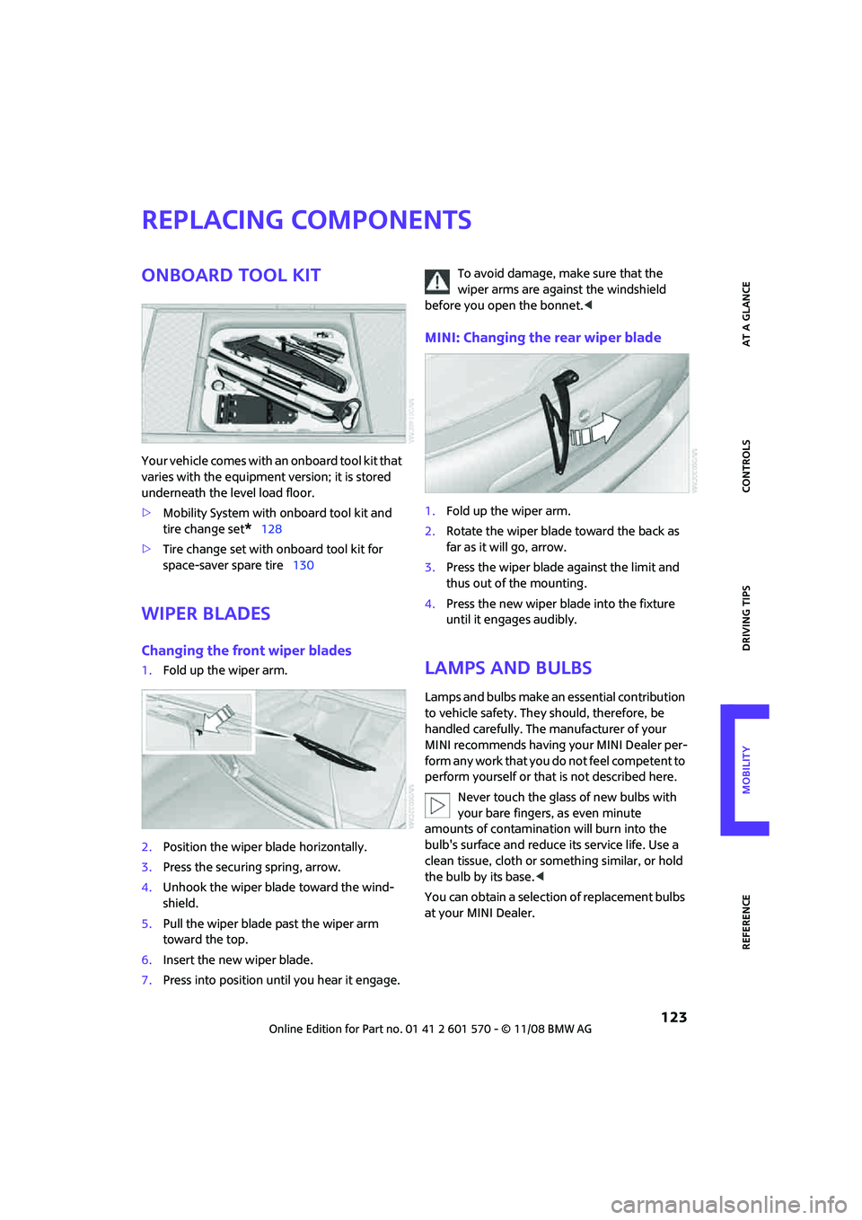
Your vehicle comes with an onboard tool kit that
varies with the equipment version; it is stored
underneath the level load floor.
>Mobility System with onboard tool kit and
tire change set
*128
>Tire change set with onboard tool kit for
space-saver spare tire130
Wiper blades
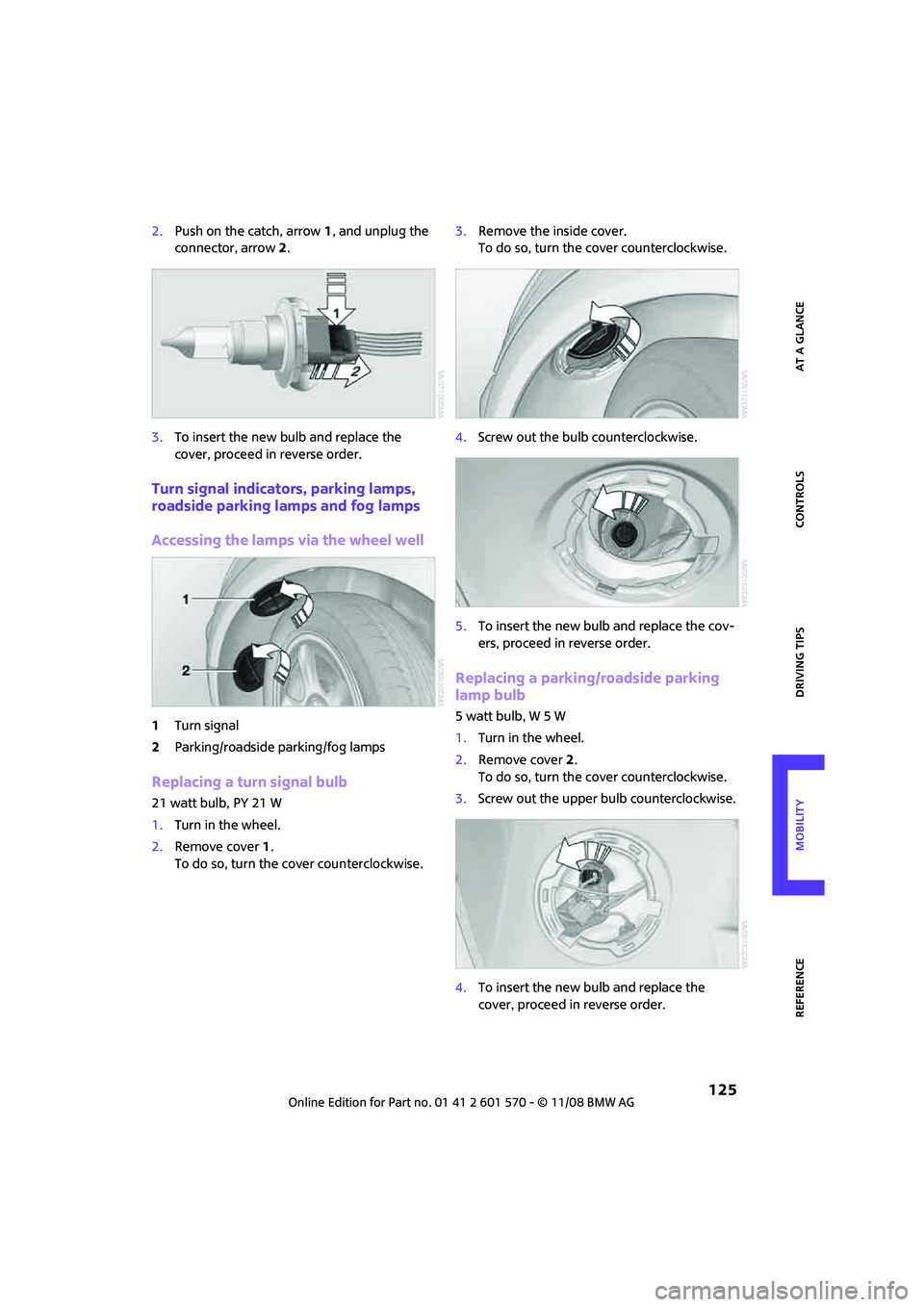
Changing the front wiper blades
1.Fold up the wiper arm.
2.Position the wiper blade horizontally.
3.Press the securing spring, arrow.
4.Unhook the wiper blade toward the wind-
shield.
5.Pull the wiper blade past the wiper arm
toward the top.
6.Insert the new wiper blade.
7.Press into position until you hear it engage.To avoid damage, make sure that the
wiper arms are against the windshield
before you open the bonnet.<
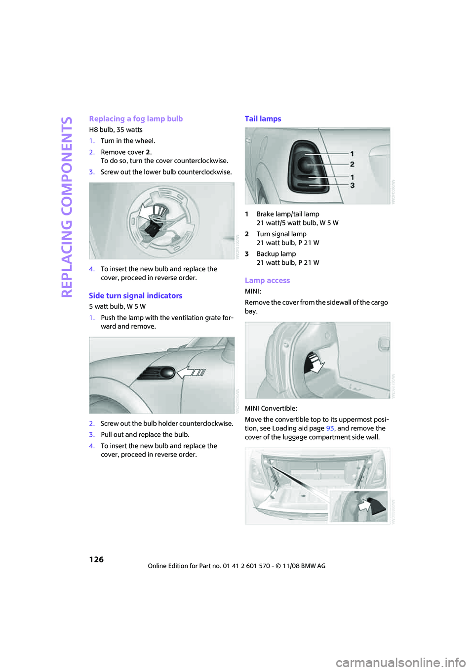
MINI: Changing the rear wiper blade
1.Fold up the wiper arm.
2.Rotate the wiper blade toward the back as
far as it will go, arrow.
3.Press the wiper blade against the limit and
thus out of the mounting.
4.Press the new wiper blade into the fixture
until it engages audibly.
Lamps and bulbs
Lamps and bulbs make an essential contribution
to vehicle safety. They should, therefore, be
handled carefully. The manufacturer of your
MINI recommends having your MINI Dealer per-
form any work that you do not feel competent to
perform yourself or that is not described here.
Never touch the glass of new bulbs with
your bare fingers, as even minute
amounts of contamination will burn into the
bulb's surface and reduce its service life. Use a
clean tissue, cloth or something similar, or hold
the bulb by its base.<
You can obtain a selection of replacement bulbs
at your MINI Dealer.
Page 126 of 172

Replacing components
124
When working on electrical systems,
always begin by switching off the con-
sumer in question, otherwise short circuits could
result. To avoid possible injury or equipment
damage when replacing bulbs, observe any
instructions provided by the bulb manufac-
turer.<
Caring for headlamps, refer to page120.
For any bulb replacement not described
below, contact a MINI Dealer or a work-
shop that has specially trained personnel work-
ing in accordance with the specifications of the
MINI manufacturer.<
For checking and adjusting headlamp aim,
please contact your MINI Dealer.<
Light-emitting diodes LEDs
Light-emitting diodes installed behind translu-
cent lenses serve as the light sources for many of
the controls and displays in your vehicle. These
light-emitting diodes are related to conven-
tional laser diodes, and legislation defines them
as Class 1 light-emitting diodes.
Do not remove the covers or expose the
eyes directly to the unfiltered light source
for several hours, otherwise this could cause irri-
tation to the retina.<
Bi-Xenon lamps*
The service life of these bulbs is very long and
the probability of failure very low, provided that
they are not switched on and off an excessive
number of times. If a xenon lamp fails neverthe-
less, switch on the fog lamps and continue the
journey with great care, provided that local leg-
islation does not prohibit this.
Have any work on the xenon lamp system,
including bulb replacement, carried out
only by a MINI Dealer or a workshop that has
specially trained personnel working in accor-
dance with the specifications of the MINI manu-
facturer. Due to high voltage, there is a risk of
fatal injury if work on the xenon lamps is carried
out improperly.<
Halogen low beams and high beams
H13 bulb, 60/55 watts
The H13 bulb is pressurized. Therefore,
wear safety glasses and protective gloves.
Otherwise there is a risk of injury if the bulb is
damaged.<
Be careful when installing the cover, oth-
erwise leaks could occur and cause dam-
age to the headlamp system.<
Accessing the lamp from the engine
compartment
The low-beam/high-beam bulb can be changed
from the engine compartment.
Removing the cover:
1.Press the tab.
2.Flip open the cover and take it out of the
holder.
Follow the same steps in reverse order to reat-
tach the cover.
Be careful when installing the cover, oth-
erwise leaks could occur and cause dam-
age to the headlamp system.<
Replacing the bulb
1.Turn the lamp counterclockwise, arrow1,
and remove it, arrow2.
Page 127 of 172

REFERENCEAT A GLANCE CONTROLS DRIVING TIPS MOBILITY
125
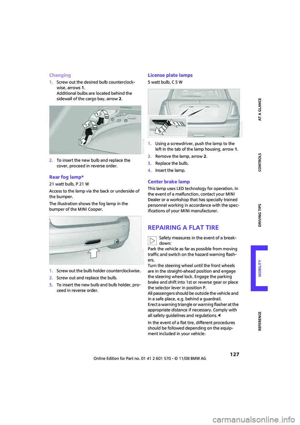
2.Push on the catch, arrow 1, and unplug the
connector, arrow2.
3.To insert the new bulb and replace the
cover, proceed in reverse order.
Turn signal indicators, parking lamps,
roadside parking lamps and fog lamps
Accessing the lamps via the wheel well
1Turn signal
2Parking/roadside parking/fog lamps
Replacing a turn signal bulb
21 watt bulb, PY 21 W
1.Turn in the wheel.
2.Remove cover 1.
To do so, turn the cover counterclockwise.3.Remove the inside cover.
To do so, turn the cover counterclockwise.
4.Screw out the bulb counterclockwise.
5.To insert the new bulb and replace the cov-
ers, proceed in reverse order.
Replacing a parking/roadside parking
lamp bulb
5 watt bulb, W 5 W
1.Turn in the wheel.
2.Remove cover 2.
To do so, turn the cover counterclockwise.
3.Screw out the upper bulb counterclockwise.
4.To insert the new bulb and replace the
cover, proceed in reverse order.
Page 128 of 172

Replacing components
126
Replacing a fog lamp bulb
H8 bulb, 35 watts
1.Turn in the wheel.
2.Remove cover 2.
To do so, turn the cover counterclockwise.
3.Screw out the lower bulb counterclockwise.
4.To insert the new bulb and replace the
cover, proceed in reverse order.
Side turn signal indicators
5 watt bulb, W 5 W
1.Push the lamp with the ventilation grate for-
ward and remove.
2.Screw out the bulb holder counterclockwise.
3.Pull out and replace the bulb.
4.To insert the new bulb and replace the
cover, proceed in reverse order.
Tail lamps
1Brake lamp/tail lamp
21 watt/5 watt bulb, W 5 W
2Turn signal lamp
21 watt bulb, P 21 W
3Backup lamp
21 watt bulb, P 21 W
Lamp access
MINI:
Remove the cover from the sidewall of the cargo
bay.
MINI Convertible:
Move the convertible top to its uppermost posi-
tion, see Loading aid page93, and remove the
cover of the luggage compartment side wall.
Page 129 of 172

REFERENCEAT A GLANCE CONTROLS DRIVING TIPS MOBILITY
127
Changing
1.Screw out the desired bulb counterclock-
wise, arrows1.
Additional bulbs are located behind the
sidewall of the cargo bay, arrow 2.
2.To insert the new bulb and replace the
cover, proceed in reverse order.
Rear fog lamp*
21 watt bulb, P 21 W
Access to the lamp via the back or underside of
the bumper.
The illustration shows the fog lamp in the
bumper of the MINI Cooper.
1.Screw out the bulb holder counterclockwise.
2.Screw out and replace the bulb.
3.To insert the new bulb and bulb holder, pro-
ceed in reverse order.
License plate lamps
5 watt bulb, C 5 W
1.Using a screwdriver, push the lamp to the
left in the tab of the lamp housing, arrow1.
2.Remove the lamp, arrow 2.
3.Replace the bulb.
4.Insert the lamp.
Center brake lamp
This lamp uses LED technology for operation. In
the event of a malfunction, contact your MINI
Dealer or a workshop that has specially trained
personnel working in accordance with the spec-
ifications of your MINI manufacturer.
Repairing a flat tire
Safety measures in the event of a break-
down:
Park the vehicle as far as possible from moving
traffic and switch on the hazard warning flash-
ers.
Turn the steering wheel until the front wheels
are in the straight-ahead position and engage
the steering wheel lock. Engage the parking
brake and shift into 1st or reverse gear or place
the selector lever in position P.
All passengers should be outside the vehicle and
in a safe place, e.g. behind a guardrail.
Erect a warning triangle or warning flasher at the
appropriate distance if necessary. Comply with
all safety guidelines and regulations.<
In the event of a flat tire, different procedures
should be followed depending on the equip-
ment included in your vehicle:
Page 150 of 172

Indicator and warning lamps
148
Selector lever position P not engaged.
Ignition cannot be switched offEngage selector lever position P when
you wish to switch off the ignition,
page43.
Cruise control system failed Have the system checked.
Park Distance Control failed Have the system checked.
Bulb of exterior lighting system failedHave the exterior lighting checked as
soon as possible.
Low-beam headlamp or fog lamp
failedHave the lamps checked as soon as
possible.
High-beam headlamp failed Have the high-beam headlamps
checked.
Rear fog lamp failed Have the rear fog lamp checked.
Headlamp beam throw adjustment
system failedHave the headlamp beam throw
adjustment system checked.
Coolant level too low Add coolant immediately, page115.
Engine oil pressure too low Stop immediately and switch off the
engine. You cannot continue your
journey. Contact your MINI Dealer.
Lights up in red:
Service appointment overdue Arrange a service appointment.
Check service requirements, page57.
Lights up in yellow:
Service due Arrange a service appointment.
Check service requirements, page57.
12Cause What to do
Page 160 of 172

From A to Z
158
From A to Z
INDEX
A
Accessories, refer to Your
individual vehicle4
Activated-charcoal filter for
automatic climate control82
Additives
– coolant115
– engine oil115
Adjusting temperature inside
the car, refer to Air
conditioner79
Adjusting temperature inside
the car, refer to Automatic
climate control80
Air conditioner78
Air conditioning mode
– air conditioner79
– automatic climate control80
– ventilation82
Air distribution
– automatic81
– individual80
– manual80
Air flow rate79,81
– air conditioning system79
– automatic climate control81
– heating, ventilation79
Air outlets, refer to Air vents78
Air pressure, checking, refer to
Tire inflation pressure102
Air recirculation, refer to
Recirculated-air
mode79,81
Air supply
– air conditioner79
– automatic climate control80
– ventilation82
Air vents78
Airbags70
– sitting safely34
– warning lamp72
Airing, refer to Ventilation82AKI, refer to Fuel
specifications101
Alarm system24
All-season tires, refer to Winter
tires112
Always Open Timer54
Ambient air, refer to
Recirculated-air
mode79,81
Ambient lighting77
Antenna, care119
Antifreeze
– coolant115
– washer fluid50
Antilock Brake System ABS63
Anti-theft alarm system, refer
to Alarm system
24
Anti-theft system19
Approved axle loads, refer to
Weights155
Approved engine oils115
Approved gross vehicle
weight, refer to Weights155
Armrest, refer to Center
armrest85
Ashtray87
Assistant systems, refer to
– Dynamic Stability Control
DSC63
AUC Automatic recirculated-
air control81
Audio device, external85
AUTO program for automatic
climate control81
Automatic
– air distribution81
– air flow rate81
– cruise control50
– headlamp control73
Automatic climate control78
– automatic air distribution81
Automatic recirculated-air
control AUC81Automatic transmission with
Steptronic45
– interlock46
– overriding selector lever
lock47
– shiftlock46
– sport program46
AUX-In, refer to External audio
device85
Average fuel consumption53
– setting the units56
Average speed54
Axle loads, refer to
Weights155B
Background lighting, refer to
Ambient lighting77
Backrests, refer to Seats34
Backup lamps
– replacing bulb126,127
Band-aids, refer to First aid
pouch134
Bar, refer to Tow-starting,
towing away136
Battery132
– charging132
– disposal27,132
– jump starting134
– temporary power failure132
Battery renewal
– remote control27
Being towed136
Belt tensioner, refer to Safety
belts37
Belts, refer to Safety belts37
Beverage holders, refer to Cup
holders87
Blower, refer to Air flow
rate79,81
Bonnet113