Page 203 of 426
203 Controls in detail
Open air
Installing
The following describes the installation of
the driver’s side cover. The installation of
the passenger-side cover is identical but
mirror-inverted.
1Cover
2Tab
3Bodywork
4Sealing
�
Open the trunk lid.
�
Fit tabs2 of cover1 between
sealing4 and bodywork3.5Lock
6Holder
7Slot
�
Press down on lock5 and turn it
clockwise by 90°.
�
Hold the lock in this position and insert
holder6 into slot7.
�
Press down on the cover and turn the
lock counter-clockwise by 90°.
Warning!
G
Do not use damaged covers. Damaged
covers could come loose while driving and
hit other road users.!
Do not use damaged covers. Damaged
covers could come loose while driving and
damage the vehicle.
��
Page 204 of 426
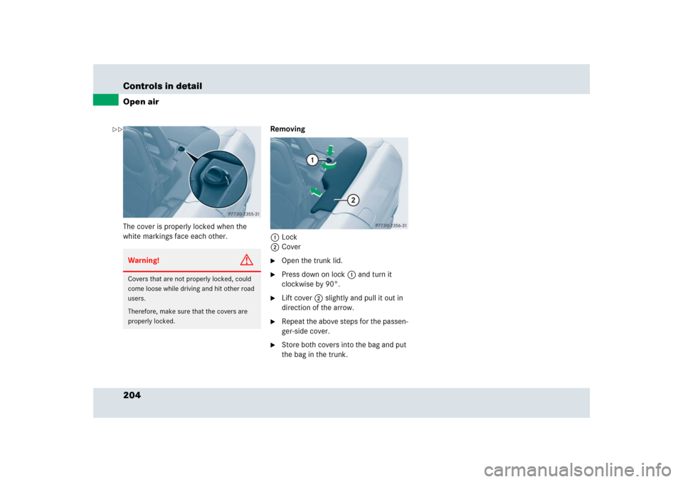
204 Controls in detailOpen airThe cover is properly locked when the
white markings face each other.Removing
1Lock
2Cover
�
Open the trunk lid.
�
Press down on lock1 and turn it
clockwise by 90°.
�
Lift cover2 slightly and pull it out in
direction of the arrow.
�
Repeat the above steps for the passen-
ger-side cover.
�
Store both covers into the bag and put
the bag in the trunk.
Warning!
G
Covers that are not properly locked, could
come loose while driving and hit other road
users.
Therefore, make sure that the covers are
properly locked.
��
Page 216 of 426

216 Controls in detailUseful featuresThe speaker volume of a Tele Aid call can
be adjusted when using the volume control
on the audio system or on the multifunc-
tion steering wheel. To raise, turn the rota-
ry volume control on the audio system
clockwise or press buttonæ on the
multifunction steering wheel. To lower,
turn the rotary volume control on the audio
system control counterclockwise or press
buttonç on the multifunction steering
wheel.System self-check
The system performs a self-test after you
have switched on the ignition.Emergency calls
An emergency call is initiated
automatically following an accident in
Emergency Tensioning Devices (ETDs) or
air bags have deployed.
An emergency call can also be initiated
manually (
�page 217).
Once the emergency call is in progress, the
indicator lamp in the SOS button will begin
to flash. The message
Connecting Call
appears in the multifunction display. When
the connection is established, you see the
message
Call Connected
in the multifunc-
tion display.
All information relevant to the emergency,
such as the location of the vehicle (deter-
mined by the GPS satellite location sys-
tem), vehicle model, identification number
and color are generated.
Warning!
G
If the indicator lamps in the SOS button, in
the Roadside Assistance button, and/or in
the Information button do not come on dur-
ing the system self-check, or if any of these
indicators remain illuminated continuously
in red and/or the message
Tele Aid
Inoperative
is displayed in the multifunc-
tion display after the system self-check, a
malfunction in the system has been
detected.
If a malfunction is indicated as outlined
above, the system may not operate as ex-
pected. In case of an emergency, help will
have to be summoned by other means. Have
the system checked at the nearest
Mercedes-Benz Center or contact the Re-
sponse Center at 1-800-756-9018 (in the
USA) or 1-888-923-8367 (in Canada) as
soon as possible.
Page 247 of 426

247 Operation
At the gas station
�At the gas station
RefuelingThe fuel filler flap is located on the
right-hand side of the vehicle towards the
rear. Locking/unlocking the vehicle with
the SmartKey automatically locks/unlocks
the fuel filler flap.
1Fuel filler flap
2Fuel filler cap
3Recess
�
Remove the SmartKey from the starter
switch.
�
Open the fuel filler flap 1 by pushing
at the point indicated by arrow.
The fuel filler flap opens.
�
Turn fuel filler cap2 counterclock-
wise and hold on to it until possible
pressure is released.
�
Take off cap and set it in the recess3
on the fuel filler flap.
�
To prevent fuel vapors from escaping
into open air, fully insert filler nozzle
unit.
�
Only use premium unleaded gasoline
with a minimum Posted Octane Rating
of 91 (average of 96 RON/86 MON).
�
Only fill your tank until the filler nozzle
unit cuts out – do not top off or
overfill.
Warning!
G
Gasoline is highly flammable and poisonous.
It burns violently and can cause serious
personal injury.
Never allow sparks, flame or smoking
materials near gasoline!
Turn off the engine before refueling.
Whenever you are around gasoline, avoid
inhaling fumes and skin contact, extinguish
all smoking materials.
Direct skin contact with fuels and the inha-
lation of fuel vapors are damaging to your
health.
i
In case that the central locking system does
not release the fuel filler flap, or the opening
mechanism is clamping, notify Roadside Assis-
tance or an authorized Mercedes-Benz Center.
i
Information on gasoline quality can normal-
ly be found on the fuel pump. Please contact gas
station personnel in case labels on the pump
cannot be found.
��
Page 248 of 426

248 OperationAt the gas station�
Replace fuel filler cap by turning it
clockwise until it audibly engages.
�
Close the fuel filler flap until you hear
the latch close shut.
Check regularly and before a long trip
1Coolant
2Engine oil
3Brake fluid
Warning!
G
Overfilling of the fuel tank may create
pressure in the system which could cause a
gas discharge. This could cause the gas to
spray back out when removing the fuel
pump nozzle, which could cause personal
injury. i
Make sure to close the fuel filler flap before
locking your vehicle as the flap locking pin pre-
vents closing after you have locked the vehicle.
i
For more information on gasoline, see “Pre-
mium unleaded gasoline” (
�page 396), see “Fu-
el requirements” (
�page 397), or contact an
authorized Mercedes-Benz Center, or visit
www.mbusa.com (USA only).
Leaving the engine running and the fuel filler cap
open can cause theú malfunction indicator
lamp (USA only) or the± malfunction indica-
tor lamp (Canada only) to illuminate.
For more information, see “Practical hints”
(
�page 309).
i
Opening the hood, see (
�page 250).
��
Page 258 of 426
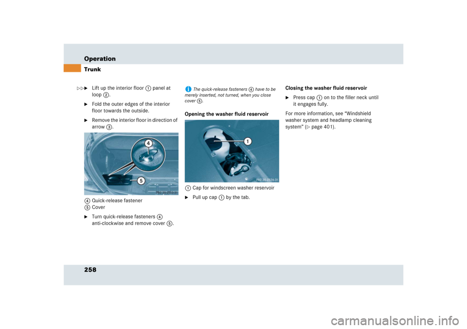
258 OperationTrunk�
Lift up the interior floor1 panel at
loop2.
�
Fold the outer edges of the interior
floor towards the outside.
�
Remove the interior floor in direction of
arrow3.
4Quick-release fastener
5Cover
�
Turn quick-release fasteners4
anti-clockwise and remove cover5.Opening the washer fluid reservoir
1Cap for windscreen washer reservoir
�
Pull up cap1 by the tab.Closing the washer fluid reservoir
�
Press cap1 on to the filler neck until
it engages fully.
For more information, see “Windshield
washer system and headlamp cleaning
system” (
�page 401).
i
The quick-release fasteners 4 have to be
merely inserted, not turned, when you close
cover 5.
��
Page 357 of 426
357 Practical hints
Unlocking in an emergency
�Unlocking in an emergency
Unlocking the vehicle
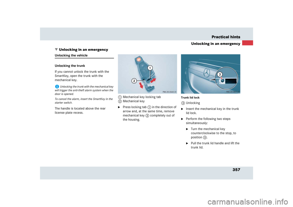
Unlocking the trunk
If you cannot unlock the trunk with the
SmartKey, open the trunk with the
mechanical key.
The handle is located above the rear
license plate recess.1Mechanical key locking tab
2Mechanical key
�
Press locking tab1 in the direction of
arrow and, at the same time, remove
mechanical key2 completely out of
the housing.
Trunk lid lock3Unlocking�
Insert the mechanical key in the trunk
lid lock.
�
Perform the following two steps
simultaneously:�
Turn the mechanical key
counterclockwise to the stop, to
position3.
�
Pull the trunk lid handle and lift the
trunk lid.
i
Unlocking the trunk with the mechanical key
will trigger the anti-theft alarm system when the
door is opened.
To cancel the alarm, insert the SmartKey in the
starter switch.
Page 375 of 426
.
1Towing eye bolt
�
Remove cover from the access ho")
375 Practical hints
Towing the vehicle
Installing/reinstalling towing eye bolt�
Take the towing eye bolt1 from its
storage compartment (
�page 356).
1Towing eye bolt
�
Remove cover from the access hole.
�
Screw towing eye bolt1 clockwise in
to its stop.
�
Remove the towing eye bolt when you
no longer need it. To do this, carry out
the above steps in reverse order.
Points to bear in mind�
The vehicle must not be tow-started.
�
If the vehicle is to be towed, only tow it
with all wheels on the ground.
�
If the vehicle has suffered transmission
damage, only tow it with the propeller
shaft disconnected.
�
Before towing the vehicle, make sure
the battery is connected and charged.
Otherwise you will not be able to switch
on the ignition and move the selector
lever to neutral positionN. There will
then be no power assistance when
steering and braking.
Transporting the vehicle
The towing eye bolt can be used to pull the
vehicle onto a trailer or transporter for
transporting purposes.�
Switch on the ignition (
�page 40).
�
Move the selector lever to neutral
positionN.
!
Only secure the tow bar to the towing eye
bolt. The vehicle could otherwise be damaged.
!
Your vehicle is equipped with a front towing
eye bolt only (
�page 375).
You cannot tow other vehicles with your vehicle.
!
Due to the low clearance height of the SLR,
care must be taken when loading and unloading
from a transporter to avoid damaging the vehicle
body work.
To secure the vehicle, only tie it down by the
wheels or tires. Otherwise it could be damaged.