2009 MERCEDES-BENZ E-CLASS ESTATE tow bar
[x] Cancel search: tow barPage 14 of 373
Loss
............................................... 297
Malfunction ................................... .296
Modifying the programming .............71
KEYLESS GO
Button .............................................. 75
Changing the battery .....................304
Checking the battery .....................304
Convenience closing ......................103
Display message ............................ 274
Locking ............................................ 70
Malfunction ................................... .296
Starting the engine ........................105
Unlocking ......................................... 70
Key positions
Key .................................................. 75
KEYLESS GO .................................... 75
Kickdown ........................... 114, 116, 117 L
Lamps see Warning and indicator lamps
Lane-change assistant
see Blind Spot Assist .....................167
Lane Keeping Assist .......................... 169
Activating/deactivating (on-
board computer) ............................ 130
Display message ............................ 258
Lane package ..................................... 167
Lashing eyelets ................................. 197
Licence plate lighting Display message ............................ 272
Lighting
see Lights
Lights
Active light function .........................97
Automatic headlamp mode ..............94
Combination switch .........................93
Cornering light function ...................97
Daytime driving lights ......................94
Dipped-beam headlamps .................94
Display message ............................ 273
Foglamps ................................... 94, 98
Hazard warning lamps .....................96
Headlamp flasher ............................. 94
Headlamp range .............................. 98
Light switch ..................................... 93
Main-beam headlamps ..................... 95 Motorway mode
............................... 98
Rear foglamp ................................... 95
Switching surround lighting on/
off (on-board computer) ................. 134
Switching the daytime driving
lights on/off (on-board computer) .132
Switching the exterior lighting
delayed switch-off on/off (on-
board computer) ............................ 134
Switching the Intelligent Light
System on/off (on-board com-
puter) ............................................. 133
Turn signals ..................................... 96
LIM indicator lamp
Cruise control ................................ 138
Distronic Plus ................................ 141
Variable Speedtronic .....................149
Loading guidelines ............................187
Loading sill protector ........................ 205
Locking Automatic ........................................ 72
Emergency locking ........................299
From the inside (central locking
button) ............................................. 71
Luggage compartment enlarge-
ment ................................................... 196
Luggage compartment floor stowage well, unde r....................... 204
Luggage cover ................................... 198
Luggage holder (EASY-PACK load-
securing kit) ....................................... 203
Luggage net Front-passenger footwell ...............193
Lumbar support ................................... 78
4-way ............................................... 78
Luxury head restraint .........................81 M
Main-beam headlamps Adaptive Highbeam Assist .............133
Display message .................... 253, 272
Maintenance
Battery ........................................... 319
Manual drive program ..............115, 116
Manual transmission ........................110
Massage function (PULSE) .................81 Index
11 212_AKB; 2; 4, en-GB
mkalafa,
Version: 2.11.8.1 2009-05-05T14:17:16+02:00 - Seite 11Dateiname: 6515346702_buchblock.pdf; erzeugt am 07. May 2009 14:15:27; WK
Page 161 of 373
Front sensors
Centre Approximately 100 cm
Corners Approximately 60 cm
Rear sensors
Centre Approximately 120 cm
Corners Approximately 80 cm
!
When parking, pay particular attention to
objects above or below the sensors, such
as flower pots or trailer towbars. PARK-
TRONIC does not detect such objects when
they are in the immediate vicinity of the
vehicle. You could damage the vehicle or
the objects.
Ultrasonic sources such as an automatic
car wash, a lorry's compressed-air brakes
or a pneumatic drill could cause PARK-
TRONIC to malfunction.
Minimum distance Centre Approximately 20 cm
Corners Approximately 15 cm
If there is an obstacle within this range, all
warning displays light up and a tone sounds.
If the distance falls below the minimum clear-
ance, it may no longer be shown.
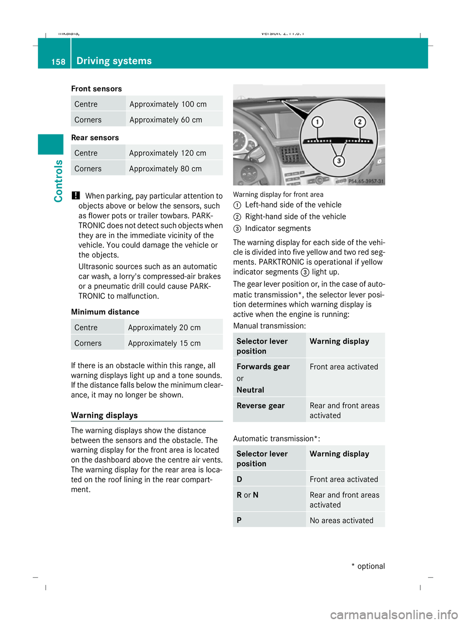
Warning displays
The warning displays show the distance
between the sensors and the obstacle. The
warning display for the front area is located
on the dashboard above the centre air vents.
The warning display for the rear area is loca-
ted on the roof lining in the rear compart-
ment. Warning display for front area
:
Left-hand side of the vehicle
; Right-hand side of the vehicle
= Indicator segments
The warning display for each side of the vehi-
cle is divided into five yellow and two red seg-
ments. PARKTRONIC is operational if yellow
indicator segments =light up.
The gear lever position or, in the case of auto-
matic transmission*, the selector lever posi-
tion determines which warning display is
active when the engine is running:
Manual transmission: Selector lever
position Warning display
Forwards gear
or
Neutral
Front area activated
Reverse gear
Rear and front areas
activated
Automatic transmission*:
Selector lever
position Warning display
D
Front area activated
R
or N Rear and front areas
activated
P
No areas activated158
Driving systemsControls
* optional
212_AKB; 2; 4, en-GB
mkalafa
,V ersion: 2.11.8.1
2009-05-05T14:17:16+02:00 - Seite 158
Dateiname: 6515346702_buchblock.pdf; erzeugt am 07. May 2009 14:16:23; WK
Page 229 of 373
dent. Therefore, you should regularly check
the pressure of all the tyres, particularly prior
to long trips, and correct the pressure as nec-
essary.
To test tyre pressure, use a suitable pressure
gauge. The outer appearance of a tyre does
not permit any reliable conclusion about the
tyre pressure. On vehicles fitted with the elec-
tronic tyre pressure monitor*, the tyre pres-
sure can be checked in the on-board com-
puter. G
Risk of accident
Do not fit anything else to the tyre valve other
than the standard valve cap. In particular, ret-
rofitted tyre pressure monitors which are
screwed on to the valve may overload it and
cause it to fail. Due to their design, the valve
is kept open continuously, which may lead to
air loss. G
Risk of accident
Should the tyre pressure drop repeatedly:
R check the tyre for foreign bodies.
R check whether the wheel is losing air or the
valve is leaking.
R make sure that only a valve cap approved
by Mercedes-Benz is fitted on the tyre
valve.
Tyre pressures that are too low have a nega-
tive effect on vehicle safety, which could lead
to your causing an accident.
If possible, you should only correct tyre pres-
sures when the tyres are cold. Depending on
the ambient temperature, the speed you are
driving at and the load on the tyres, the tyre
temperature and thus the tyre pressure may
change by approximately 0.1 bar per 10 †.
Take this into account when checking the
pressure of warm tyres and only correct it if
it is too low for the current operating condi-
tions. Driving with tyre pressure that is too high or
too low can:
R
shorten the service life of the tyres
R increase the likelihood of tyre damage
R have a negative effect on handling charac-
teristics (e.g. by causing aquaplaning)
Also check the pressure of the "Minispare"
emergency spare wheel*. H
Environmental note
Check the tyre pressure regularly, at least
every 14 days.
Speeds up to 210 km/h:
Despite the values stated on the tyre pressure
information label (fuel filler flap), for speeds
up to 210 km/h andwith 16" or 17" tyres,
the values stated can be reduced as follows,
without a reduction in safety:
Saloon: -0.3 bar / (-4 psi)
Estate: -0.2 bar (-3 psi)
This does not apply to vehicles towing a
trailer.
This improves the ride comfort of your vehi-
cle; however, the fuel consumption may
increase slightly. Tyre pressure loss warning
While the vehicle is in motion, the tyre pres-
sure loss warning system monitors the set
tyre pressure using the rotational speed of
the wheels. This enables the system to detect
significant pressure loss in a tyre. If the speed
of rotation of a wheel changes as a result of
a loss of pressure, a corresponding warning
message will appear in the multi-function dis-
play. G
Risk of accident
The tyre pressure loss warning system does
not warn you of an incorrectly set tyre pres-
sure. The table on the inside of the fuel filler
flap will help you decide whether the tyre
pressures should be corrected. 226
Tyres and wheelsOperation
* optional
212_AKB; 2; 4, en-GB
mkalafa,
Version: 2.11.8.1 2009-05-05T14:17:16+02:00 - Seite 226
Dateiname: 6515346702_buchblock.pdf; erzeugt am 07. May 2009 14:16:57; WK
Page 238 of 373
X
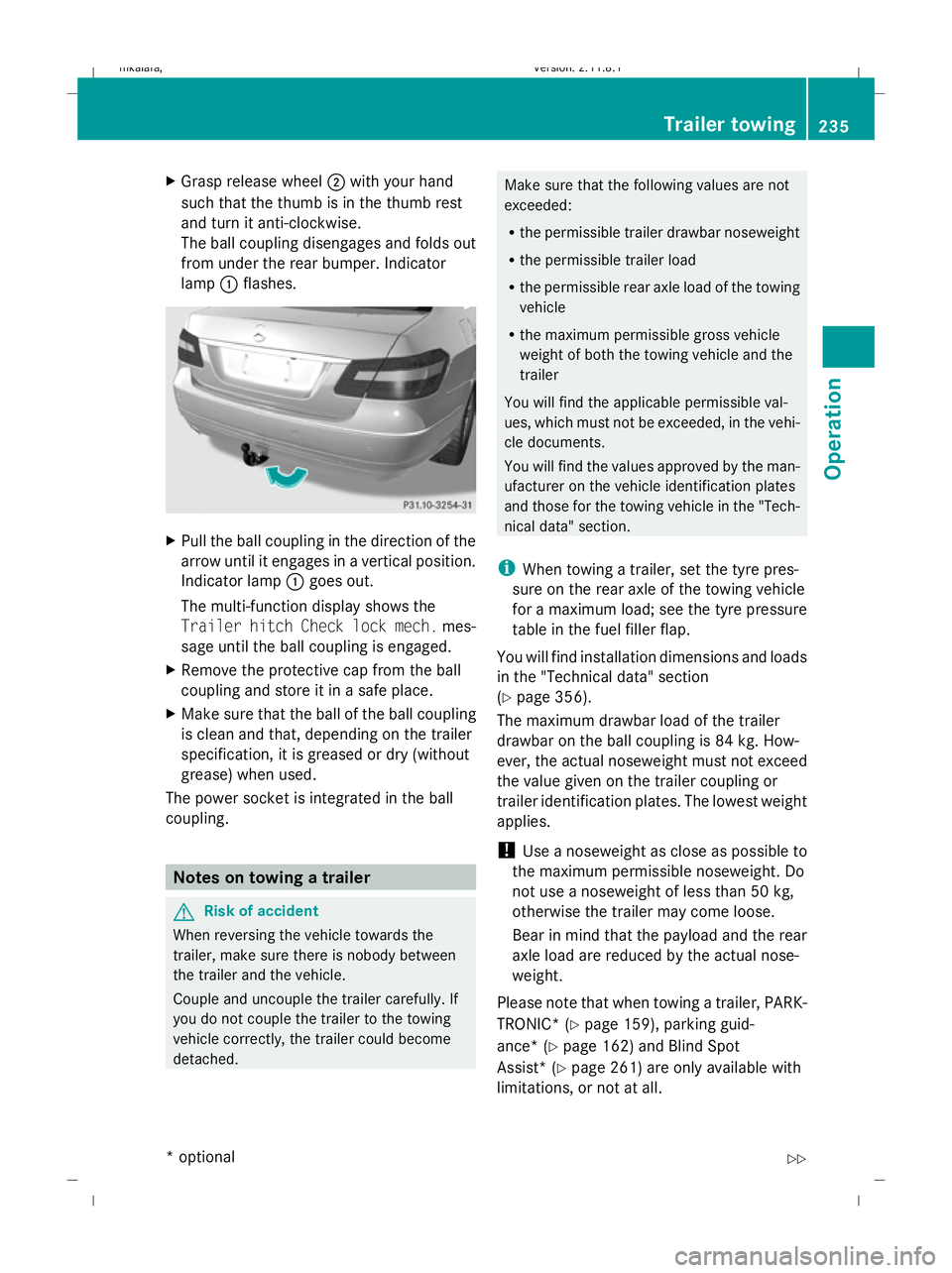
Grasp release wheel ;with your hand
such that the thumb is in the thumb rest
and turn it anti-clockwise.
The ball coupling disengages and folds out
from under the rear bumper. Indicator
lamp :flashes. X
Pull the ball coupling in the direction of the
arrow until it engages in a vertical position.
Indicator lamp :goes out.
The multi-function display shows the
Trailer hitch Check lock mech. mes-
sage until the ball coupling is engaged.
X Remove the protective cap from the ball
coupling and store it in a safe place.
X Make sure that the ball of the ball coupling
is clean and that, depending on the trailer
specification, it is greased or dry (without
grease) when used.
The power socket is integrated in the ball
coupling. Notes on towing a trailer
G
Risk of accident
When reversing the vehicle towards the
trailer, make sure there is nobody between
the trailer and the vehicle.
Couple and uncouple the trailer carefully. If
you do not couple the trailer to the towing
vehicle correctly, the trailer could become
detached. Make sure that the following values are not
exceeded:
R
the permissible trailer drawbar noseweight
R the permissible trailer load
R the permissible rear axle load of the towing
vehicle
R the maximum permissible gross vehicle
weight of both the towing vehicle and the
trailer
You will find the applicable permissible val-
ues, which must not be exceeded, in the vehi-
cle documents.
You will find the values approved by the man-
ufacturer on the vehicle identification plates
and those for the towing vehicle in the "Tech-
nical data" section.
i When towing a trailer, set the tyre pres-
sure on the rear axle of the towing vehicle
for a maximum load; see the tyre pressure
table in the fuel filler flap.
You will find installation dimensions and loads
in the "Technical data" section
(Y page 356).
The maximum drawbar load of the trailer
drawbar on the ball coupling is 84 kg. How-
ever, the actual noseweight must not exceed
the value given on the trailer coupling or
trailer identification plates. The lowest weight
applies.
! Use a noseweight as close as possible to
the maximum permissible noseweight. Do
not use a noseweight of less than 50 kg,
otherwise the trailer may come loose.
Bear in mind that the payload and the rear
axle load are reduced by the actual nose-
weight.
Please note that when towing a trailer, PARK-
TRONIC* ( Ypage 159), parking guid-
ance* (Y page 162) and Blind Spot
Assist* (Y page 261) are only available with
limitations, or not at all. Trailer towing
235Operation
* optional
212_AKB; 2; 4, en-GB
mkalafa
,V ersion: 2.11.8.1
2009-05-05T14:17:16+02:00 - Seite 235 Z
Dateiname: 6515346702_buchblock.pdf; erzeugt am 07. May 2009 14:16:59; WK
Page 239 of 373
i
On vehicles without level control, the
height of the ball coupling will alter accord-
ing to the load placed on the vehicle. If nec-
essary, use a trailer with a height-adjusta-
ble drawbar.
Coupling up a trailer G
Risk of injury
Do not disconnect a trailer with an engaged
overrun brake. Otherwise, your hand could
become trapped between the bumper and
trailer drawbar.
! Do not disconnect a trailer with an
engaged overrun brake. Otherwise, your
vehicle could be damaged by the rebound-
ing of the overrun brake.
X Position the trailer level behind the vehicle.
X Couple up the trailer.
X Establish the electrical connection
between the vehicle and the trailer.
Driving tips G
Risk of accident
If the Check trailer hitch locking
mechanism message appears in the multi-
function display while the vehicle is in motion,
pull over immediately and check whether the
ball coupling is correctly engaged.
i Observe the notes on ESP ®
trailer stabi-
lisation (Y page 60).
In Germany, the maximum permissible speed
for vehicle/trailer combinations depends on
the type of trailer and is either 80 km/h or
100 km/h. Before beginning the journey,
check the trailer's documents to see what the
maximum permitted speed is. G
Risk of accident
Always observe the maximum speed permit-
ted in Germany for vehicle/trailer combina-
tions, even in countries where higher speeds are permitted. This lowers the risk of an acci-
dent.
When towing a trailer, your vehicle's handling
characteristics will be different in comparison
to when driving without a trailer.
The vehicle/trailer combination:
R is heavier
R is restricted in its acceleration and gradi-
ent-climbing capability
R has an increased braking distance
R is affected more by strong crosswinds
R demands more sensitive steering
R consumes more fuel
On long and steep downhill gradients you
must select a lower gear in good time, or on
vehicles with automatic transmission*, select
shift range 1,2or 3.
i This also applies if you have activated
cruise control, Speedtronic or Distronic
Plus*.
This will use the braking effect of the engine,
so less braking will be required to maintain
the speed. This relieves the load on the brake
system and prevents the brakes from over-
heating and wearing too quickly. If you need
additional braking, depress the brake pedal
repeatedly rather than continuously. G
Risk of accident
Never depress the brake pedal continuously
while the vehicle is in motion, e.g. never cause
the brakes to rub by applying constant slight
pedal pressure. This causes the brake system
to overheat, increases the braking distance
and can lead to the brakes failing completely. 236
Trailer towingOperation
* optional
212_AKB; 2; 4, en-GB
mkalafa,
Version: 2.11.8.1 2009-05-05T14:17:16+02:00 - Seite 236
Dateiname: 6515346702_buchblock.pdf; erzeugt am 07. May 2009 14:16:59; WK
Page 315 of 373
If a pressure of 1.8 bar is not reached
after five minutes:
X Switch off and disconnect the electric air
pump and drive the vehicle forwards or
backwards approximately 10 m.
This distributes the TIREFIT more evenly.
X Pump up the tyre again. G
Risk of accident
If a pressure of 1.8 bar is not achieved after
five minutes, the tyre is too badly damaged.
Do not drive any further. Consult a qualified
specialist workshop which has the necessary
specialist knowledge and tools to carry out
the work required. Mercedes-Benz recom-
mends that you use a Mercedes-Benz Service
Centre for this purpose. In particular, work
relevant to safety or on safety-related sys-
tems must be carried out at a qualified spe-
cialist workshop.
When a tyre pressure of at least 1.8 bar
is reached:
X Press on/off switch ?on the electric air
pump to 0.
The electric air pump is switched off.
X Remove the TIREFIT kit from the wheel.
! After use, excess TIREFIT may run out of
the filler hose. This may cause stains.
Therefore, place the filler hose in the plastic
which contained the TIREFIT kit.
X Stow away the TIREFIT kit, the electric air
pump and the warning triangle.
X Pull away immediately.
X Stop after driving for approximately ten
minutes and check the tyre pressure with
the electric air pump. G
Risk of accident
If the tyre pressure is now lower than 1.3 bar,
the tyre is too badly damaged. Do not drive
any further. Consult a qualified specialist
workshop which has the necessary specialist
knowledge and tools to carry out the work required. Mercedes-Benz recommends that
you use a Mercedes-Benz Service Centre for
this purpose. In particular, work relevant to
safety or on safety-related systems must be
carried out at a qualified specialist workshop.
X If the tyre pressure is still at least 1.3 bar,
correct it (see fuel filler flap for values).
To increase the tyre pressure: switch on
the electric air pump.
To reduce the tyre pressure: open pres-
sure release screw Fon pressure
gauge G.
X Drive to the nearest workshop and have the
tyre changed there.
X Have the TIREFIT kit replaced as soon as
possible at a qualified specialist workshop,
e.g. at a Mercedes-Benz Service Centre. G
Risk of accident
Do not exceed the maximum speed of
80 km/h.
The "max. 80 km/h" label must be affixed in
the driver's field of vision.
The vehicle's handling characteristics may be
affected. H
Environmental note
Have the used TIREFIT kit disposed of profes-
sionally, e.g. at a Mercedes-Benz Service
Centre.
X Have the TIREFIT kit replaced every four
years at a qualified specialist workshop,
e.g. a Mercedes-Benz Service Centre. 312
Flat tyrePractical advice
212_AKB; 2; 4, en-GB
mkalafa
,V ersion: 2.11.8.1
2009-05-05T14:17:16+02:00 - Seite 312
Dateiname: 6515346702_buchblock.pdf; erzeugt am 07. May 2009 14:17:21; WK
Page 317 of 373
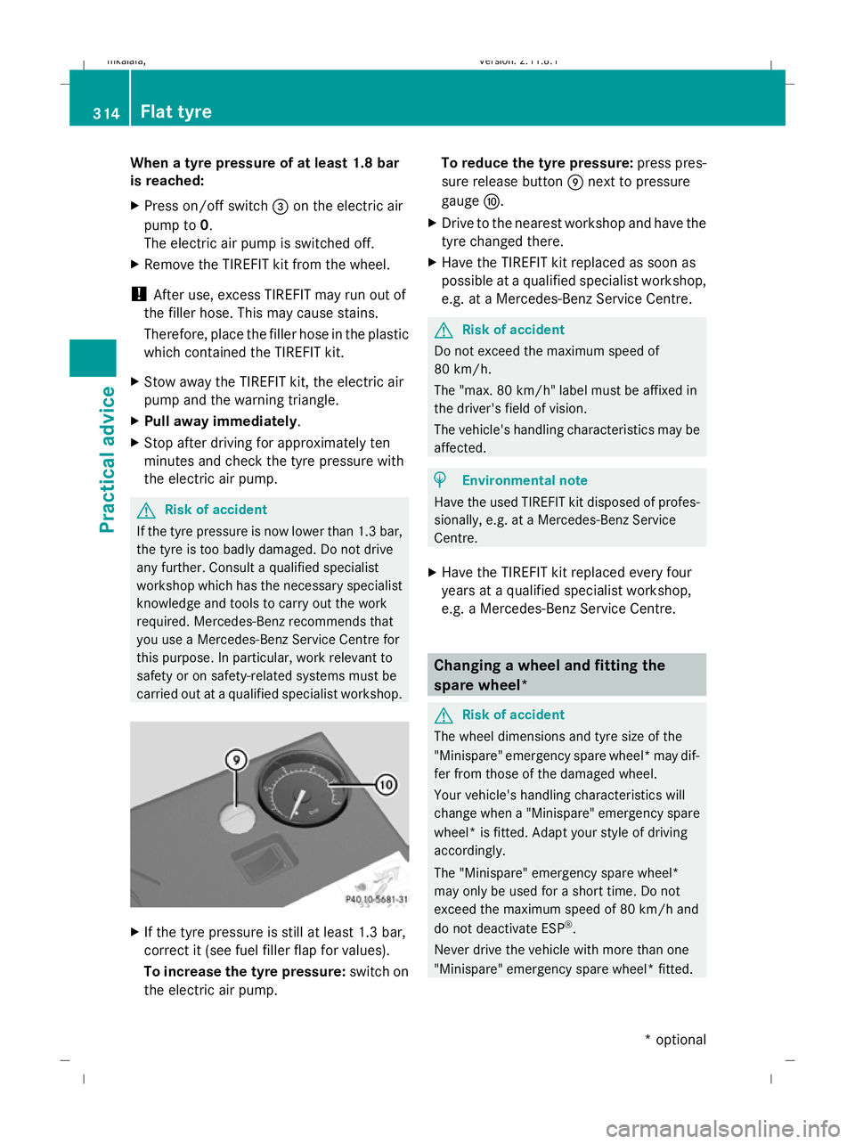
When a tyre pressure of at least 1.8 bar
is reached:
X Press on/off switch =on the electric air
pump to 0.
The electric air pump is switched off.
X Remove the TIREFIT kit from the wheel.
! After use, excess TIREFIT may run out of
the filler hose. This may cause stains.
Therefore, place the filler hose in the plastic
which contained the TIREFIT kit.
X Stow away the TIREFIT kit, the electric air
pump and the warning triangle.
X Pull away immediately.
X Stop after driving for approximately ten
minutes and check the tyre pressure with
the electric air pump. G
Risk of accident
If the tyre pressure is now lower than 1.3 bar,
the tyre is too badly damaged. Do not drive
any further. Consult a qualified specialist
workshop which has the necessary specialist
knowledge and tools to carry out the work
required. Mercedes-Benz recommends that
you use a Mercedes-Benz Service Centre for
this purpose. In particular, work relevant to
safety or on safety-related systems must be
carried out at a qualified specialist workshop. X
If the tyre pressure is still at least 1.3 bar,
correct it (see fuel filler flap for values).
To increase the tyre pressure: switch on
the electric air pump. To reduce the tyre pressure:
press pres-
sure release button Enext to pressure
gauge F.
X Drive to the nearest workshop and have the
tyre changed there.
X Have the TIREFIT kit replaced as soon as
possible at a qualified specialist workshop,
e.g. at a Mercedes-Benz Service Centre. G
Risk of accident
Do not exceed the maximum speed of
80 km/h.
The "max. 80 km/h" label must be affixed in
the driver's field of vision.
The vehicle's handling characteristics may be
affected. H
Environmental note
Have the used TIREFIT kit disposed of profes-
sionally, e.g. at a Mercedes-Benz Service
Centre.
X Have the TIREFIT kit replaced every four
years at a qualified specialist workshop,
e.g. a Mercedes-Benz Service Centre. Changing a wheel and fitting the
spare wheel*
G
Risk of accident
The wheel dimensions and tyre size of the
"Minispare" emergency spare wheel* may dif-
fer from those of the damaged wheel.
Your vehicle's handling characteristics will
change when a "Minispare" emergency spare
wheel* is fitted. Adapt your style of driving
accordingly.
The "Minispare" emergency spare wheel*
may only be used for a short time. Do not
exceed the maximum speed of 80 km/h and
do not deactivate ESP ®
.
Never drive the vehicle with more than one
"Minispare" emergency spare wheel* fitted. 314
Flat tyrePractical advice
* optional
212_AKB; 2; 4, en-GB
mkalafa,
Version: 2.11.8.1 2009-05-05T14:17:16+02:00 - Seite 314
Dateiname: 6515346702_buchblock.pdf; erzeugt am 07. May 2009 14:17:22; WK
Page 327 of 373
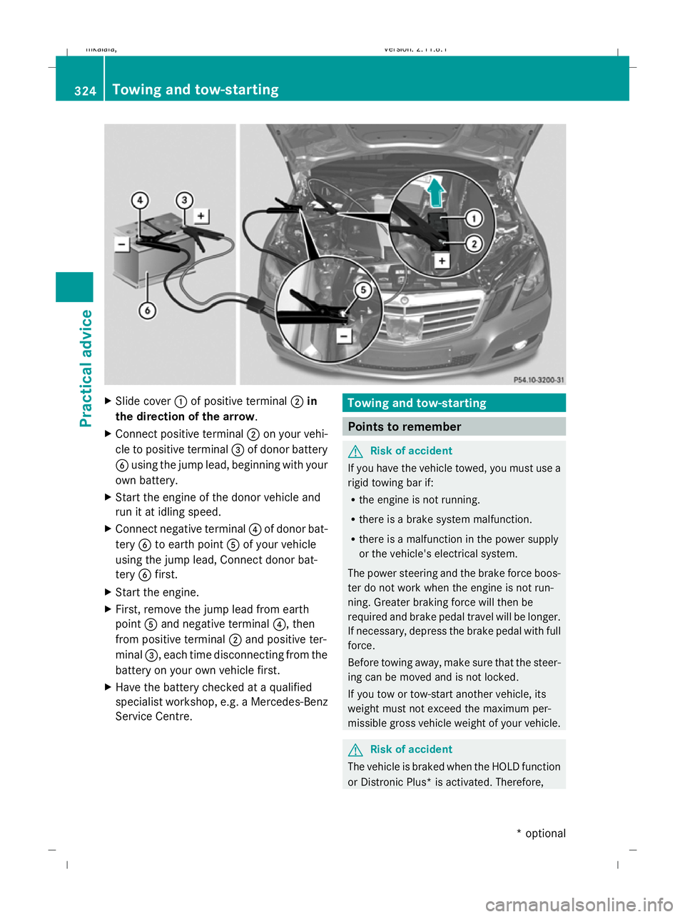
X
Slide cover :of positive terminal ;in
the direction of the arrow .
X Connect positive terminal ;on your vehi-
cle to positive terminal =of donor battery
B using the jump lead, beginning with your
own battery.
X Start the engine of the donor vehicle and
run it at idling speed.
X Connect negative terminal ?of donor bat-
tery Bto earth point Aof your vehicle
using the jump lead, Connect donor bat-
tery Bfirst.
X Start the engine.
X First, remove the jump lead from earth
point Aand negative terminal ?, then
from positive terminal ;and positive ter-
minal =, each time disconnecting from the
battery on your own vehicle first.
X Have the battery checked at a qualified
specialist workshop, e.g. a Mercedes-Benz
Service Centre. Towing and tow-starting
Points to remember
G
Risk of accident
If you have the vehicle towed, you must use a
rigid towing bar if:
R the engine is not running.
R there is a brake system malfunction.
R there is a malfunction in the power supply
or the vehicle's electrical system.
The power steering and the brake force boos-
ter do not work when the engine is not run-
ning. Greater braking force will then be
required and brake pedal travel will be longer.
If necessary, depress the brake pedal with full
force.
Before towing away, make sure that the steer-
ing can be moved and is not locked.
If you tow or tow-start another vehicle, its
weight must not exceed the maximum per-
missible gross vehicle weight of your vehicle. G
Risk of accident
The vehicle is braked when the HOLD function
or Distronic Plus* is activated. Therefore, 324
Towing and tow-startingPractical advice
* optional
212_AKB; 2; 4, en-GB
mkalafa
,V ersion: 2.11.8.1
2009-05-05T14:17:16+02:00 - Seite 324
Dateiname: 6515346702_buchblock.pdf; erzeugt am 07. May 2009 14:17:27; WK