2009 MERCEDES-BENZ E-CLASS ESTATE buttons
[x] Cancel search: buttonsPage 181 of 373
Setting the air distribution
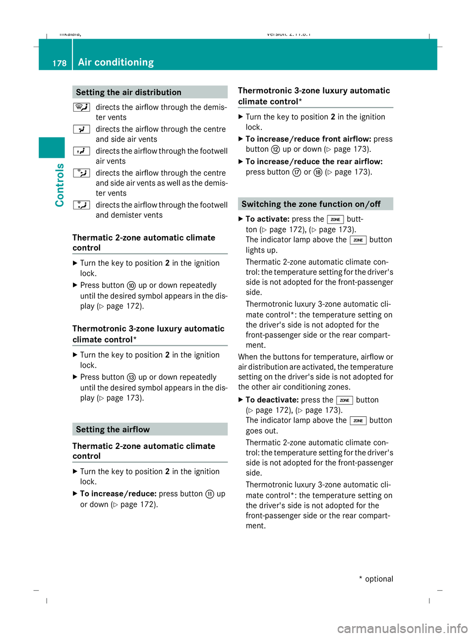
¯ directs the airflow through the demis-
ter vents
P directs the airflow through the centre
and side air vents
O directs the airflow through the footwell
air vents
b directs the airflow through the centre
and side air vents as well as the demis-
ter vents
a directs the airflow through the footwell
and demister vents
Thermatic 2-zone automatic climate
control X
Turn the key to position 2in the ignition
lock.
X Press button Fup or down repeatedly
until the desired symbol appears in the dis-
play (Y page 172).
Thermotronic 3-zone luxury automatic
climate control* X
Turn the key to position 2in the ignition
lock.
X Press button Iup or down repeatedly
until the desired symbol appears in the dis-
play (Y page 173). Setting the airflow
Thermatic 2-zone automatic climate
control X
Turn the key to position 2in the ignition
lock.
X To increase/reduce: press buttonGup
or down (Y page 172). Thermotronic 3-zone luxury automatic
climate control* X
Turn the key to position 2in the ignition
lock.
X To increase/reduce front airflow: press
button Hup or down (Y page 173).
X To increase/reduce the rear airflow:
press button MorN (Ypage 173). Switching the zone function on/off
X To activate: press theábutt-
ton (Y page 172), (Y page 173).
The indicator lamp above the ábutton
lights up.
Thermatic 2-zone automatic climate con-
trol: the temperature setting for the driver's
side is not adopted for the front-passenger
side.
Thermotronic luxury 3-zone automatic cli-
mate control*: the temperature setting on
the driver's side is not adopted for the
front-passenger side or the rear compart-
ment.
When the buttons for temperature, airflow or
air distribution are activated, the temperature
setting on the driver's side is not adopted for
the other air conditioning zones.
X To deactivate: press theábutton
(Y page 172), (Y page 173).
The indicator lamp above the ábutton
goes out.
Thermatic 2-zone automatic climate con-
trol: the temperature setting for the driver's
side is not adopted for the front-passenger
side.
Thermotronic luxury 3-zone automatic cli-
mate control*: the temperature setting on
the driver's side is not adopted for the
front-passenger side or the rear compart-
ment. 178
Air conditioningControls
* optional
212_AKB; 2; 4, en-GB
mkalafa,
Version: 2.11.8.1 2009-05-05T14:17:16+02:00 - Seite 178
Dateiname: 6515346702_buchblock.pdf; erzeugt am 07. May 2009 14:16:30; WK
Page 186 of 373
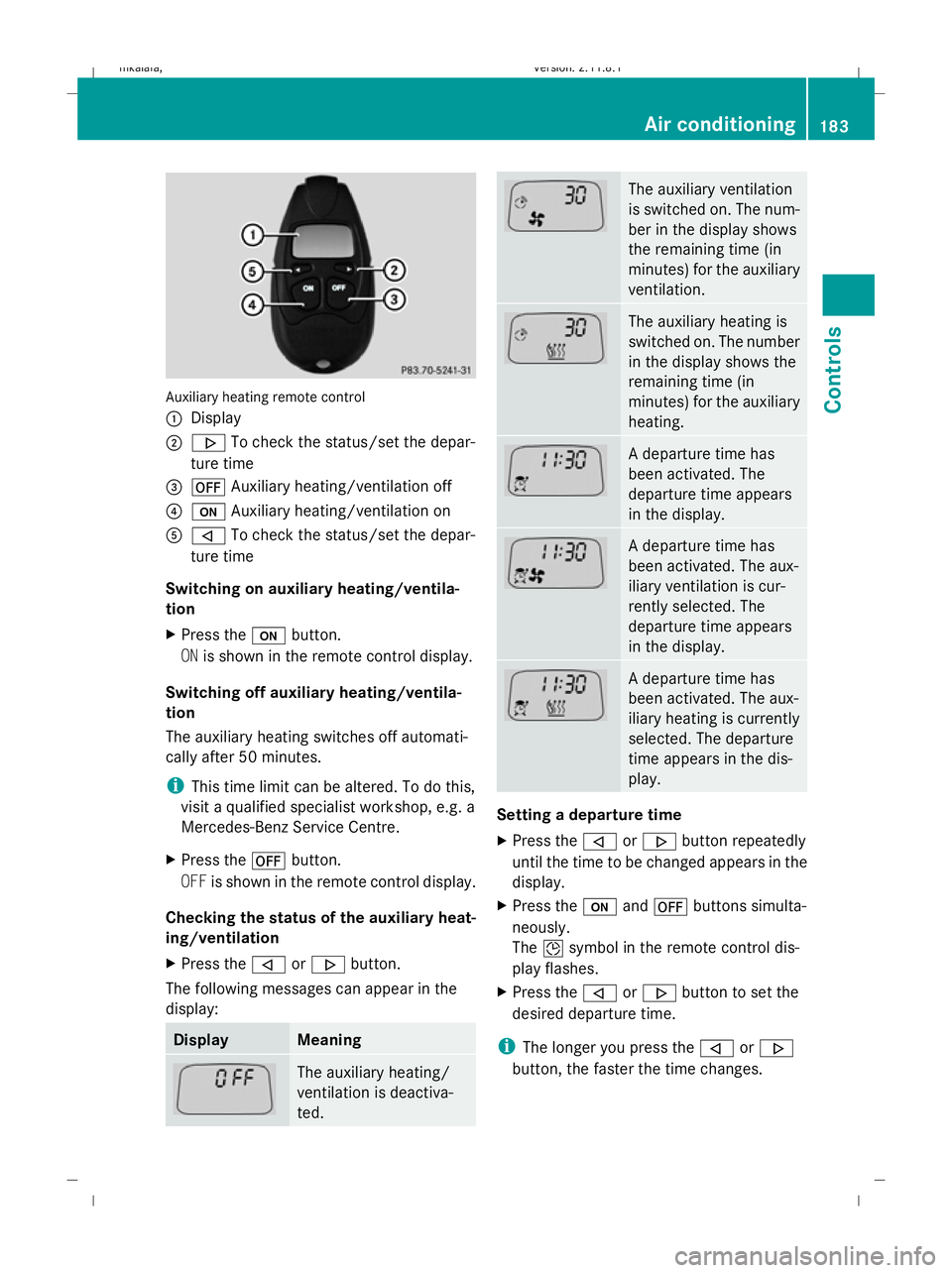
Auxiliary heating remote control
:
Display
; . To check the status/set the depar-
ture time
= ^ Auxiliary heating/ventilation off
? u Auxiliary heating/ventilation on
A , To check the status/set the depar-
ture time
Switching on auxiliary heating/ventila-
tion
X Press the ubutton.
ON is shown in the remote control display.
Switching off auxiliary heating/ventila-
tion
The auxiliary heating switches off automati-
cally after 50 minutes.
i This time limit can be altered. To do this,
visit a qualified specialist workshop, e.g. a
Mercedes-Benz Service Centre.
X Press the ^button.
OFF is shown in the remote control display.
Checking the status of the auxiliary heat-
ing/ventilation
X Press the ,or. button.
The following messages can appear in the
display: Display Meaning
The auxiliary heating/
ventilation is deactiva-
ted. The auxiliary ventilation
is switched on. The num-
ber in the display shows
the remaining time (in
minutes) for the auxiliary
ventilation.
The auxiliary heating is
switched on. The number
in the display shows the
remaining time (in
minutes) for the auxiliary
heating.
A departure time has
been activated. The
departure time appears
in the display.
A departure time has
been activated. The aux-
iliary ventilation is cur-
rently selected. The
departure time appears
in the display.
A departure time has
been activated. The aux-
iliary heating is currently
selected. The departure
time appears in the dis-
play.
Setting a departure time
X
Press the ,or. button repeatedly
until the time to be changed appears in the
display.
X Press the uand^ buttons simulta-
neously.
The Îsymbol in the remote control dis-
play flashes.
X Press the ,or. button to set the
desired departure time.
i The longer you press the ,or.
button, the faster the time changes. Air conditioning
183Controls
212_AKB; 2; 4, en-GB
mkalafa,V ersion: 2.11.8.1
2009-05-05T14:17:16+02:00 - Seite 183 Z
Dateiname: 6515346702_buchblock.pdf; erzeugt am 07. May 2009 14:16:32; WK
Page 187 of 373
X
Press the uand^ buttons simulta-
neously.
The new departure time is stored.
Activating a set departure time
X Press the ,or. button repeatedly
until the desired departure time appears in
the display.
X Press the ubutton.
The Ísymbol and the departure time
appear in the display.
Deactivating a set departure time
X Press the ,or. button.
The status of the auxiliary heating is shown
in the display.
X Press the .button.
The first departure time stored appears in
the display.
X Press the ^button.
The display message OFFappears in the
display. Sliding sunroof
General notes
G
Risk of injury
Make sure that nobody can become trapped
when closing the sliding sunroof. If there is a
risk of entrapment, release the switch and
push it briefly in any direction to stop the slid-
ing sunroof. G
Risk of injury
Children could injure themselves if they oper-
ate the sliding sunroof.
Never leave children unsupervised in the vehi-
cle. Always take the key with you when leaving
the vehicle, even if you are only leaving it for
a short time. G
Risk of injury
The glass in the panorama sunroof could
break in an accident. If you are not wearing a seat belt, there is a risk that you could be
thrown through the opening in the event of the
vehicle overturning. Therefore, always wear a
seat belt to reduce the risk of injuries.
! Only open the panorama sliding sunroof
if it is free of snow and ice. Otherwise, mal-
functions may occur.
Do not allow anything to protrude from the
sliding sunroof. The seals could otherwise
be damaged.
i When the sliding sunroof is open, apart
from the normal airflow noises resonance
noises may also occur. They are caused by
minor pressure fluctuations in the vehicle
interior. Change the position of the sliding
sunroof or open a side window slightly to
reduce or eliminate these noises.
i Related topics:
R convenience opening from the out-
side (Y page 102) or from the inside
(Y page 180)
R convenience closing from the out-
side (Y page 102) or from the inside
(Y page 180)
R automatic closing of the sliding sunroof
(PRE-SAFE) (Y page 42) 184
Sliding sunroofControls
212_AKB; 2; 4, en-GB
mkalafa,
Version: 2.11.8.1 2009-05-05T14:17:16+02:00 - Seite 184
Dateiname: 6515346702_buchblock.pdf; erzeugt am 07. May 2009 14:16:32; WK
Page 213 of 373
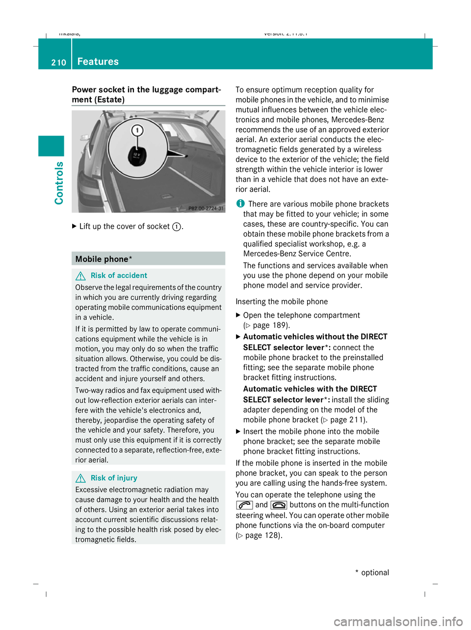
Power socket in the luggage compart-
ment (Estate) X
Lift up the cover of socket :.Mobile phone*
G
Risk of accident
Observe the legal requirements of the country
in which you are currently driving regarding
operating mobile communications equipment
in a vehicle.
If it is permitted by law to operate communi-
cations equipment while the vehicle is in
motion, you may only do so when the traffic
situation allows. Otherwise, you could be dis-
tracted from the traffic conditions, cause an
accident and injure yourself and others.
Two-way radios and fax equipment used with-
out low-reflection exterior aerials can inter-
fere with the vehicle's electronics and,
thereby, jeopardise the operating safety of
the vehicle and your safety. Therefore, you
must only use this equipment if it is correctly
connected to a separate, reflection-free, exte-
rior aerial. G
Risk of injury
Excessive electromagnetic radiation may
cause damage to your health and the health
of others. Using an exterior aerial takes into
account current scientific discussions relat-
ing to the possible health risk posed by elec-
tromagnetic fields. To ensure optimum reception quality for
mobile phones in the vehicle, and to minimise
mutual influences between the vehicle elec-
tronics and mobile phones, Mercedes-Benz
recommends the use of an approved exterior
aerial. An exterior aerial conducts the elec-
tromagnetic fields generated by a wireless
device to the exterior of the vehicle; the field
strength within the vehicle interior is lower
than in a vehicle that does not have an exte-
rior aerial.
i
There are various mobile phone brackets
that may be fitted to your vehicle; in some
cases, these are country-specific. You can
obtain these mobile phone brackets from a
qualified specialist workshop, e.g. a
Mercedes-Benz Service Centre.
The functions and services available when
you use the phone depend on your mobile
phone model and service provider.
Inserting the mobile phone
X Open the telephone compartment
(Y page 189).
X Automatic vehicles without the DIRECT
SELECT selector lever*: connect the
mobile phone bracket to the preinstalled
fitting; see the separate mobile phone
bracket fitting instructions.
Automatic vehicles with the DIRECT
SELECT selector lever *:install the sliding
adapter depending on the model of the
mobile phone bracket (Y page 211).
X Insert the mobile phone into the mobile
phone bracket; see the separate mobile
phone bracket fitting instructions.
If the mobile phone is inserted in the mobile
phone bracket, you can speak to the person
you are calling using the hands-free system.
You can operate the telephone using the
6 and~ buttons on the multi-function
steering wheel. You can operate other mobile
phone functions via the on-board computer
(Y page 128). 210
FeaturesControls
* optional
212_AKB; 2; 4, en-GB
mkalafa,
Version: 2.11.8.1 2009-05-05T14:17:16+02:00 - Seite 210
Dateiname: 6515346702_buchblock.pdf; erzeugt am 07. May 2009 14:16:51; WK
Page 214 of 373
When you take the key out of the ignition lock,
the mobile phone stays on but you can no
longer use the hands-free system.
If you are making a call and you would like to
take the key out of the ignition lock, first
remove the mobile phone from the bracket.
Otherwise, the call will be ended.
Sliding adapter for the mobile phone
bracket (automatic vehicles with
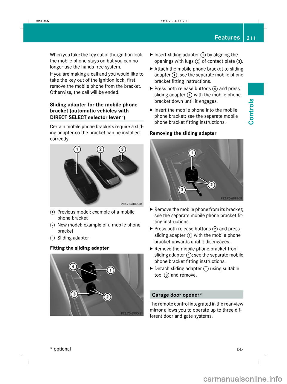
DIRECT SELECT selector lever*) Certain mobile phone brackets require a slid-
ing adapter so the bracket can be installed
correctly.
:
Previous model: example of a mobile
phone bracket
; New model: example of a mobile phone
bracket
= Sliding adapter
Fitting the sliding adapter X
Insert sliding adapter :by aligning the
openings with lugs ;of contact plate =.
X Attach the mobile phone bracket to sliding
adapter :; see the separate mobile phone
bracket fitting instructions.
X Press both release buttons 4and press
sliding adapter :with the mobile phone
bracket down until it engages.
X Insert the mobile phone into the mobile
phone bracket; see the separate mobile
phone bracket fitting instructions.
Removing the sliding adapter X
Remove the mobile phone from its bracket;
see the separate mobile phone bracket fit-
ting instructions.
X Press both release buttons ;and press
sliding adapter :with the mobile phone
bracket upwards until it disengages.
X Remove the mobile phone bracket from
sliding adapter :; see the separate mobile
phone bracket fitting instructions.
X Detach sliding adapter :using suitable
tool =and remove. Garage door opener*
The remote control integrated in the rear-view
mirror allows you to operate up to three dif-
ferent door and gate systems. Features
211Controls
* optional
212_AKB; 2; 4, en-GB
mkalafa,
Version: 2.11.8.1 2009-05-05T14:17:16+02:00 - Seite 211 Z
Dateiname: 6515346702_buchblock.pdf; erzeugt am 07. May 2009 14:16:52; WK
Page 215 of 373
i
The garage door opener is only available
for certain countries. Observe the legal
requirements in all countries concerned.
The HomeLink ®
garage door opener is
compatible with most European garage and
gate opener drives. More information on
HomeLink ®
and/or compatible products is
available from:
R any Mercedes-Benz Service Centre
R the HomeLink ®
hotline
(0) 08000 466 354 65 (free of charge) or
+49 (0) 6838 907-277 (charges apply)
R the Internet: www.homelink.com G
Risk of accident
Only press the transmitter button on the inte-
grated remote control if there are no persons
or objects present within the sweep of the
garage door. Persons could otherwise be
injured as the door moves.
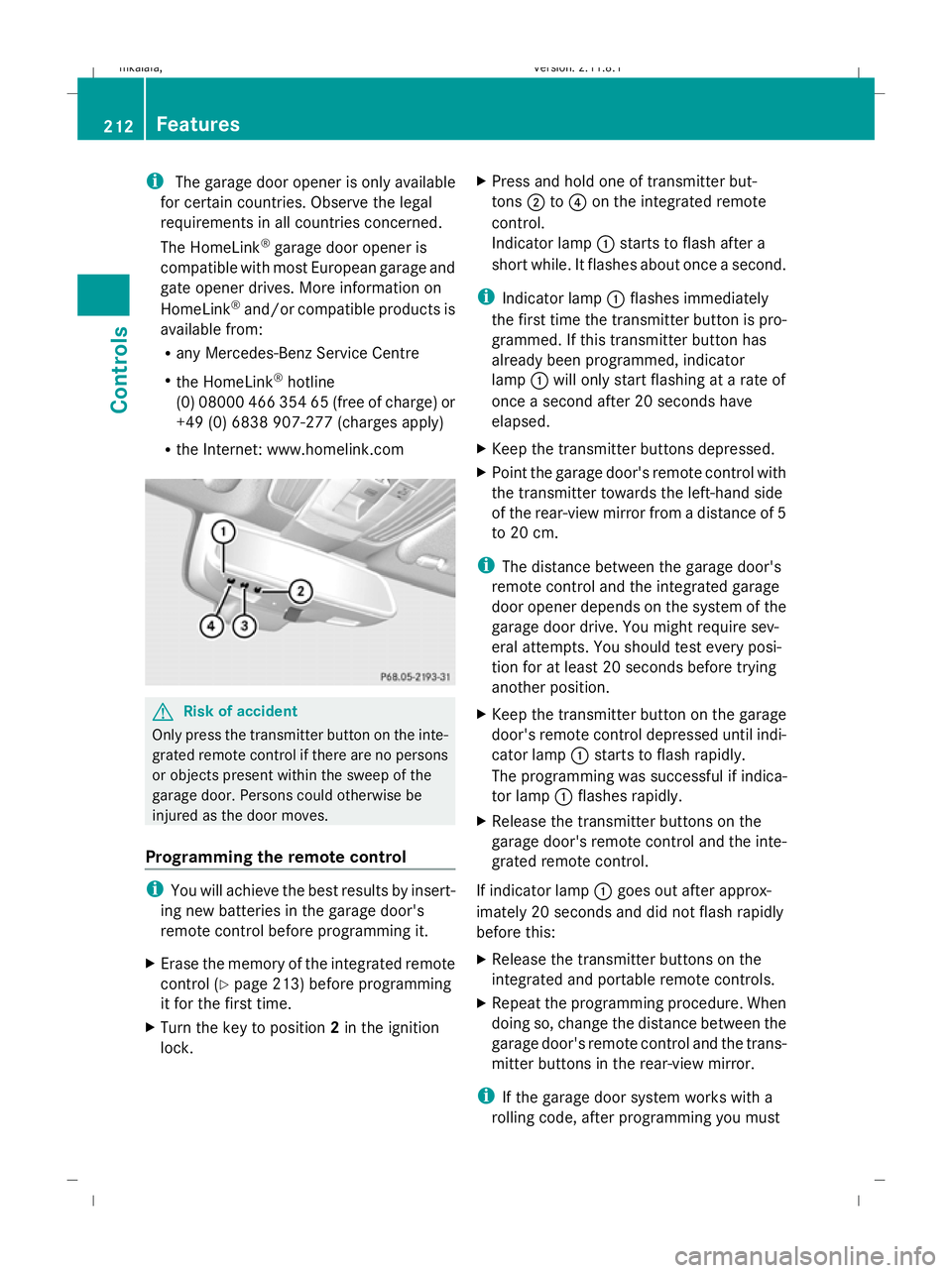
Programming the remote control i
You will achieve the best results by insert-
ing new batteries in the garage door's
remote control before programming it.
X Erase the memory of the integrated remote
control (Y page 213) before programming
it for the first time.
X Turn the key to position 2in the ignition
lock. X
Press and hold one of transmitter but-
tons ;to? on the integrated remote
control.
Indicator lamp :starts to flash after a
short while. It flashes about once a second.
i Indicator lamp :flashes immediately
the first time the transmitter button is pro-
grammed. If this transmitter button has
already been programmed, indicator
lamp :will only start flashing at a rate of
once a second after 20 seconds have
elapsed.
X Keep the transmitter buttons depressed.
X Point the garage door's remote control with
the transmitter towards the left-hand side
of the rear-view mirror from a distance of 5
to 20 cm.
i The distance between the garage door's
remote control and the integrated garage
door opener depends on the system of the
garage door drive. You might require sev-
eral attempts. You should test every posi-
tion for at least 20 seconds before trying
another position.
X Keep the transmitter button on the garage
door's remote control depressed until indi-
cator lamp :starts to flash rapidly.
The programming was successful if indica-
tor lamp :flashes rapidly.
X Release the transmitter buttons on the
garage door's remote control and the inte-
grated remote control.
If indicator lamp :goes out after approx-
imately 20 seconds and did not flash rapidly
before this:
X Release the transmitter buttons on the
integrated and portable remote controls.
X Repeat the programming procedure. When
doing so, change the distance between the
garage door's remote control and the trans-
mitter buttons in the rear-view mirror.
i If the garage door system works with a
rolling code, after programming you must 212
FeaturesControls
212_AKB; 2; 4, en-GB
mkalafa,
Version: 2.11.8.1 2009-05-05T14:17:16+02:00 - Seite 212
Dateiname: 6515346702_buchblock.pdf; erzeugt am 07. May 2009 14:16:52; WK
Page 216 of 373
synchronise the remote control integrated
in the rear-view mirror with the garage door
system receiver.
You will find further information in the
garage door opening system's operating
instructions, e.g. the sections on "Synchro-
nising the transmitter" or "Registering a
new transmitter". You can also call the hot-
line mentioned above.
Opening or closing the garage door Once programmed, the integrated remote
control will assume the function of the garage
door system's remote control. Please read
the operating instructions for the garage door
system.
X Turn the key to position 2in the ignition
lock.
X Press the transmitter button on the rear-
view mirror that you have programmed to
operate the garage door.
Garage door system with fixed code: indi-
cator lamp :lights up continuously.
Garage door system with rolling code: indi-
cator lamp :flashes briefly and then lights
up for approximately two seconds. This is
repeated for up to 20 seconds.
i The transmitter will transmit a signal for
as long as the transmitter button is being
pressed. The transmission will be halted
after a maximum of 20 seconds and indi-
cator lamp :will flash. Press the trans-
mitter button again, if necessary.
Clearing the remote control memory X
Turn the key to position 2in the ignition
lock.
X Press and hold transmitter buttons ;
and ?for approximately 20 seconds until
indicator lamp :flashes rapidly.
The memory is cleared.
i You should clear the remote control mem-
ory before selling the vehicle. Floormat* on the driver's side
G
Risk of accident
Make sure that there is sufficient clearance
around the pedals when floormats are used,
and that the floormats are properly secured.
The floormats must be correctly secured at all
times using retainers and press-studs.
Before you drive off, check the floormats and
secure if necessary. A floormat which is not
properly secured can slip and, thereby, inter-
fere with the movement of the pedals.
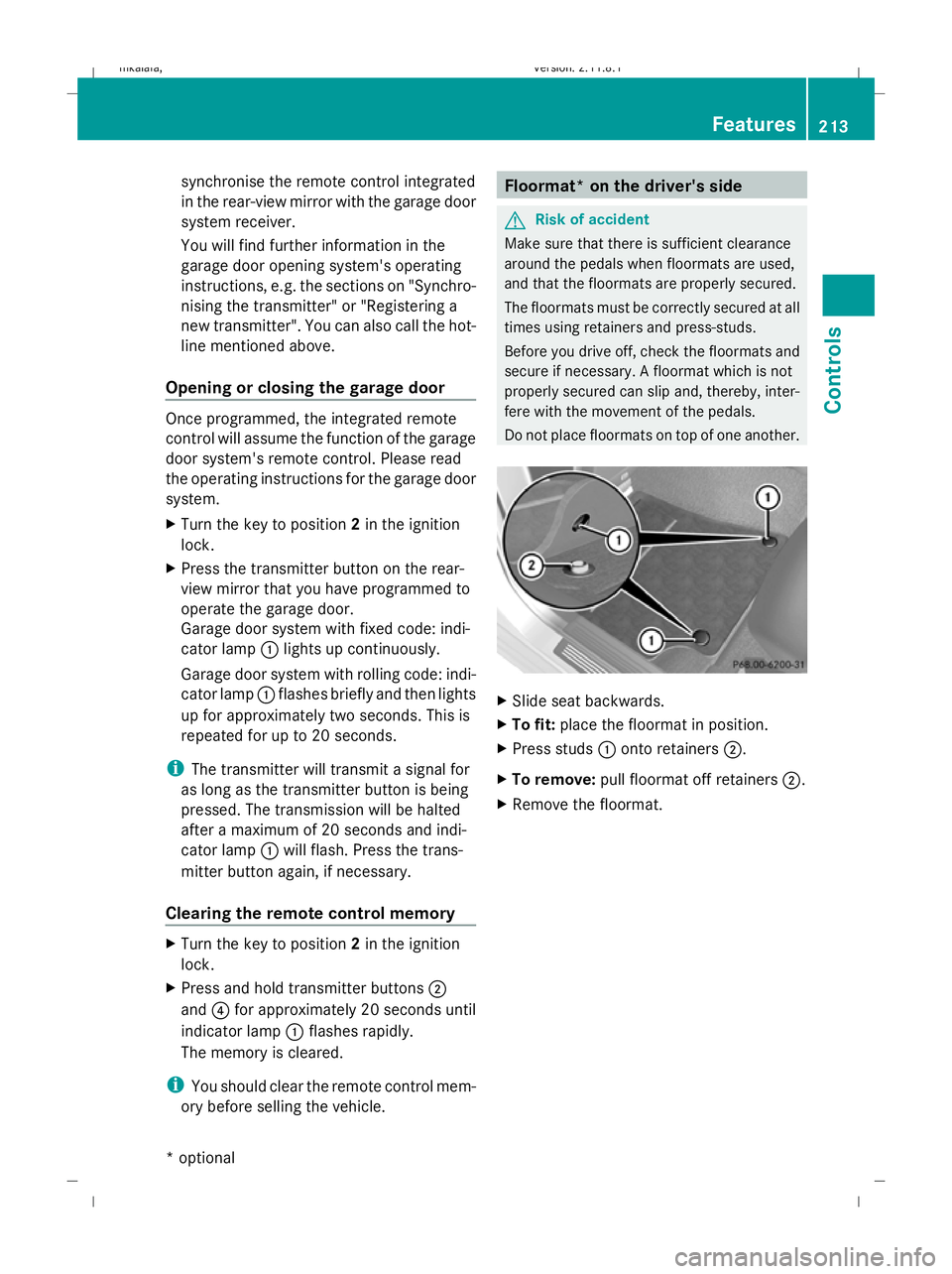
Do not place floormats on top of one another. X
Slide seat backwards.
X To fit: place the floormat in position.
X Press studs :onto retainers ;.
X To remove: pull floormat off retainers ;.
X Remove the floormat. Features
213Controls
* optional
212_AKB; 2; 4, en-GB
mkalafa,
Version: 2.11.8.1 2009-05-05T14:17:16+02:00 - Seite 213 Z
Dateiname: 6515346702_buchblock.pdf; erzeugt am 07. May 2009 14:16:52; WK
Page 255 of 373
outside temperature, warning and indicator
lamps, display messages or the failure of sys-
tems. The vehicle’s handling characteristics
may be affected. Adapt your driving style and
speed accordingly.
Immediately consult a qualified specialist
workshop which has the necessary specialist
knowledge and tools to carry out the work
required. Mercedes-Benz recommends that
you use a Mercedes-Benz Service Centre for
this purpose. In particular, work relevant to
safety or on safety-related systems must be
carried out at a qualified specialist workshop.
When you stop and park the vehicle, please
observe the instructions provided for HOLD
(Y page 151)and parking (Y page 107).
Calling up display messages The on-board computer saves certain display
messages, which you can call up.
X Press =or; on the steering wheel
to select the Servicemenu.
If there are display messages, the multi-
function display shows, e.g. 2 messages.
X Using 9or: select the entry, e.g.
2 messages. X
Confirm with a.
X Using :or9 scroll through the dis-
play messages.
Hiding display messages You cannot hide display messages of the
highest priority. The multi-function display
shows these messages continuously until
their causes have been remedied.
Use the buttons on the multi-function steer-
ing wheel.
X
Use the aor% button on the steer-
ing wheel to hide the display message.
The following tables contain all the display
messages. Text messages
G
Risk of accident and injury
The operating safety of the vehicle can be compromised if maintenance work is carried out
incorrectly. This could cause you to lose control of the vehicle and cause an accident. The safety
systems may also not be able to protect you or others as they are designed to do.
Always have maintenance work carried out at a qualified specialist workshop. The qualified spe-
cialist workshop must have the necessary specialist knowledge and tools to carry out the work
required. Mercedes-Benz recommends that you use a Mercedes-Benz Service Centre for this
purpose. In particular, work relevant to safety or on safety-related systems must be carried out
at a qualified specialist workshop. 252
Display messagesPractical advice
212_AKB; 2; 4, en-GB
mkalafa,
Version: 2.11.8.1 2009-05-05T14:17:16+02:00 - Seite 252
Dateiname: 6515346702_buchblock.pdf; erzeugt am 07. May 2009 14:17:07; WK