2009 KIA SOUL audio
[x] Cancel search: audioPage 157 of 328
485
Features of your vehicle
8. TUNE Knob & Sound QualityControl Knob
Rotate the knob clockwise by one notch
to increase frequency by 50kHz from cur-
rent frequency.
Rotate the knob counterclockwise by one
notch to decrease frequency by 50kHz
from current frequency.
MIDDLE, TREBLE, FADER and BAL-
ANCE TUNE mode. The mode selected
is shown on the display. After selecting
each mode, rotate the Audio control
knob clockwise or counterclockwise.
(Sound Quality Control will operate in
FM, MW, LW, CD, AUX, USB and iPod
modes.)
To increase the BASS, rotate the knob
clockwise, while to decrease the BASS,
rotate the knob counterclockwise.
To increase the MIDDLE, rotate the knob
clockwise, while to decrease the MID-
DLE, rotate the knob counterclockwise. Control
To increase the TREBLE, rotate the knob
clockwise, while to decrease the TRE-
BLE, rotate the knob counterclockwise.
Turn the control knob clockwise to empha-
size rear speaker sound(front speaker
sound will be attenuated). When the con-
trol knob is turned counterclockwise, front
speaker sound will be emphasized(rear
speaker sound will be attenuated).
Rotate the knob clockwise to emphasize
right speaker sound(left speaker sound
will be attenuated). When the control
knob is turned counter clockwise, left
speaker sound will be emphasized(right
speaker sound will be attenuated).
9. PTY(FOLDER) Button
Press [PTY ] button when searching
PTY in RDS Broadcasting Program
Type selection.
Press [PTY ] button when searching PTY in RDS Broadcasting Program
Type selection. 10. Preset Button
Push [1]~[6] buttons less than 0.8 second
to play the channel saved in each button.
Push Preset button for 0.8 second or
longer to save current channel to the
respective button with a beep.
Page 160 of 328
Features of your vehicle
88
4
8. TUNE Knob & Sound Quality
Control Knob
Rotate the knob clockwise by one notch
to increase frequency by 200kHz from
current frequency.
Rotate the knob counterclockwise by one
notch to decrease frequency by 200kHz
from current frequency.
MIDDLE, TREBLE, FADER and BAL-
ANCE TUNE mode. The mode selected
is shown on the display. After selecting
each mode, rotate the Audio control
knob clockwise or counterclockwise.
(Sound Quality Control will operate in FM,
AM, CD, AUX, USB, and iPod modes.)
To increase the BASS, rotate the knob
clockwise, while to decrease the BASS,
rotate the knob counterclockwise.
To increase the MIDDLE, rotate the knob
clockwise, while to decrease the MID-
DLE, rotate the knob counterclockwise. Control
To increase the TREBLE, rotate the knob
clockwise, while to decrease the TRE-
BLE, rotate the knob counterclockwise.
Turn the control knob clockwise to
emphasize rear speaker sound(front
speaker sound will be attenuated). When
the control knob is turned counterclock-
wise, front speaker sound will be empha-
sized(rear speaker sound will be attenu-ated).
Rotate the knob clockwise to emphasize
right speaker sound(left speaker sound
will be attenuated). When the control
knob is turned counter clockwise, left
speaker sound will be emphasized(right
speaker sound will be attenuated).
9. Preset Button
Push [1]~[6] buttons less than 0.8 second
to play the channel saved in each button.
Push Preset button for 0.8 second or
longer to save current channel to the
respective button with a beep.
Page 167 of 328
495
Features of your vehicle
(Continued) If you use devices such as a USB hub you purchased separately,the vehicle’s audio system may
not recognize the USB device.Connect the USB device directlyto the multimedia terminal of the
vehicle.
If the USB device is divided by logical drives, only the music fileson the highest-priority drive are
recognized by the vehicle’s audio.
Devices such as MP3 Player/ Cellular phone/Digital camera,those are not recognizable bystandard USB I/F (IMPLE-
MENTERS FORUM) can be unrec-ognizable.
USB devices other than standard- ized goods (METAL COVER TYPEUSB) can be unrecognizable.
USB flash memory reader (such as CF, SD, microSD, etc.) or exter-nal-HDD type devices can beunrecognizable.
Music files protected by DRM(DIGITAL RIGHTS MANAGE-MENT) are not recognizalbe.
(Continued)(Continued) The data in the USB memory may get lost while using this AUDIO. Itis recommeded to back up impor-tant data.
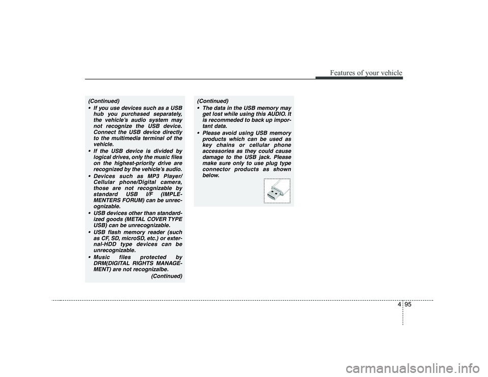
Please avoid using USB memory products which can be used as
key chains or cellular phone accessories as they could causedamage to the USB jack. Please
make sure only to use plug typeconnector products as shown below.
Page 281 of 328
Maintenance
40
7
G190300AUN-SA Reset items
Items should be reset after the battery
has been discharged or the battery hasbeen disconnected.
Sunroof (See section 4)
Climate control system
(See section 4)
Clock (See section 4, Audio)
Audio (See section 4)
WARNING
Before performing maintenance or recharging the battery, turn off all accessories and stop the
engine.
The negative battery cable must be removed first and installed
last when the battery is discon-nected.
Page 297 of 328
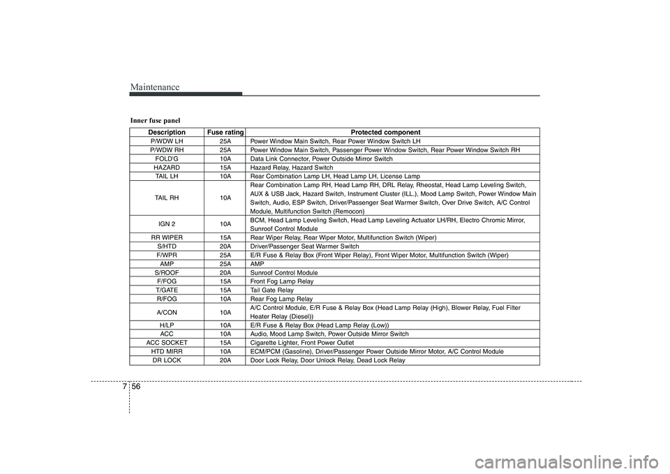
Maintenance
56
7
Inner fuse panel
Description Fuse rating Protected component
P/WDW LH 25A Power Window Main Switch, Rear Power Window Switch LH
P/WDW RH 25A Power Window Main Switch, Passenger Power Window Switch, Rear Power Window Switch RH FOLD'G 10A Data Link Connector, Power Outside Mirror Switch
HAZARD 15A Hazard Relay, Hazard Switch TAIL LH 10A Rear Combination Lamp LH, Head Lamp LH, License Lamp
TAIL RH 10A Rear Combination Lamp RH, Head Lamp RH, DRL Relay, Rheostat, Head Lamp Leveling Switch,
AUX & USB Jack, Hazard Switch, Instrument Cluster (ILL.), Mood Lamp Switch, Power Window Main
Switch, Audio, ESP Switch, Driver/Passenger Seat Warmer Switch, Over Drive Switch, A/C Control
Module, Multifunction Switch (Remocon)
IGN 2 10A BCM, Head Lamp Leveling Switch, Head Lamp Leveling Actuator LH/RH, Electro Chromic Mirror,Sunroof Control Module
RR WIPER 15A Rear Wiper Relay, Rear Wiper Motor, Multifunction Switch (Wiper) S/HTD 20A Driver/Passenger Seat Warmer Switch
F/WPR 25A E/R Fuse & Relay Box (Front Wiper Relay), Front Wiper Motor, Multifunction Switch (Wiper) AMP 25A AMP
S/ROOF 20A Sunroof Control Module F/FOG 15A Front Fog Lamp Relay
T/GATE 15A Tail Gate Relay R/FOG 10A Rear Fog Lamp Relay
A/CON 10A A/C Control Module, E/R Fuse & Relay Box (Head Lamp Relay (High), Blower Relay, Fuel Filter
Heater Relay (Diesel))
H/LP 10A E/R Fuse & Relay Box (Head Lamp Relay (Low)) ACC 10A Audio, Mood Lamp Switch, Power Outside Mirror Switch
ACC SOCKET 15A Cigarette Lighter, Front Power Outlet HTD MIRR 10A ECM/PCM (Gasoline), Driver/Passenger Power Outside Mirror Motor, A/C Control ModuleDR LOCK 20A Door Lock Relay, Door Unlock Relay, Dead Lock Relay
Page 298 of 328
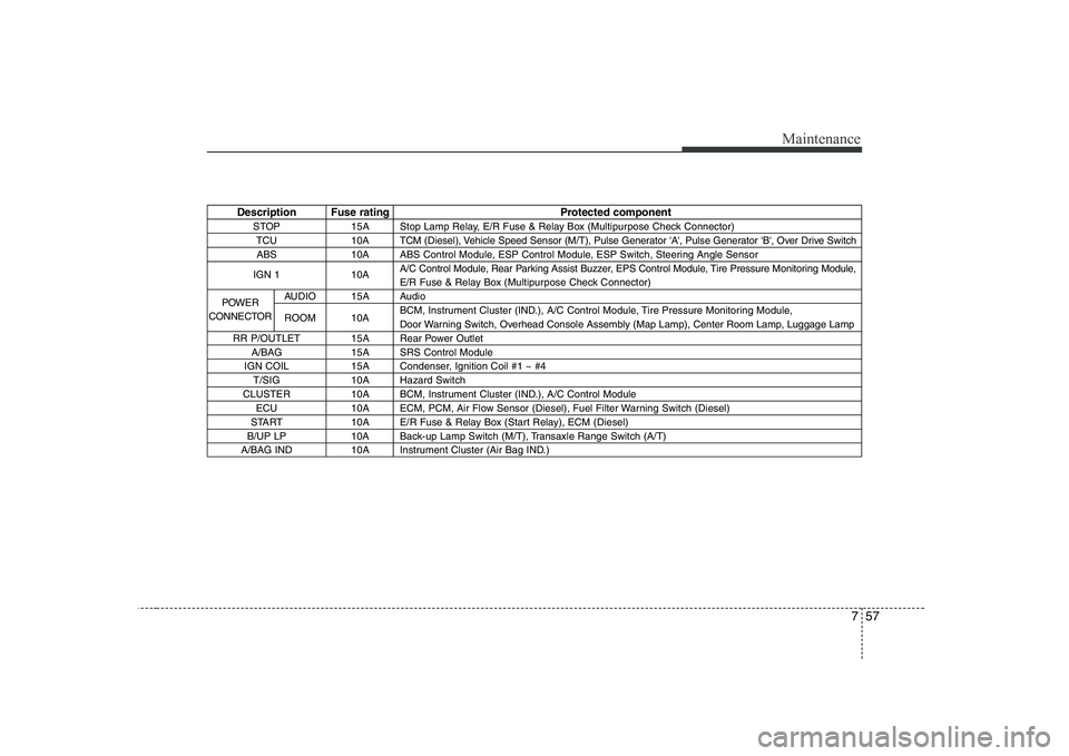
757
Maintenance
Description Fuse rating Protected componentSTOP 15A Stop Lamp Relay, E/R Fuse & Relay Box (Multipurpose Check Connector)TCU 10A TCM (Diesel), Vehicle Speed Sensor (M/T), Pulse Generator 'A', Pulse Generator 'B', Over Drive SwitchABS 10A ABS Control Module, ESP Control Module, ESP Switch, Steering Angle Sensor
IGN 1 10A A/C Control Module, Rear Parking Assist Buzzer, EPS Control Module, Tire Pressure Monitoring Module,
E/R Fuse & Relay Box (Multipurpose Check Connector)
AUDIO 15A Audio
ROOM 10A BCM, Instrument Cluster (IND.), A/C Control Module, Tire Pressure Monitoring Module,
Door Warning Switch, Overhead Console Assembly (Map Lamp), Center Room Lamp, Luggage Lamp
RR P/OUTLET 15A Rear Power Outlet A/BAG 15A SRS Control Module
IGN COIL 15A Condenser, Ignition Coil #1 ~ #4 T/SIG 10A Hazard Switch
CLUSTER 10A BCM, Instrument Cluster (IND.), A/C Control Module ECU 10A ECM, PCM, Air Flow Sensor (Diesel), Fuel Filter Warning Switch (Diesel)
START 10A E/R Fuse & Relay Box (Start Relay), ECM (Diesel)
B/UP LP 10A Back-up Lamp Switch (M/T), Transaxle Range Switch (A/T)
A/BAG IND 10A Instrument Cluster (Air Bag IND.)
POWER
CONNECTOR
Page 299 of 328
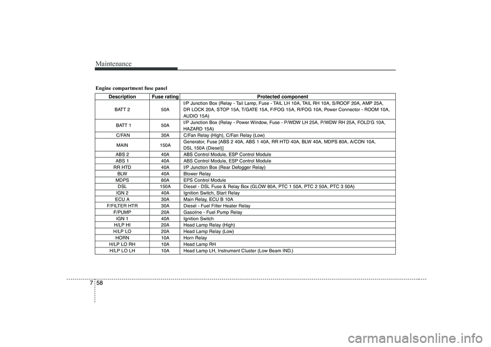
Maintenance
58
7
Engine compartment fuse panel
Description Fuse rating Protected component
BATT 2 50A I/P Junction Box (Relay - Tail Lamp, Fuse - TAIL LH 10A, TAIL RH 10A, S/ROOF 20A, AMP 25A,
DR LOCK 20A, STOP 15A, T/GATE 15A, F/FOG 15A, R/FOG 10A, Power Connector - ROOM 10A,
AUDIO 15A)
BATT 1 50A I/P Junction Box (Relay - Power Window, Fuse - P/WDW LH 25A, P/WDW RH 25A, FOLD'G 10A,HAZARD 15A)
C/FAN 30A C/Fan Relay (High), C/Fan Relay (Low)
MAIN 150A Generator, Fuse [ABS 2 40A, ABS 1 40A, RR HTD 40A, BLW 40A, MDPS 80A, A/CON 10A, DSL 150A (Diesel)]
ABS 2 40A ABS Control Module, ESP Control Module
ABS 1 40A ABS Control Module, ESP Control Module
RR HTD 40A I/P Junction Box (Rear Defogger Relay) BLW 40A Blower Relay
MDPS 80A EPS Control Module DSL 150A Diesel - DSL Fuse & Relay Box (GLOW 80A, PTC 1 50A, PTC 2 50A, PTC 3 50A)
IGN 2 40A Ignition Switch, Start Relay
ECU A 30A Main Relay, ECU B 10A
F/FILTER HTR 30A Diesel - Fuel Filter Heater Relay F/PUMP 20A Gasoline - Fuel Pump RelayIGN 1 40A Ignition Switch
H/LP HI 20A Head Lamp Relay (High)
H/LP LO 20A Head Lamp Relay (Low) HORN 10A Horn Relay
H/LP LO RH 10A Head Lamp RH H/LP LO LH 10A Head Lamp LH, Instrument Cluster (Low Beam IND.)
Page 326 of 328
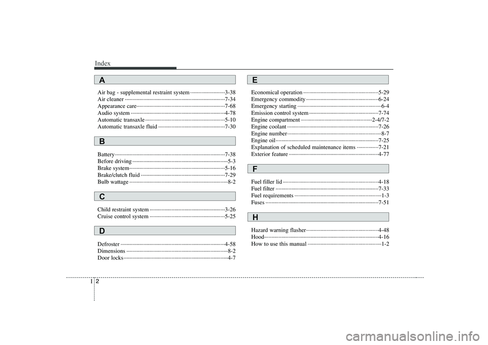
Index
2
I
Air bag - supplemental restraint system ························3-38
Air cleaner ·····································································7-34
Appearance care·····························································7-68
Audio system ·································································4-78
Automatic transaxle ·······················································5-10
Automatic transaxle fluid ··············································7-30
Battery············································································7-38
Before driving ··································································5-3
Brake system··································································5-16
Brake/clutch fluid ··························································7-29
Bulb wattage ····································································8-2
Child restraint system ····················································3-26
Cruise control system ····················································5-25
Defroster ········································································4-58
Dimensions ······································································8-2
Door locks········································································4-7 Economical operation ····················································5-29
Emergency commodity ··················································6-24
Emergency starting ··························································6-4
Emission control system ················································7-74
Engine compartment ·················································2-4/7-2
Engine coolant ·······························································7-26
Engine number ·································································8-7
Engine oil ·······································································7-25
Explanation of scheduled maintenance items ···············7-21
Exterior feature ······························································4-77
Fuel filler lid ··································································4-18
Fuel filter ·······································································7-33
Fuel requirements ····························································1-3
Fuses ··············································································7-51
Hazard warning flasher··················································4-48
Hood···············································································4-16
How to use this manual ···················································1-2
A
B
C
D
E
F
H