Page 317 of 502
If necessary, add fluid to restore to the proper indicated
level. With a clean cloth, wipe any spilled fluid from all
surfaces. Refer to “Fluids, Lubricants, and Genuine
Parts” in Section 7 for the correct fluid type.
PARKING BRAKE
NOTE:This vehicle is not equipped with a self-
adjusting parking brake system. Refer to the “Mainte-
nance Schedule” in Section 8 for the proper maintenance
intervals.
To set the parking brake, pull the lever up as firmly as
possible. When the parking brake is applied with the
ignition ON, the “Brake Warning Light” in the instru-
ment cluster will light. To release the parking brake, pull
up slightly, press the center button, then lower the lever
completely. NOTE:
The instrument cluster “Brake Warning Light”
indicates only that the parking brake is applied. You must
be sure the parking brake is fully applied before leaving
the vehicle.
Parking Brake
5
STARTING AND OPERATING 315
Page 352 of 502

TIRE CHAINS
Install chains on rear tires only. Tire chains may be
installed on all models except the Sahara and Rubicon.
Follow these recommendations to guard against damage
and excessive tire and chain wear:
•Use chains on P225/75R16 tires only. P255/75R17,
P255/70R18, and LT255/75R17 tires do not provide
adequate clearance.
•Use SAE class “S” tire chains or traction devices only.
•Chains must be the proper size for the vehicle, as
recommended by the chain manufacturer.
•Follow tire chain manufacturer’s instructions for
mounting chains.
•Install chains snugly and tighten after 0.6 mile (1 km)
of driving.
•Do notexceed 30 mph (48 km/h).
•Drive cautiously, avoiding large bumps, potholes and
extreme driving maneuvers.
TIRE ROTATION RECOMMENDATIONS
Tires on the front and rear axles of vehicles operate at
different loads and perform different steering, handling,
and braking functions. For these reasons, they wear at
unequal rates, and develop irregular wear patterns.
These effects can be reduced by timely rotation of tires.
The benefits of rotation are especially worthwhile with
aggressive tread designs such as those on On/Off Road
type tires. Rotation will increase tread life, help to main-
tain mud, snow, and wet traction levels, and contribute to
a smooth, quiet ride.
Refer to the “Maintenance Schedule” in Section 8 for the
proper maintenance intervals. More frequent rotation is
permissible if desired. The reasons for any rapid or
unusual wear should be corrected prior to rotation being
performed.
350 STARTING AND OPERATING
Page 355 of 502

CAUTION! (Continued)
•After inspecting or adjusting the tire pressure,
always reinstall the valve stem cap. This will
prevent moisture and dirt from entering the valve
stem, which could damage the Tire Pressure Moni-
toring Sensor.
NOTE:
•The TPMS is not intended to replace normal tire care
and maintenance, nor to provide warning of a tire
failure or condition.
•The TPMS should not be used as a tire pressure gauge
while adjusting your tire pressure.
•Driving on a significantly under-inflated tire causes
the tire to overheat and can lead to tire failure.
Under-inflation also reduces fuel efficiency and tire
tread life, and may affect the vehicle’s handling and
stopping ability.
•The TPMS is not a substitute for proper tire mainte-
nance, and it is the driver ’s responsibility to maintain
correct tire pressure, even if under-inflation has not
reached the level to trigger illumination of the “Tire
Pressure Monitoring Telltale Light.”
•Seasonal temperature changes will affect tire pressure,
and the TPMS will monitor the actual tire pressure in
the tire.
Base System
The Tire Pressure Monitor System (TPMS) uses wireless
technology with wheel rim-mounted electronic sensors to
monitor tire pressure levels. Sensors, mounted to each
wheel as part of the valve stem, transmit tire pressure
readings to the Receiver Module.
NOTE: It is particularly important for you to check the
tire pressure in all of your tires regularly and to maintain
the proper pressure.
5
STARTING AND OPERATING 353
Page 363 of 502
WARNING! (Continued)
•Guard against carbon monoxide with proper
maintenance. Have the exhaust system inspected
every time the vehicle is raised. Have any abnor-
mal conditions repaired promptly. Until repaired,
drive with all side windows fully open.
•Keep the swing gate closed when driving your
vehicle to prevent carbon monoxide and other
poisonous exhaust gases from entering the vehicle.
ADDING FUEL
Fuel Filler Cap (Gas Cap)
The gas cap is located on the driver’s side of the vehicle.
If the gas cap is lost or damaged, be sure the replacement
cap is the correct one for this vehicle.
Fuel Filler Cap
5
STARTING AND OPERATING 361
Page 401 of 502
MAINTAINING YOUR VEHICLE
CONTENTS
�Engine Compartment – 3.8L .............. 401
� Onboard Diagnostic System — OBD II ...... 402
▫ Loose Fuel Filler Cap Message ........... 402
� Emissions Inspection And Maintenance
Programs ............................ 403
� Replacement Parts ..................... 404
� Dealer Service ........................ 405
� Maintenance Procedures ................. 405
▫ Engine Oil ......................... 406 ▫
Engine Oil Filter ..................... 408
▫ Engine Air Cleaner Filter ............... 409
▫ Maintenance-Free Battery .............. 409
▫ Air Conditioner Maintenance ............ 410
▫ Body Lubrication .................... 411
▫ Windshield Wiper Blades ............... 412
▫ Adding Washer Fluid ................. 412
▫ Exhaust System ..................... 413
▫ Cooling System ..................... 416
7
Page 402 of 502

▫Brake System ....................... 421
▫ Automatic Transmission — If Equipped .... 423
▫ Hydraulic Clutch Fluid — Manual
Transmission ....................... 426
▫ Manual Transmission — If Equipped ...... 426
▫ Transfer Case — If Equipped ............ 426
▫ Front/Rear Axle Fluid ................. 427
▫ Maintenance After Off-Road Driving ...... 428
▫ Appearance Care And Protection From
Corrosion .......................... 428
� Fuses .............................. 436
▫ Totally Integrated Power Module ......... 436
� Vehicle Storage ....................... 442
� Replacement Bulbs .................... 443 �
Bulb Replacement ..................... 444
▫ Headlamp ......................... 444
▫ Front Park/Turn Signal ................ 445
▫ Front Side Marker .................... 445
▫ Front Fog Lamp ..................... 445
▫ Rear Tail, Stop, Turn Signal, And Backup
Lamp ............................. 446
▫ Center High-Mounted Stop Lamp
(CHMSL) .......................... 446
� Fluid Capacities ...................... 447
� Fluids, Lubricants And Genuine Parts ....... 448
▫ Engine ............................ 448
▫ Chassis ........................... 449
400 MAINTAINING YOUR VEHICLE
Page 405 of 502

the message will appear the next time the vehicle is
started. This might indicate a damaged cap. If the prob-
lem is detected twice in a row, the system will turn on the
MIL. Resolving the problem will turn the MIL off.
EMISSIONS INSPECTION AND MAINTENANCE
PROGRAMS
In some localities, it may be a legal requirement to pass
an inspection of your vehicle’s emissions control system.
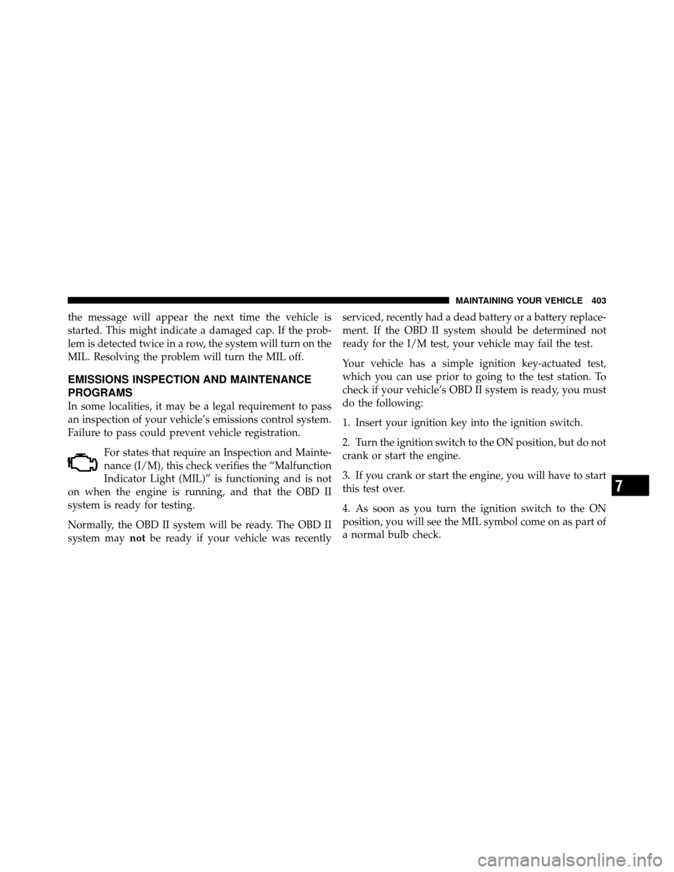
Failure to pass could prevent vehicle registration.For states that require an Inspection and Mainte-
nance (I/M), this check verifies the “Malfunction
Indicator Light (MIL)” is functioning and is not
on when the engine is running, and that the OBD II
system is ready for testing.
Normally, the OBD II system will be ready. The OBD II
system may notbe ready if your vehicle was recently serviced, recently had a dead battery or a battery replace-
ment. If the OBD II system should be determined not
ready for the I/M test, your vehicle may fail the test.
Your vehicle has a simple ignition key-actuated test,
which you can use prior to going to the test station. To
check if your vehicle’s OBD II system is ready, you must
do the following:
1. Insert your ignition key into the ignition switch.
2. Turn the ignition switch to the ON position, but do not
crank or start the engine.
3. If you crank or start the engine, you will have to start
this test over.
4. As soon as you turn the ignition switch to the ON
position, you will see the MIL symbol come on as part of
a normal bulb check.
7
MAINTAINING YOUR VEHICLE 403
Page 406 of 502

5. Approximately 15 seconds later, one of two things will
happen:a. The MIL will flash for about 10 seconds and then
return to being fully illuminated until you turn OFF
the ignition or start the engine. This means that your
vehicle’s OBD II system is not readyand you should
not proceed to the I/M station.
b. The MIL will not flash at all and will remain fully
illuminated until you turn OFF the ignition or start the
engine. This means that your vehicle’s OBD II system
is ready and you can proceed to the I/M station.
If your OBD II system is not ready,you should see your
authorized dealer or repair facility. If your vehicle was
recently serviced or had a battery failure or replacement,
you may need to do nothing more than drive your
vehicle as you normally would in order for your OBD II
system to update. A recheck with the above test routine
may then indicate that the system is now ready. Regardless of whether your vehicle’s OBD II system is
ready or not, if the MIL is illuminated during normal
vehicle operation you should have your vehicle serviced
before going to the I/M station. The I/M station can fail
your vehicle because the MIL is on with the engine
running.
REPLACEMENT PARTS
Use of genuine MOPAR�
parts for normal/scheduled
maintenance and repairs is highly recommended to en-
sure the designed performance. Damage or failures
caused by the use of non-MOPAR� parts for maintenance
and repairs will not be covered by the manufacturer’s
warranty.
404 MAINTAINING YOUR VEHICLE