2009 JAGUAR XF Warning
[x] Cancel search: WarningPage 105 of 391

105
Information displays
GENERAL INFORMATION
The driver message centre display is situated
within the instrument panel between the
tachometer and speedometer gauges. The
message centre is active as soon as a door is
opened for access.
The primary function of the message centre is
to inform the driver of the following:
• Warning messages.
• Temporary alert messages.
• Information messages.
• Turn-by-turn navigation.
The message centre screen is divided into
various zones displaying the following:
1. Gear selection, automatic or manual.
2. Warning messages, accompanied by a red
or amber backlight, if system faults are
detected. Status messages are displayed
to indicate changes in state of certain
vehicle functions (e.g. navigation). When there are no current warning
messages, turn-by-turn navigation
information is displayed, giving
instructions for the next junction. This
facility can be turned off via the
touch-screen. See
TURN-BY-TURN
NAVIGATION (page 339).
The clock can be shown when no other
information is required to be displayed.
See CLOCK (page 124).
3. Trip computer information, including total
distance covered by the vehicle. See TRIP
COMPUTER (page 107).
4. Set trip computer information display
relating A, B or Auto trip computer.
See PERSONALISED SETTINGS
(page 111).
On diesel and V8 petrol models, the
electronic engine oil dipstick reading can
also be displayed, when selected using the
trip computer button. See ENGINE OIL
CHECK - V8 Petrol engines (page 199).
5. The fuel level gauge. The small arrow on
the top of the fuel pump symbol denotes
which side of the vehi cle the fuel filler cap
is located.
Automiles
Inst Fuelmpg
BOOT OPEN
E95066
1
2
3
4
5
Page 106 of 391

Information displays
106
WARNING AND INFORMATION
MESSAGES
Most displayed warning messages have an
associated warning indicator, which will
illuminate on to indicate the message priority.
Also from time to time information messages
will be displayed.
If more than one message is active, each is
displayed in turn for two seconds in order of
priority.
Messages take priority over the trip computer
data and will be displayed when the ignition is
on.
Note: The message centre information
messages and their meanings, are detailed
where necessary within the appropriate subject
sections.
Clearing messages from the display
It is possible to temporarily clear certain
warning or information messages from the
message centre.
When a message is displayed in the message
centre (e.g. WASHER FLUID LOW ), a red
warning triangle icon appears on the
touch-screen, where shown.
Touch the icon to temporarily stop the
currently displayed message from appearing.
Once the message is removed, the colour of
the warning icon in the message centre
changes to white, as a reminder that an
outstanding message exists.
Note: Certain warnings, that are critical for the
safe operation of the vehi cle, cannot be cleared
from the display.
Note: If multiple messages are displayed, this
process can be repeated to remove all
messages from the display.
Removed messages will display again,
whenever the ignition is switched on, until the
fault is rectified (i.e. in this example, when the
washer fluid is topped up).
WARNING
If a warning indicato r is displayed,
stop the vehicle as soon as possible
when it is safe to do so. Do not ignore
critical warning messages. Failure to do so
may result in serious damage to the vehicle.
Home
Audio/TV
Climate
Phone
Navigation
Vehicle
Valet12:26 pm
External15C
Left Right
20 17CC.5 .5DAB radio DAB1BBC 5Live Xtra
BBC National DAB
TA FM DAB i Subch.
JAG1515
Page 108 of 391

Information displays
108
Average fuel consumption (A, B and
Auto)
The average fuel consumption, stated as litres
per 100 kilometres (except Japan, kilometres
per litre), miles per litre or miles per gallon (UK
only), based on the accumulated distance
travelled and the accumulated fuel used.
Range
This shows the predicte d distance, miles or
kilometres, that the vehi cle should travel on the
remaining fuel, assuming average fuel
economy and fuel consum ption stay constant.
Electronic dipstick (diesel and V8 petrol
engines only)
This shows the current engine oil level and any
associated warnings. SeeENGINE OIL CHECK -
V8 Petrol engines (page 199).
ML-km (also Miles-litre)
The display of metric or imperial units is
selected via the touch-screen.
Display language
The display language is selected via the
touch-screen.
Reset
Resetting of the trip memo ries is carried out via
the touch-screen.
Service interval indicator
The service interval message will only be
displayed when the vehicle has less than
3400 km (2000 miles) before the service is
due.
When the ignition is switched on, and the
vehicle has started it s service countdown,
SERVICE REQ'D XXXX km (XXXX MLS) is
displayed in the message centre. At the same
time the display will glow Amber.
After approximat ely five seconds, the display
reverts to show the preset requirements.
When the service distance has been reached,
SERVICE REQUIRED is displayed in the
message centre and the display will glow Red.
After approximat ely five seconds, the display
reverts to show the preset requirements.
The distance countdown re duces in increments
of 50 km or 50 miles, depending on which
display units have been selected.
The distance countdown is controlled by the
engine management system and is
automatically adjusted to allow for driving style
and conditions. This ga uges when the service
becomes necessary.
Note: After the completion of each service, the
Dealer/Authorised Repairer will reset the
distance display to commence the countdown
to the next service.
CAUTION
If no service interv al indicator is
displayed during the vehicle service
cycle, make sure that your vehicle is serviced
in accordance with the intervals, as stated in
the Service Portfolio.
Page 110 of 391

Information displays
110
Touch-screen use
When the engine START/STOP button is
pressed, the touch-screen is activated by the
on/off switch on the centre console.
The buttons on the centre console, below the
touch-screen display, are referred to as hard
buttons and should be pressed firmly. The
touch-screen buttons are soft buttons and only
require short, light pressu re to function. Do not
use excessive pressure.
When operating touch-sc reen buttons, always
extend the tip of one finger, and withhold the
thumb and remaining finge rs from the screen.
Touching the screen with more than one finger
at a time may cause false inputs.
Throughout the handbook, the expression
Select an item (or similar wording) means
touch the on-screen button to select or alter
the required item.
The handbook shows the on-screen menus,
explains how to oper ate the controls and
illustrates how to select or alter settings and
requirements. After becoming familiar with the
controls, follow the on-screen menus and
prompts, to operate th e system as required.
Touch-screen display icons
Touch-screen display icons are as follows
(they may not all be displayed at the same
time):WARNING
In the interest of road safety, only
operate, adjust or view the system
when it is safe to do so.
CAUTION
Always run the engine during prolonged
use of the touch-screen. Failure to do so
may discharge the vehicle battery, preventing
the engine from starting.
Return to the previous screen
displayed.
Warning triangle button indicating
an information or warning
message in the message centre.
Touch the button to temporarily remove the
warning message from the message centre
display. See WARNING AND INFORMATION
MESSAGES (page 106).
Telephone: send button.
Telephone: end call.
Page up or increase setting to
required value.
Page down or decrease setting to
required value.
Direct access to the valet mode
setting screen.
Telephone signal strength
indicator (if supported by
Bluetooth phone).
Telephone battery level indicator
(if supported by Bluetooth phone).
No phone connected.
Valet
Page 121 of 391

121
Climate control
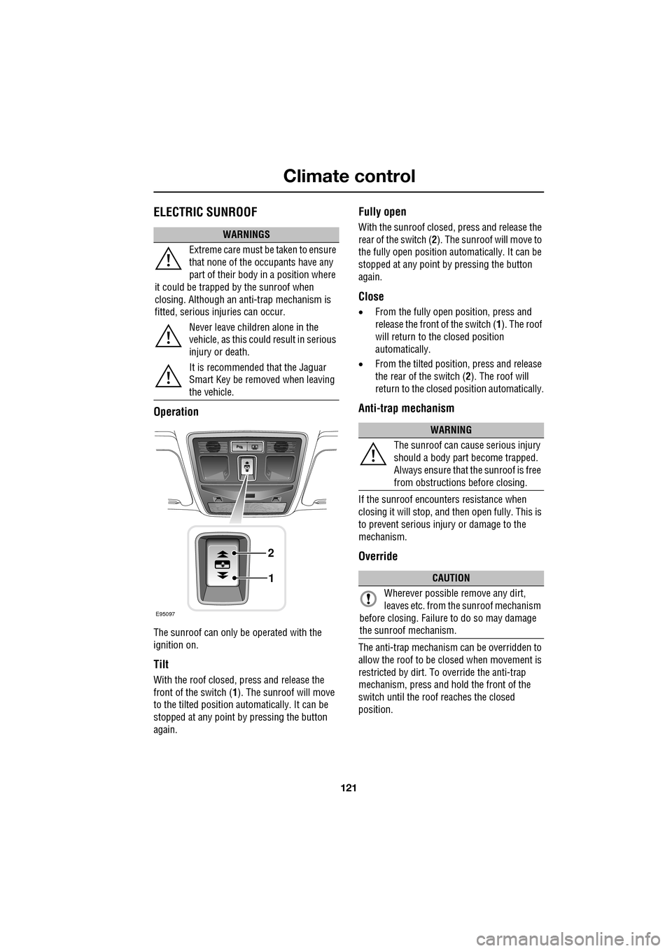
ELECTRIC SUNROOF
Operation
The sunroof can only be operated with the
ignition on.
Tilt
With the roof closed, press and release the
front of the switch (1). The sunroof will move
to the tilted position automatically. It can be
stopped at any point by pressing the button
again.
Fully open
With the sunroof closed, press and release the
rear of the switch ( 2). The sunroof will move to
the fully open position auto matically. It can be
stopped at any point by pressing the button
again.
Close
• From the fully open position, press and
release the front of the switch ( 1). The roof
will return to the closed position
automatically.
• From the tilted position, press and release
the rear of the switch ( 2). The roof will
return to the closed position automatically.
Anti-trap mechanism
If the sunroof encounters resistance when
closing it will stop, and then open fully. This is
to prevent serious injury or damage to the
mechanism.
Override
The anti-trap mechanism can be overridden to
allow the roof to be closed when movement is
restricted by dirt. To override the anti-trap
mechanism, press and hold the front of the
switch until the roof reaches the closed
position.
WARNINGS
Extreme care must be taken to ensure
that none of the oc cupants have any
part of their body in a position where
it could be trapped by the sunroof when
closing. Although an anti-trap mechanism is
fitted, serious injuries can occur.
Never leave children alone in the
vehicle, as this could result in serious
injury or death.
It is recommended that the Jaguar
Smart Key be removed when leaving
the vehicle.
E95097
1
2
WARNING
The sunroof can cause serious injury
should a body part become trapped.
Always ensure that the sunroof is free
from obstructions before closing.
CAUTION
Wherever possible remove any dirt,
leaves etc. from the sunroof mechanism
before closing. Failure to do so may damage
the sunroof mechanism.
Page 126 of 391

Convenience features
126
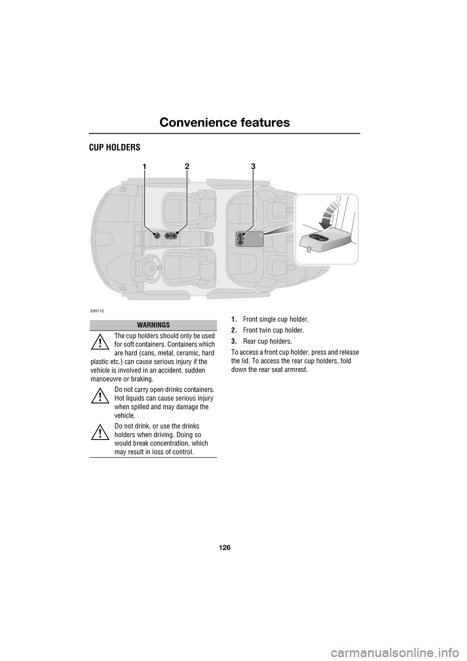
CUP HOLDERS
1.Front single cup holder.
2. Front twin cup holder.
3. Rear cup holders.
To access a front cup holder, press and release
the lid. To access the re ar cup holders, fold
down the rear seat armrest.
E95112
123
WARNINGS
The cup holders shoul d only be used
for soft containers . Containers which
are hard (cans, metal, ceramic, hard
plastic etc.) can cause serious injury if the
vehicle is involved in an accident, sudden
manoeuvre or braking.
Do not carry open drinks containers.
Hot liquids can cause serious injury
when spilled and may damage the
vehicle.
Do not drink, or use the drinks
holders when driving. Doing so
would break concentration, which
may result in loss of control.
Page 127 of 391

127
Convenience features
Twin cup holder
The twin cup holder can be converted into a
storage compartment by removing the insert.
Use one hand to squeeze the two sides of the
insert together and, lifting the edge nearest the
driver first, use the other hand to rotate the
insert up and out of it s compartment, towards
the passenger seat.
Note: An ashtray and cigar lighter pack, which
replaces the front twin cup holder, is available
from your Dealer/A uthorised Repairer.
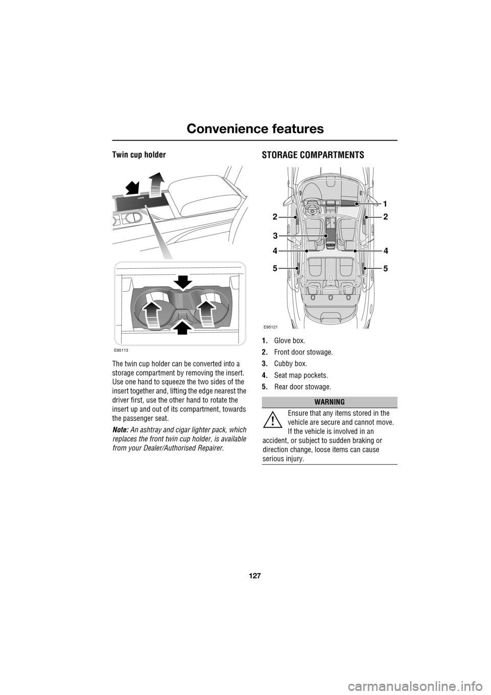
STORAGE COMPARTMENTS
1.Glove box.
2. Front door stowage.
3. Cubby box.
4. Seat map pockets.
5. Rear door stowage.
E95113
WARNING
Ensure that any items stored in the
vehicle are secure and cannot move.
If the vehicle is involved in an
accident, or subject to sudden braking or
direction change, loose items can cause
serious injury.
E95121
22
3
44
5
1
5
Page 128 of 391

Convenience features
128
GARAGE DOOR TRANSCEIVERThe door transceiver is located in the rear-view
mirror. It can be programmed to transmit the
radio frequencies of up to three different
transmitters, which can be used to activate
garage doors, entry ga tes, home lighting,
security systems or other radio frequency
operated devices.
Although this section mainly describes the
procedures for a garage door opener, it also
equally applies to the previously mentioned
applications.
In some countries, this feature is also known
as the HomeLink® Universal Transceiver.
For further information, see Information and
Assistance later in this section.
Before programming
For best results, fit a new battery to the
hand-held transmitter of the garage door
opener (or other device ) before programming.
If your garage door opener receiver (located in
the garage) is equippe d with an antenna,
ensure that the antenna is hanging straight
down.
WARNINGS
Do not use the transceiver with any
garage door opener that lacks the
safety stop and reverse feature as
required by safety standards. Using a garage
door opener without these features increases
risk of serious injury or death.
When programming the transceiver
to a garage door opener or entry gate,
ensure the area is clear. This will
prevent potential harm or damage as the gate
or garage door will activate during the
programme.
CAUTION
This device may suffer from interference
if operated in the vici nity of a mobile or
fixed station transmitter. This interference is
likely to affect the hand-held transmitter as
well as the in-car transceiver.
E95122
CAUTION
When programming a device that may
require you to press and re-press the
hand-held transmitte r (cycle), unplug the
device during the cycling process to prevent
possible motor failure.