2009 JAGUAR XF parking
[x] Cancel search: parkingPage 184 of 391

Towing
184
Diesel engine vehicles
The diesel engine management system
incorporates sensors to determine optimum
performance. It is also designed to protect the
engine when arduous conditions are
encountered during towing. When ambient
temperature exceeds 40°C (104°F), the engine
coolant temperature may increase above
normal operating level. If this occurs, the
management system will initiate a series of
actions to restore norma l operating conditions.
The actions may include:
• A message centre message.
• Engine performance reduction.
• Air conditioning syst em cycling. The
system temperature output will fluctuate
between hot and cold, in order to dissipate
engine heat. If engine overheat persists,
the air conditioning will move to
continuous heat output.
It is advisable to bring the vehicle and trailer to
a convenient stop and allow the engine to idle
until normal temperature is restored. Do not
turn off the engine.
Trailer electrical connection
Note: The rear parking sensors are
automatically disabled when the trailer
electrical conne ction is made using Jaguar
approved towing equipment.
The vehicle's electrical system has been
designed to support all towing requirements,
and comply with legal requirements for the
specific territory in which the vehicle is first
sold.
LEVELLING
To maintain vehicle stabilit y, it is essential that
the trailer is loaded so that it remains parallel to
the ground. This is particularly important when
towing twin axled trailers.
CAUTION
Only connect appr oved electrical
circuits, which are in good condition to
the trailer socket. Connecting incorrect, or
faulty circuits may seriously damage the
vehicle's electrical circuits.
E95506
Page 209 of 391
209
Maintenance
WASHER FLUID CHECK
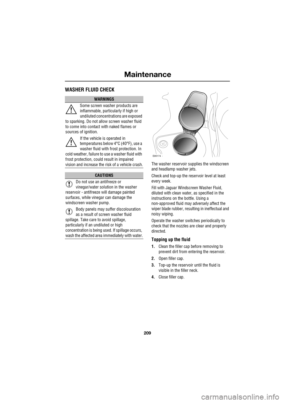
The washer reservoir supplies the windscreen
and headlamp washer jets.
Check and top-up the reservoir level at least
every week.
Fill with Jaguar Windscreen Washer Fluid,
diluted with clean water, as specified in the
instructions on the bottle. Using a
non-approved fluid may adversely affect the
wiper blade rubber, resulting in ineffectual and
noisy wiping.
Operate the washer switches periodically to
check that the nozzles are clear and properly
directed.
Topping up the fluid
1. Clean the filler cap before removing to
prevent dirt from entering the reservoir.
2. Open filler cap.
3. Top-up the reservoir until the fluid is
visible in the filler neck.
4. Close filler cap.
WARNINGS
Some screen washer products are
inflammable, particularly if high or
undiluted concentrations are exposed
to sparking. Do not allow screen washer fluid
to come into contact with naked flames or
sources of ignition.
If the vehicle is operated in
temperatures below 4°C (40°F), use a
washer fluid with frost protection. In
cold weather, failure to use a washer fluid with
frost protection, could result in impaired
vision and increase the risk of a vehicle crash.
CAUTIONS
Do not use an antifreeze or
vinegar/water solution in the washer
reservoir - antifreeze will damage painted
surfaces, while vinegar can damage the
windscreen washer pump.
Body panels may suffer discolouration
as a result of screen washer fluid
spillage. Take care to avoid spillage,
particularly if an undiluted or high
concentration is being us ed. If spillage occurs,
wash the affected area immediately with water.
E95174
Page 220 of 391
Wheels and tyres
220
Tyre pressure compensation chart - high
ambient temperatures
Tyre pressures during long term vehicle
storage
To minimise the possibility and effects of flat
spots during storage, the tyres may be inflated
to the maximum pressure indicated on the tyre
wall.
Note: Before using the st ored vehicle on the
road again, ensure that correct tyre pressures
are restored.
Flat spots
If the vehicle is stati onary for a long period,
when the ambient temperature is high, the
tyres may form flat spots. When the vehicle is
driven, these flat spots will cause a vibration
which will steadily disappear as the tyres warm
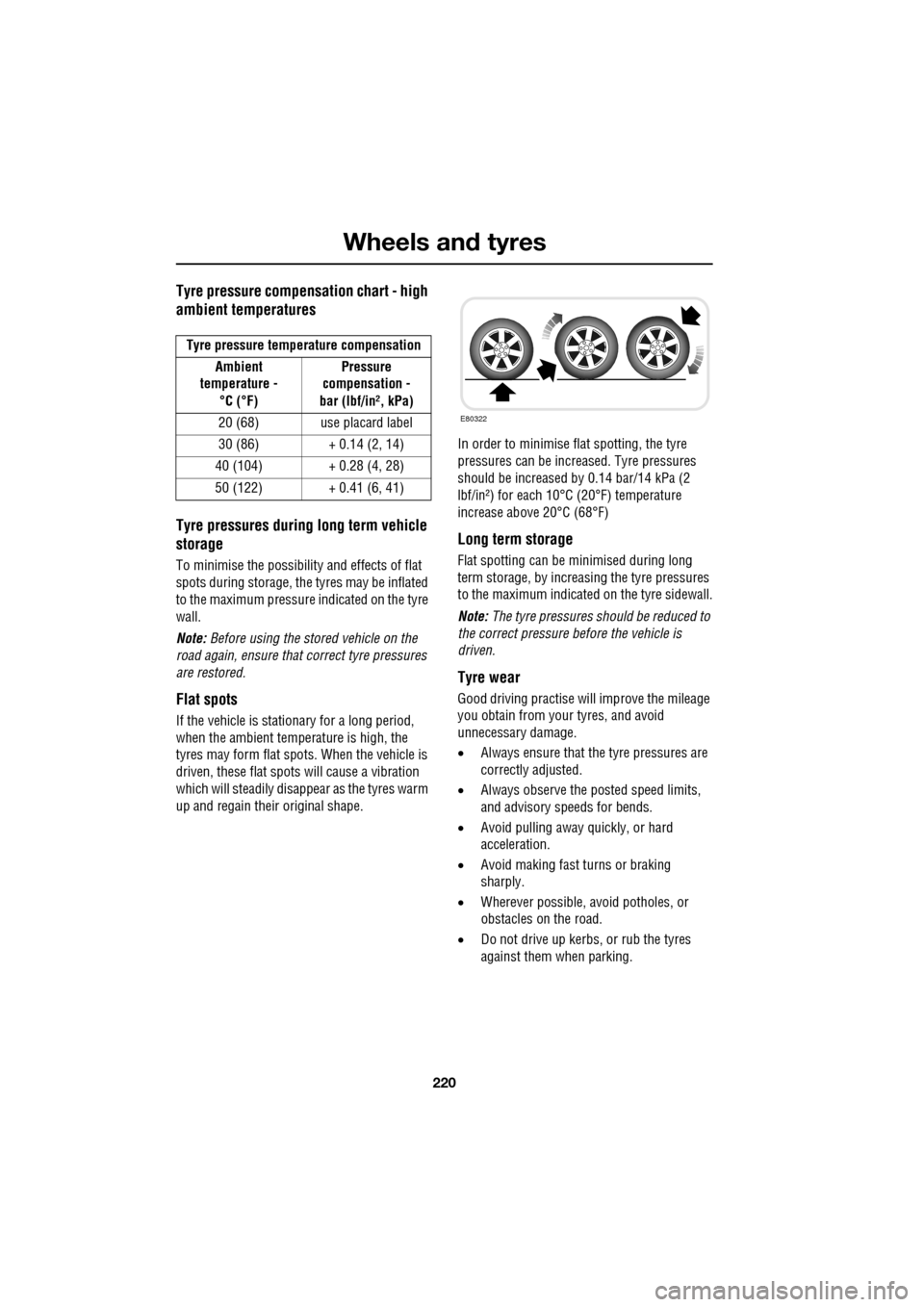
up and regain their original shape. In order to minimise flat spotting, the tyre
pressures can be increa
sed. Tyre pressures
should be increased by 0.14 bar/14 kPa (2
lbf/in²) for each 10°C (20°F) temperature
increase above 20°C (68°F)
Long term storage
Flat spotting can be minimised during long
term storage, by increasing the tyre pressures
to the maximum indicated on the tyre sidewall.
Note: The tyre pressures s hould be reduced to
the correct pressure before the vehicle is
driven.
Tyre wear
Good driving practise will improve the mileage
you obtain from your tyres, and avoid
unnecessary damage.
• Always ensure that the tyre pressures are
correctly adjusted.
• Always observe the posted speed limits,
and advisory speeds for bends.
• Avoid pulling away quickly, or hard
acceleration.
• Avoid making fast turns or braking
sharply.
• Wherever possible, avoid potholes, or
obstacles on the road.
• Do not drive up kerbs, or rub the tyres
against them when parking.
Tyre pressure temperature compensation
Ambient
temperature -
°C (°F) Pressure
compensation -
bar (lbf/in², kPa)
20 (68) use placard label
30 (86) + 0.14 (2, 14)
40 (104) + 0.28 (4, 28)
50 (122) + 0.41 (6, 41)
E80322
Page 227 of 391

227
Wheels and tyres
Wheel changing safety
Before raising the vehicle, or changing a wheel
ensure that you read, and comply with the
following warnings.
WARNINGS
Always find a safe place to stop, off
the highway and away from traffic.
Ensure that the vehicle is on firm level
ground.
Disconnect traile r/caravan from
vehicle.
Switch on the hazard warning lamps.
Ensure that all passengers, and
animals, are out of the vehicle and in
a safe place away from the highway.
Place a warning triangle at a suitable
distance behind th e vehicle, facing
towards oncoming traffic.
Ensure that the front wheels are in the
straight ahead position, and engage
the steering lock.
Apply the parking br ake, and engage
Park (P).
Ensure that the jack is on firm level
ground.
Never place anything between the
jack and the ground, or the jack and
the vehicle.
When one rear wheel is lifted off the
ground the selection P (Park) position
will not prevent the vehicle from
moving and possibly slipping off the jack as
the park brake only operates on the rear
wheels.
Do not start or run the engine while
the vehicle is supported only by a
jack.
The jack is designed for use when
changing a wheel only. Never work
beneath the vehicle with the jack as
the only means of s upport - use vehicle
support stands.
Always chock the wheel diagonally
opposite the wheel to be changed,
using the wheel chock supplied in the
tool kit. Chock the front of a front wheel, or the
rear of a rear wheel.
If jacking the vehicle on a slight slope
is unavoidable, place chocks on the
downhill side of the two opposite
wheels. An additional chock will be
needed.
Take care when lifting the spare
wheel, and removing the punctured
wheel. The wheels are heavy, and can
cause injuries if not handled
correctly.
Remove the spare wheel prior to
jacking the vehicle. To avoid
destabilising the vehicle when raised.
Take care when loosening the wheel
nuts. The wheel brace may slip off if
not properly attached, and the wheel
nuts may give way suddenly. Either
unexpected movement ma y cause an injury.
WARNINGS
Page 228 of 391

Wheels and tyres
228
Wheel changing procedure
1.Ensure that all passengers are in a safe
place, clear of the vehicle.
2. Apply the parking brake and select gear
position P (Park).
3. Ensure that the jack is placed on firm and
level ground.
Observe the instructions printed on the jack.
Use the jack only for lifting the vehicle during
wheel changing and only us e the jack which is
stored in the vehicle.
Before raising the vehi cle slacken but do not
remove the wheel nuts. There are four jacking points on the underside
of the floor. Two indented, triangular indicators
are provided on each sill cover. These indicate
the location for the jack.
The simplest way to correctly locate the jacking
point is to feel along
the sill panel to the
triangular indentation and then fit the jack to
the body, not to the sill panel.
Carefully raise the vehicle by turning the jack
handle. Stop jacking the vehicle when the tyre
just clears the ground. Minimum tyre lift gives
maximum vehicle stability.
Remove the wheel nuts and the wheel.
To remove the centre badge use the plastic
tipped end of the wheel nut wrench handle,
push the centre badge from its housing from
the inside of the wheel.
Push the centre badge into the replacement
wheel. If the temporary use spare wheel is to be
fitted, keep the centre badge safely and fit it to
the repaired full size wheel when it has been
refitted.
Fit the spare wheel and loosely secure with the
wheel nuts.
WARNINGS
Do not attempt to lift the vehicle
unless the jack head is fully engaged
in the jacking point.
Ensure that the park brake is applied.
CAUTION
Ensure before raising the vehicle that
the jack is correctly positioned to avoid
any damage to the vehicle sills or sill panels.
E95185
Page 247 of 391

247
Fuses
Passenger compartment fuse box
Fuse No Rating (amps) Fuse
Colour Circuit
F1 - - Not used.
F2 - - Not used.
F3 20A Blue Driver's seat adjustment.
F4 20A Blue Driver's seat adjustment.
F5 - - Not used.
F6 - - Not used.
F7 - - Not used.
F8 20A Blue Front passenger's seat adjustment.
F9 20A Blue Front passenger's seat adjustment.
F10 20A Blue Left-hand rear door controls.
F11 20A Blue Right-hand rear door controls.
F12 - - Not used.
F13 10A Red Steering column adjust.
F14 - - Not used.
F15 - - Not used.
F16 5A Tan Sunblind.
F17 - - Not used.
F18 - - Not used.
F19 - - Not used.
F20 5A Tan Remote control receiver.
F21 5A Tan Foot brake.
F22 5A Tan Electric parking brake.
F23 5A Tan Driver's seat. Audio system. Auto headlamps. Upper centre console switches.
F24 10A Red Front passen ger seat. Electric windows. Mirror adjustment.
F25 20A Yellow Driver's heated/climate seat
F26 15A Blue Trailer power connector. Road pricing system.
F27 20A Yellow Front passenger's heated/climate seat.
F28 15A Blue Auxiliary power socket.
F29 20A Yellow Keyless entry system.
F30 10A Red Air conditioning.
Page 248 of 391

Fuses
248
Luggage compartment fuse box
F31 15A Blue Sunroof.
F32 5A Tan Jaguar Smart Key docking station.
F33 5A Tan Diagnostic connector.
F34 5A Tan Instrument pack.
F35 15A Blue Interior lamps.
F36 10A Red Suspension system.
Fuse No Rating
(amps) Fuse
Colour Circuit
Fuse No Rating
(amps) Fuse
Colour Circuit
F1 30A Pink Air blower.
F2 30A Pink Electric parking brake.
F3 - - Not used.
F4 - - Not used.
F5 - - Not used.
F6 - - Not used.
F7 30A Pink Heated rear screen.
F8 30A Pink Audio system (Premium audio only).
F9 50A Red RBD link.
F10 40A Green Rear electronic differential (e-Diff).
F11 - - Not used.
F12 - - Not used.
F13 - - Not used.
F14 5A Tan Telephone.
F15 10A Red TV. DVD. DAB radio.
F16 - - Not used.
F17 - - Not used.
F18 - - Not used.
F19 - - Not used.
F20 - - Not used.
F21 - - Not used.
F22 - - Not used.
Page 254 of 391
Vehicle recovery
254
TRANSPORTING THE VEHICLE
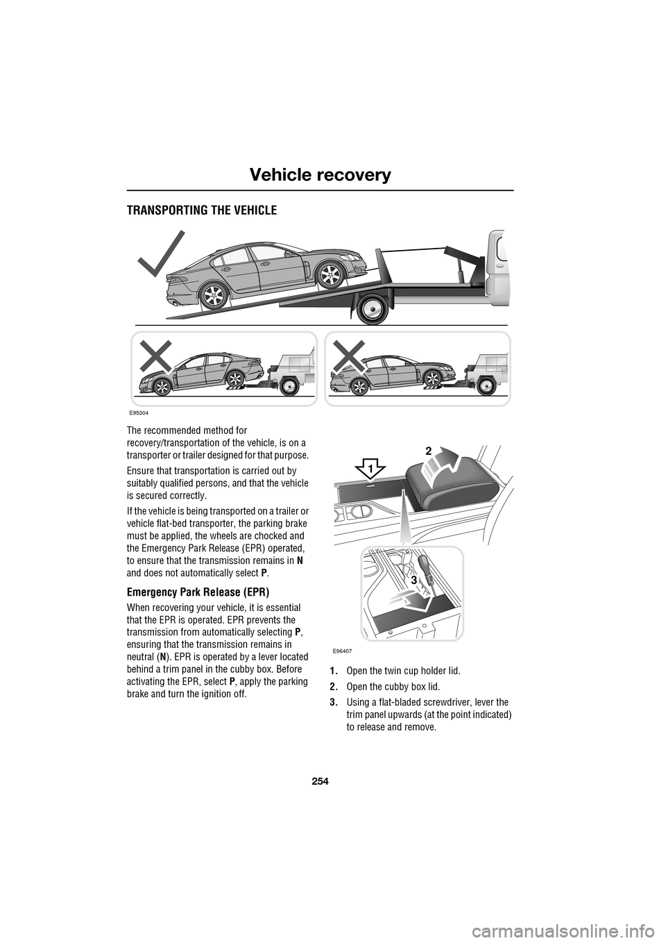
The recommended method for
recovery/transportation of the vehicle, is on a
transporter or trailer de signed for that purpose.
Ensure that transporta tion is carried out by
suitably qualified persons , and that the vehicle
is secured correctly.
If the vehicle is being tr ansported on a trailer or
vehicle flat-bed transporter, the parking brake
must be applied, the wheels are chocked and
the Emergency Park Re lease (EPR) operated,
to ensure that the transmission remains in N
and does not automatically select P.
Emergency Park Release (EPR)
When recovering your vehicle, it is essential
that the EPR is operated. EPR prevents the
transmission from automatically selecting P,
ensuring that the transmission remains in
neutral ( N). EPR is operated by a lever located
behind a trim panel in the cubby box. Before
activating the EPR, select P, apply the parking
brake and turn the ignition off. 1.
Open the twin cup holder lid.
2. Open the cubby box lid.
3. Using a flat-bladed screwdriver, lever the
trim panel upwards (at the point indicated)
to release and remove.
E95304
2
3
E96407
1