2009 JAGUAR XF brakes
[x] Cancel search: brakesPage 168 of 391

Automatic speed limiter (ASL)
168
Note: The message is also displayed at other
times as an information display.
When ASL is selected and a set speed inserted,
the engine will respond normally up to the set
speed. Further accelerator pedal pressure will
not increase the vehicle speed beyond your set
speed, unless kickdown is initiated, in which
case ASL will be suspended.
Suspending ASL
ASL can be suspended by pressing the
CANCEL button ( 3). Applying sudden, rapid
acceleration (kickdown) will also suspend ASL.
Resuming ASL
If ASL has been suspended, it can be reinstated
with a single press of the RESUME button (2),
however, ASL will only reinstate if the vehicle
speed is less than the current speed set in
memory and greater than 30 km/h (18 mph).
The message centre will display an appropriate
message if the vehicle speed is too fast to
resume ASL.
Exceeding the set speed
If the set speed is exceeded, e.g. on a steep
downhill section, th e message centre will
display an appropriate message along with an
amber warning indicator. There are three categor
ies of over limit
displays:
• If the set speed is exceeded by up to 3
km/h (1.8 mph), the message centre will
display the message along with an amber
warning indicator.
• If the set speed is exceeded by more than
7 km/h (4 mph), the message centre will
display the message along with a flashing
red warning indicator.
• If the set speed is exceeded by more than
7 km/h (4 mph) for a duration of four
seconds, the message centre will display
the message along with a flashing red
warning indicator and an audible warning
tone.
Use your brakes to rectify the situation.
ASL unavailable
If ASL is not available due to a fault, the
message centre will display an appropriate
message along with an amber warning
indicator.
The message and warning indicator will display
when the driver attempts to use ASL.
When the ignition is switched off, ASL is
deactivated and any set speed is deleted from
memory.
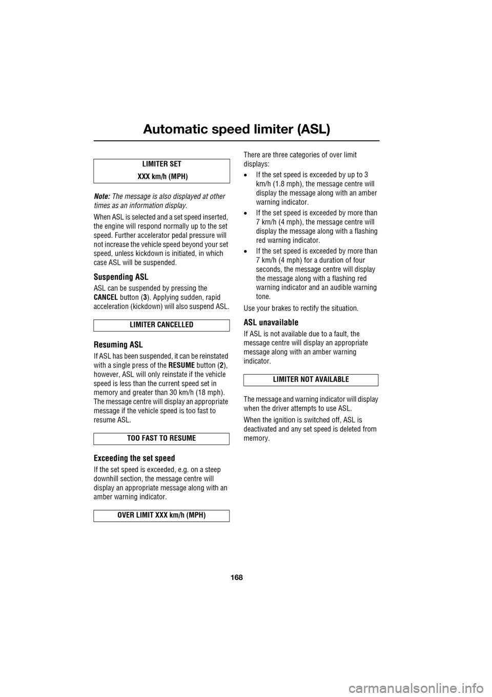
LIMITER SET
XXX km/h (MPH)
LIMITER CANCELLED
TOO FAST TO RESUME
OVER LIMIT XXX km/h (MPH)
LIMITER NOT AVAILABLE
Page 185 of 391

185
Towing
RECOMMENDED TOWING WEIGHTS
Nose/tongue weight must be the greater of
50 kg (110 lbs) or 7% of the actual trailer
weight, up to the maximum tow hitch load.
Nose/tongue weight can be measured using a
proprietary brand of nose weight indicator.
If it is necessary to increase the nose/tongue
weight up to the maximu m allowed, the vehicle
load should be reduced accordingly. This
ensures that the Gross Vehicle Weight (GVW),
and maximum rear axle load, are not exceeded.
Note: When towing the maximum permissible
gross vehicle weight can be increased by a
maximum of 100 kg (220 lb.) provided that the
road speed is limited to 100 km/h (60 mph).
Note: When calculating rear axle loading,
remember that the trailer nose/tongue weight,
the load in the vehicle's luggage area and the
weight of rear seat pa ssengers must all be
added together.
Towing weights - Australia only
The weight of a traile r must not exceed 1.5
times the towing vehicle’s weight. The
nose/tongue weight must be a minimum of 7%
of gross caravan/trai ler weight, up to a
maximum of 350 kg (722 lbs).
ESSENTIAL TOWING CHECKS
• The trailer should be parallel to the ground
when loaded and connected to the vehicle.
• When calculating the laden weight of the
trailer remember to include the weight of
the trailer, plus the weight of the load.
• If the load can be divided between the
vehicle and trailer, loading more weight
into the vehicle will generally improve
stability. Do not exceed the vehicle's
weight limits. See WEIGHTS (page 259).
• Ensure that all applic able regulations and
legislation are complied with when loading
and towing a trailer.
• Increase rear tyre pressures of the towing
vehicle to those for maximum vehicle
loading conditions.
• Ensure trailer tyre pressures are set to
trailer manufacturer' s recommendations.
• If the vehicle is loaded to maximum Gross
Vehicle Weight (GVW) the nose weight is
limited (see Towi ng weights table).
• Ensure that a suitable breakaway cable or
secondary coupling is used. Refer to the
trailer manufacturer' s instructions for
guidance.
• Ensure that the tow ball is secure.
• Check the operation of all trailer lights.
Maximum permissible
towing weights
Unbraked trailers 750 kg (1653 lb.) Trailers with
overrun brakes 1850 kg (4080 lb.)
Nose/Tongue weight 75 kg (165 lb.)
WARNING
Do not exceed the Gross Vehicle
Weight (GVW), m aximum rear axle
weight, maximum trailer weight, or
nose/tongue weight. Exceeding any of these
limits could cause inst ability and loss of
control. See WEIGHTS (page 259).
WARNING
Do not loop the breakaway cable over
the tow ball as it may slide off.
Page 192 of 391

Maintenance
192
GENERAL INFORMATION
Regular systematic maintenance is the key to
ensuring the continued reliability and efficiency
of your vehicle.
Maintenance is the owner's responsibility and
you must ensure that owner maintenance
operations, oil services, inspections and brake
fluid and coolant changes are carried out when
required and according to the manufacturer's
recommendations.
The routine maintenance requirements for your
vehicle are shown in th e Service Portfolio book.
Most of this necessar y workshop maintenance
requires specialised knowledge and
equipment, and should preferably be entrusted
to a Dealer/Authorised Repairer.
Service Portfolio
The Service Portfolio book includes a Service
Record section, which enables a record to be
kept of all the servicing and inspections that are
carried out on the vehicle. This section of the
book also has an area for brake fluid changes
to be recorded.
Ensure your service provider signs and stamps
the book after each se rvice and inspection.
Owner maintenance
In addition to the routine services and
inspections, a number of simple checks must
be carried out more frequently. These checks
can be carried out by th e owner and advice is
given on the pages that follow.
Daily checks
• Operation of lamps, horn, direction
indicators, wipers, washers and warning
indicators.
• Operation of seat belts and brakes.
• Look for fluid deposits underneath the
vehicle that might indicate a leak.
Condensation drips from the air
conditioning is normal.
CAUTION
Severe damage to the electrical system
and electronic components can occur, if
any attempt is made to diagnose faults in the
electrical system using conventional
diagnostic equipment (e .g. the use of test
lamps or low impedanc e voltmeters). The
fitting of any electric al accessory should only
be entrusted to a Deal er/Authorised Repairer.CAUTION
Any significant or sudden drop in fluid
levels, or uneven tyre wear, should be
reported to a qualifie d technician without
delay.
Page 193 of 391

193
Maintenance
Weekly checks
•Engine oil level (non- electronic dipstick
vehicles). See ENGINE OIL CHECK - V6
Petrol engines (page 197).
• Engine coolant check. See ENGINE
COOLANT CHECK (page 204).
• Brake fluid level. See BRAKE FLUID
CHECK (page 206).
• Power steering fluid level. See POWER
STEERING FLUID CHECK (page 208).
• Screen washer fluid level. See WASHER
FLUID CHECK (page 209).
• Tyre pressures and condition. See TYRE
CARE (page 217).
• Operate air conditioning. See AUTOMATIC
CLIMATE CONTROL (page 116).
Note: The engine oil level on V6 petrol engines,
should be checked more frequently if the
vehicle is driven for prolonged periods at high
speeds. The engine oil level on diesel and V8
petrol engines is checked automatically at all
times by the electronic dipstick.
Severe driving conditions
When a vehicle is operated in severe
conditions, more frequent attention must be
paid to servicing requirements.
Severe driving conditions include:
• Driving in dusty and/or sandy conditions.
• Driving on rough and/or muddy roads
and/or wading. •
Driving in extremely hot or cold
conditions.
• Driving in areas using road salt or other
corrosive materials.
• Towing a trailer or driving in mountainous
conditions.
Contact your Dealer/Authorised Repairer for
advice.
Emission control
Your vehicle is fitted with various items of
emission and evaporati ve control equipment,
designed to meet specific territorial
requirements. You should be aware that
unauthorised replacemen t, modification or
tampering with this equipment by an owner or
repair shop, may be unlawful and subject to
legal penalties.
In addition, engine se ttings must not be
tampered with. These have been established to
ensure that your vehicle complies with
stringent exhaust em ission regulations.
Incorrect engine settings may adversely affect
exhaust emissi ons, engine performance and
fuel consumption. The y may also cause high
temperatures, which will result in damage to
the catalytic converter and the vehicle.
Road testing dynamometers (rolling
roads)
Because your vehicle is equipped with anti-lock
brakes, it is essential that any dynamometer
testing is carried out only by a qualified person,
familiar with the dynamometer testing and
safety procedures practised by
Dealers/Authorised Repairers.
CAUTION
Ensure that you take notice of any
message centre information and
warnings relating to engi ne oil level (V8 petrol
and diesel engines only). Top-up the level
when advised to do so. See ENGINE OIL
CHECK - V8 Petrol engines (page 199).
Page 206 of 391

Maintenance
206
BRAKE FLUID CHECK
If the quantity of fluid in the brake
reservoir drops below the
recommended level, a red warning
indicator in the instrume nt pack will illuminate
and the message BRAKE FLUID LOW will be
displayed in the message centre.
Note: If the warning indicator illuminates or the
message is displayed, while the vehicle is being
driven, stop the vehicle as soon as safety
permits by gently applying the brakes. Check
and top-up the fluid level if necessary.
Checking the fluid level
With the vehicle on level ground, check the
fluid level at least every week (more frequently
in high mileage or arduous operating
conditions).
The brake fluid reservoi r is located beneath a
cover on the raised platform to the rear of the
main underbonnet area. See ENGINE
COMPARTMENT OVERVIEW (page 196).
1. Release the catch.
2. Lift the cover forwards, then pull
rearwards, to release the hinges.
3. Clean the filler cap with a clean, dry cloth
before removing, to prevent dirt or
moisture from entering the reservoir.
WARNING
Seek qualified assistance immediately
if brake pedal travel is unusually long,
unusually short or if there is any
significant loss of br ake fluid. Driving under
such conditions could result in extended
stopping distances or co mplete brake failure.
WARNINGS
Brake fluid is highly toxic - keep
containers sealed a nd out of reach of
children. If accidental consumption is
suspected, seek medical attention
immediately.
If the fluid comes into contact with
the skin or eyes, rinse immediately
with plenty of water.
Brake fluid is highl y inflammable. Do
not allow brake fluid to come into
contact with naked flames or other
sources of ignition (e.g. a hot engine) - a fire
may result.
Do not drive the vehicle with the fluid
level below the MIN mark.
E95164
1
2
Page 238 of 391

Wheels and tyres
238
TYRE GLOSSARY
lbf/in² or psi
Pounds per square inch, an imperial unit of
measure for pressure.
kPa
Kilo Pascal, a metric unit of measure for
pressure.
Cold tyre pressure
The air pressure in a tyre which has been
standing in excess of th ree hours, or driven for
less than 1.6 km (1 mile).
Maximum inflation pressure
The maximum pressure to which the tyre
should be inflated. This pressure is given on
the tyre side wall in lbf/in² (psi) and kPa.
Note: This pressure is the maximum allowed
by the tyre manufacturer. It is not the pressure
recommended for use.
Kerb weight
The weight of a standa rd vehicle, including a
full tank of fuel, any optional equipment fitted,
and with the correct coolant and oil levels.
Gross vehicle weight
The maximum permissible weight of a vehicle
with driver, passen gers, load, luggage,
equipment, and towbar load.
Accessory weight
The combined weight (in excess of those items
replaced) of items available as factory installed
equipment.
Production options weight
The combined weight of options installed
which weigh in excess of 1.4 kg (3 lb) more
than the standard items that they replaced, and
are not already considered in kerb or accessory
weights. Items such as heavy duty brakes, high
capacity battery, special trim etc.
Vehicle capacity weight
The number of seats multiplied by 68 kg
(150 lb) plus the rated amount of load/luggage.
Maximum loaded vehicle weight
The sum of kerb wei ght, accessory weight,
vehicle capacity weig ht, plus any production
option weights.
Rim
The metal support for a ty re, or tyre and tube,
upon which the tyre beads are seated.
Bead
The inner edge of a tyre th at is shaped to fit to
the rim and form an air tight seal. The bead is
constructed of steel wires which are wrapped,
or reinforced, by the ply cords.
Page 245 of 391

245
Fuses
FUSE SPECIFICATION CHART
Engine compartment fuse box
Fuse No Rating (amps) Fuse
Colour Circuit
F1 - - Not used.
F2 - - Not used.
F3 20A Blue Emissions system (petrol only).
F4 20A Blue Emissions system (petrol only).
F5 40A Green Anti-lock brake pump.
F6 30A Pink Power wash pump.
F7 - - Not used.
F8 - - Not used.
F9 50A Red Engine management.
F10 - - Not used.
F11 - - Not used.
F12 50A Red Secondary air in jection (petrol only).
F13 30A Pink Wipers.
F14 30A Pink Starter solenoid.
F15 40A Green Screen heater.
F16 40A Green Screen heater.
F17 80A Black Radiator fan. (V6 petrol only)
F18 60A Yellow Glow plugs (diesel only).
F19 - - Not used.
F20 15A Blue Horn.
F21 25A Clear Anti-lock brakes.
F22 15A Blue Cigar lighter.
F23 - - Not used.
F24 5A Tan Adaptive cruise control.
F25 10A Red Anti-lock brakes.
F26 10A Red Engine manage ment. JaguarDrive selector. Transmission
control module.
F27 5A Tan Diesel - Engine management.
F27 5A Tan Petrol - Secondary air injection.
Page 256 of 391

Vehicle recovery
256
TOWING THE VEHICLE ON FOUR
WHEELS
Note: The recommended recovery method is
to raise all four wheels.
Towing procedure
1. The vehicle should be parked on firm level
ground, with the parking brake on, and the
gear selector in P (Park).
2. Secure the towing attachment from the
recovery vehicle to the front towing eye.
See TOWING POINTS (page 253).
3. Dock the Jaguar Smart Key and switch on
the ignition. See GENERAL INFORMATION
(page 132). 4.
Apply the foot brake and release the
parking brake.
5. With the foot brake st ill applied, activate
the Emergency Park Release (EPR).
See TRANSPORTING THE VEHICLE
(page 254).
6. The vehicle can now be towed a maximum
of 0.8 km (0.5 miles) at a maximum speed
of 48 kmh (30 mph).
7. Upon arrival at the destination, ensure
wherever possible that the vehicle is
parked on firm level ground.
8. Lower the Emergency Park Release (EPR)
lever, to cancel EP R and to re-engage P
(Park).
9. Apply the parking brake.
10. Switch off the ignition and remove the
Jaguar Smart Key.
11. Remove the towing attachment from the
towing eye.
WARNINGS
Ensure that the remote control
remains docked whilst the vehicle is
being towed. Removing the remote
control will engage the steering lock, which
will prevent the vehicle from steering
correctly.
If the engine cannot be run whilst the
vehicle is being towed, there will be
no power assistance for the steering
or brakes. This will result in greater effort
being required to steer or slow the vehicle, and
greatly increased stopping distances.
CAUTIONS
The vehicle should only be towed in a
forward direction with all four wheels on
the ground.
The vehicle should only be towed for a
maximum of 0.8 km (0.5 miles), at a
maximum speed of 48 km/h (30 mph). Towing
for a greater distance or at a higher speed, may
result in serious damage to the transmission.
CAUTION
Leaving the ignition switched on for
extended periods will cause the battery
to drain.
WARNING
Use extreme caution when detaching
towing equipment. Vehicle movement
is possible which can result in serious
injuries.