2009 JAGUAR XF parking brake
[x] Cancel search: parking brakePage 146 of 391

Brakes
146
Emergency Brake Assist (EBA)
The EBA system measures the rate at which the
brake pressure increases. If the system detects
an emergency braking situation, EBA
automatically init iates full braking effect. This
can reduce stopping dist ances in critical
situations.
EBA stops operating as soon as the brake pedal
is released.
EBA is part of the Dynamic Stability
Control (DSC) system and a fault
with the EBA system is indicated by
the amber DSC warning indicator illuminating
and DSC NOT AVAILABLE (with amber
backlight) displaying in the message centre.
Seek qualified assistan ce as soon as possible.
Brake vacuum assist
(V6 petrol models only)
When the engine is cold and/or engine vacuum
is low, Brake vacuum assist provides additional
brake pedal assistance. When the function is
operating, a pulsation ma y be felt through the
brake pedal - this is not a cause for concern.
A fault is indicate d by the message BRAKE
ASSIST FAULT (with amber backlight)
appearing in the message centre. Increased
brake pedal effort may be required to slow the
vehicle when the engine is cold and/or engine
vacuum is low. Seek qualified assistance.
ELECTRIC PARKING BRAKE (EPB)
The switch which operate s the parking brake is
mounted on the centre c onsole to the rear of
the gear selector.
To engage the parking brake (1): Pull the
parking brake switch up wards and release. The
switch will return to the neutral position. The
Parking brake warning and Brake fluid low
warning indicator on the instrument panel will
illuminate.
The Drive Away Release feature allows the
parking brake to release automatically as the
vehicle is driven away.
To disengage the parking brake (2): With the
ignition system on or with the engine running,
apply the foot brake and press the parking
brake switch down.
If the parking brake is a pplied while the vehicle
is stationary and D or R is selected, applying
the throttle will auto matically release the
parking brake.
The parking brake is also automatically
released when the gear selector is moved from
the P position.
WARNING
The EBA system is an additional
safety system; it is not intended to
relieve the driver of his or her
responsibility for exercising due care and
attention when driving.12
E95148
Page 147 of 391

147
Brakes
If the parking brake is inadvertently applied
when the vehicle is moving at above 3 km/h
(1.8 mph), PARK BRAKE APPLIED is displayed
in the message centre, the warning indicator in
the instrument panel will illuminate and a
warning chime will sound.
If the parking brake is a pplied whilst the vehicle
is moving, releasing the switch will disengage
the parking brake. The parking brake cannot be
applied when the vehicle is moving, if the
accelerator pedal is pressed.
Note: If the vehicle is in motion, the parking
brake should only be used as an emergency
brake.
The warning indicator in the instrument panel
will remain on for a short time, if the parking
brake is applied when the ignition system is
reverted to the convenience mode.
If a fault in the system is detected,
the amber brake warning indicator
will illuminate and PARK BRAKE
FAULT or CANNOT APPLY PARK BRAKE will
be displayed in the message centre. Seek
qualified assistance as soon as possible.
If the battery has been discharged or
disconnected, APPLY FOOT AND PARK BRAKE
will be displayed in the message centre when
the ignition is next switched on. Depress the
foot brake and pull the parking brake switch up
to apply the parking brake. This is required to
reset the parking brake system. The parking
brake will now function correctly.
CAUTION
Always apply the parking brake when
the vehicle is parked.
Page 151 of 391

151
Parking aid
The front or rear warning tone will become
continuous when the obstacle is detected at or
within 300 mm (12 inches) from the vehicle.
Note: The outer front and rear sensors will
switch off if the distance to an object increases
or remains constant for 3 seconds. The
sensors will reactivate automatically if a new
object is detected with in the operating range,
or if the distance to the original object reduces.
Rear fitted accessories
Particular care must be taken when reversing
with rear fitted accessories e.g. bicycle carrier,
as the rear park assist will only indicate the
distance from the bumper to the obstacle.
Cleaning the sensors
Do not clean the sensors with abrasive or sharp
objects or materials.
For reliable operation, th e sensors in the front
and rear bumpers should be kept free from ice,
frost and grime.
When using a high pressure spray the sensors
should only be sprayed br iefly and not from a
distance of less than 200 mm (8 inches).
System fault
If the system has a fault when engaging reverse
gear or turning on the ignition, then a single,
three second tone will be heard (only once per
ignition cycle) and a pop-up warning will
appear on the touch-scre en. If both front and
rear parking aids are fitted, the warning
indicator in the parking aid switch will flash for
three seconds and then switch off, if a fault is
detected.
If a fault is detected, the system is
automatically disabled.
The parking aid may sound spurious tones if it
detects a frequency tone using the same band
as the sensors (e.g. air brakes).
Page 227 of 391

227
Wheels and tyres
Wheel changing safety
Before raising the vehicle, or changing a wheel
ensure that you read, and comply with the
following warnings.
WARNINGS
Always find a safe place to stop, off
the highway and away from traffic.
Ensure that the vehicle is on firm level
ground.
Disconnect traile r/caravan from
vehicle.
Switch on the hazard warning lamps.
Ensure that all passengers, and
animals, are out of the vehicle and in
a safe place away from the highway.
Place a warning triangle at a suitable
distance behind th e vehicle, facing
towards oncoming traffic.
Ensure that the front wheels are in the
straight ahead position, and engage
the steering lock.
Apply the parking br ake, and engage
Park (P).
Ensure that the jack is on firm level
ground.
Never place anything between the
jack and the ground, or the jack and
the vehicle.
When one rear wheel is lifted off the
ground the selection P (Park) position
will not prevent the vehicle from
moving and possibly slipping off the jack as
the park brake only operates on the rear
wheels.
Do not start or run the engine while
the vehicle is supported only by a
jack.
The jack is designed for use when
changing a wheel only. Never work
beneath the vehicle with the jack as
the only means of s upport - use vehicle
support stands.
Always chock the wheel diagonally
opposite the wheel to be changed,
using the wheel chock supplied in the
tool kit. Chock the front of a front wheel, or the
rear of a rear wheel.
If jacking the vehicle on a slight slope
is unavoidable, place chocks on the
downhill side of the two opposite
wheels. An additional chock will be
needed.
Take care when lifting the spare
wheel, and removing the punctured
wheel. The wheels are heavy, and can
cause injuries if not handled
correctly.
Remove the spare wheel prior to
jacking the vehicle. To avoid
destabilising the vehicle when raised.
Take care when loosening the wheel
nuts. The wheel brace may slip off if
not properly attached, and the wheel
nuts may give way suddenly. Either
unexpected movement ma y cause an injury.
WARNINGS
Page 228 of 391

Wheels and tyres
228
Wheel changing procedure
1.Ensure that all passengers are in a safe
place, clear of the vehicle.
2. Apply the parking brake and select gear
position P (Park).
3. Ensure that the jack is placed on firm and
level ground.
Observe the instructions printed on the jack.
Use the jack only for lifting the vehicle during
wheel changing and only us e the jack which is
stored in the vehicle.
Before raising the vehi cle slacken but do not
remove the wheel nuts. There are four jacking points on the underside
of the floor. Two indented, triangular indicators
are provided on each sill cover. These indicate
the location for the jack.
The simplest way to correctly locate the jacking
point is to feel along
the sill panel to the
triangular indentation and then fit the jack to
the body, not to the sill panel.
Carefully raise the vehicle by turning the jack
handle. Stop jacking the vehicle when the tyre
just clears the ground. Minimum tyre lift gives
maximum vehicle stability.
Remove the wheel nuts and the wheel.
To remove the centre badge use the plastic
tipped end of the wheel nut wrench handle,
push the centre badge from its housing from
the inside of the wheel.
Push the centre badge into the replacement
wheel. If the temporary use spare wheel is to be
fitted, keep the centre badge safely and fit it to
the repaired full size wheel when it has been
refitted.
Fit the spare wheel and loosely secure with the
wheel nuts.
WARNINGS
Do not attempt to lift the vehicle
unless the jack head is fully engaged
in the jacking point.
Ensure that the park brake is applied.
CAUTION
Ensure before raising the vehicle that
the jack is correctly positioned to avoid
any damage to the vehicle sills or sill panels.
E95185
Page 247 of 391

247
Fuses
Passenger compartment fuse box
Fuse No Rating (amps) Fuse
Colour Circuit
F1 - - Not used.
F2 - - Not used.
F3 20A Blue Driver's seat adjustment.
F4 20A Blue Driver's seat adjustment.
F5 - - Not used.
F6 - - Not used.
F7 - - Not used.
F8 20A Blue Front passenger's seat adjustment.
F9 20A Blue Front passenger's seat adjustment.
F10 20A Blue Left-hand rear door controls.
F11 20A Blue Right-hand rear door controls.
F12 - - Not used.
F13 10A Red Steering column adjust.
F14 - - Not used.
F15 - - Not used.
F16 5A Tan Sunblind.
F17 - - Not used.
F18 - - Not used.
F19 - - Not used.
F20 5A Tan Remote control receiver.
F21 5A Tan Foot brake.
F22 5A Tan Electric parking brake.
F23 5A Tan Driver's seat. Audio system. Auto headlamps. Upper centre console switches.
F24 10A Red Front passen ger seat. Electric windows. Mirror adjustment.
F25 20A Yellow Driver's heated/climate seat
F26 15A Blue Trailer power connector. Road pricing system.
F27 20A Yellow Front passenger's heated/climate seat.
F28 15A Blue Auxiliary power socket.
F29 20A Yellow Keyless entry system.
F30 10A Red Air conditioning.
Page 248 of 391

Fuses
248
Luggage compartment fuse box
F31 15A Blue Sunroof.
F32 5A Tan Jaguar Smart Key docking station.
F33 5A Tan Diagnostic connector.
F34 5A Tan Instrument pack.
F35 15A Blue Interior lamps.
F36 10A Red Suspension system.
Fuse No Rating
(amps) Fuse
Colour Circuit
Fuse No Rating
(amps) Fuse
Colour Circuit
F1 30A Pink Air blower.
F2 30A Pink Electric parking brake.
F3 - - Not used.
F4 - - Not used.
F5 - - Not used.
F6 - - Not used.
F7 30A Pink Heated rear screen.
F8 30A Pink Audio system (Premium audio only).
F9 50A Red RBD link.
F10 40A Green Rear electronic differential (e-Diff).
F11 - - Not used.
F12 - - Not used.
F13 - - Not used.
F14 5A Tan Telephone.
F15 10A Red TV. DVD. DAB radio.
F16 - - Not used.
F17 - - Not used.
F18 - - Not used.
F19 - - Not used.
F20 - - Not used.
F21 - - Not used.
F22 - - Not used.
Page 254 of 391

Vehicle recovery
254
TRANSPORTING THE VEHICLE
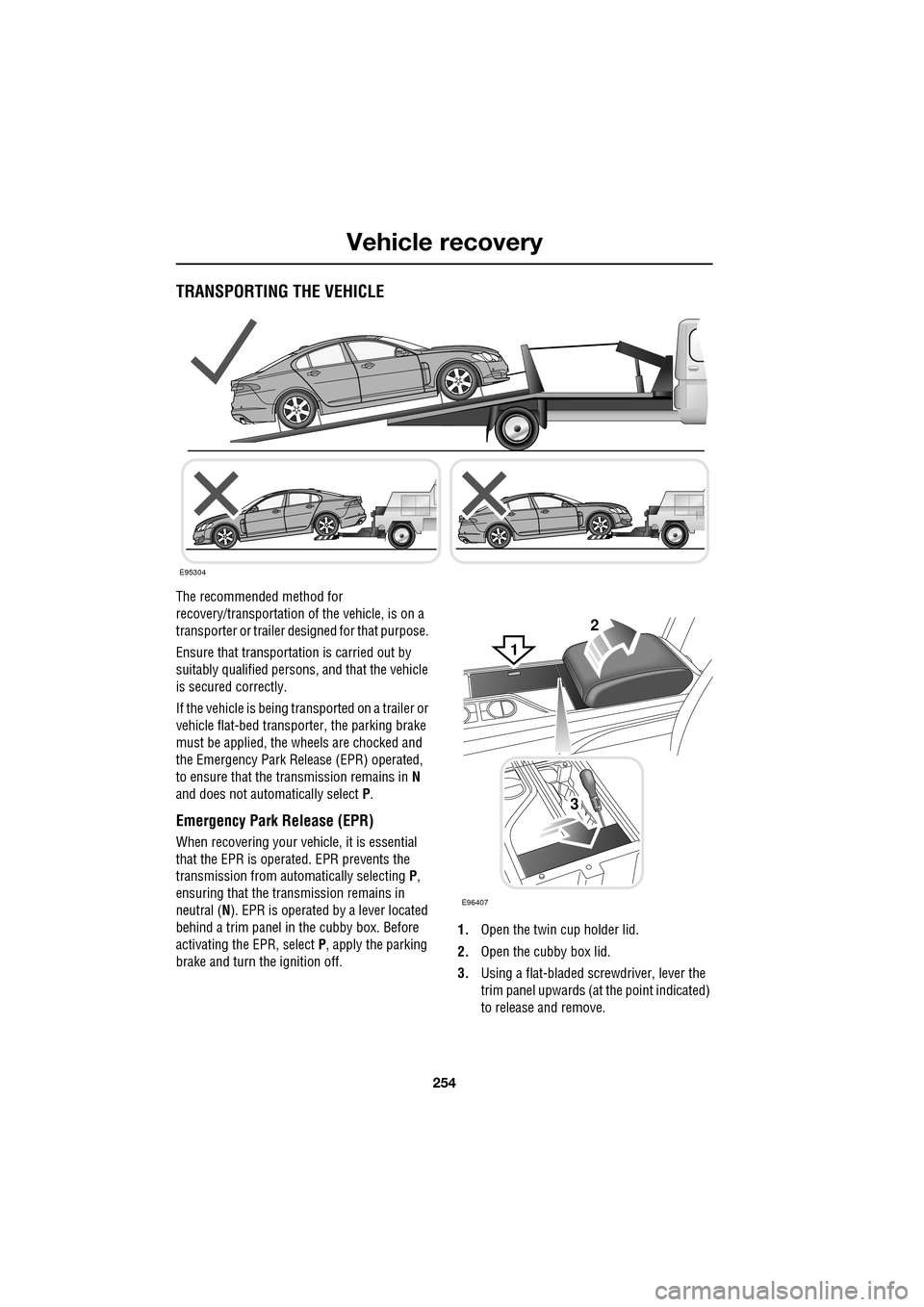
The recommended method for
recovery/transportation of the vehicle, is on a
transporter or trailer de signed for that purpose.
Ensure that transporta tion is carried out by
suitably qualified persons , and that the vehicle
is secured correctly.
If the vehicle is being tr ansported on a trailer or
vehicle flat-bed transporter, the parking brake
must be applied, the wheels are chocked and
the Emergency Park Re lease (EPR) operated,
to ensure that the transmission remains in N
and does not automatically select P.
Emergency Park Release (EPR)
When recovering your vehicle, it is essential
that the EPR is operated. EPR prevents the
transmission from automatically selecting P,
ensuring that the transmission remains in
neutral ( N). EPR is operated by a lever located
behind a trim panel in the cubby box. Before
activating the EPR, select P, apply the parking
brake and turn the ignition off. 1.
Open the twin cup holder lid.
2. Open the cubby box lid.
3. Using a flat-bladed screwdriver, lever the
trim panel upwards (at the point indicated)
to release and remove.
E95304
2
3
E96407
1