2009 JAGUAR XF headlamp
[x] Cancel search: headlampPage 79 of 391

79
Lighting
HEADLAMP LEVELLING
Halogen headlamps
Use the headlamp levelling control to account
for vehicle loading changes.
Xenon headlamps
Headlamp levelling is adjusted automatically if
Xenon headlamps are fitted, to account for
vehicle load conditions, to avoid dazzling
oncoming drivers.
CORNERING OR STATIC BENDING
LAMPS
Cornering or static bending lamps are angled
outwards from the centre line of the vehicle.
These lamps broaden the beam of the
headlamps when cornering during normal
night driving.
1. Light spread of a vehicle not fitted with
static bending lamps.
2. Light spread of a vehicle fitted with static
bending lamps
The system switches on the lamp if it has
received an input from the vehicle's direction
indicator. Only the lamp on the same side as
the operating direction indicator illuminates.
The system only operate s with the ignition
switched on.
Vehicle load Switch position
Driver only 0
Driver and front seat
passenger
1
Driver and pa ssengers in
all seats 2
Maximum gross vehicle
weight 2
Maximum rear axle load 2 or 3
JAG1334
1
2
JAG0923
Page 81 of 391

81
Lighting
Note: For lamps controlled by proximity
sensors, the wearing of gloves may interfere
with operation. If you are wearing gloves, it
may be necessary to touch the proximity
switch to operate the lamps.
Ambience lighting
Ambience lighting. Automatically illuminates
when the headlamps are on. Ambience lighting
creates a blue glow ar ound the centre console
and front door armrests.
Luggage compartment lamp
Automatically illuminates when the luggage
compartment is opened.
APPROACH LAMPS
This feature is activated by pressing
the headlamp icon button on the
Jaguar Smart Key. See USING THE
REMOTE CONTROL (page 17). The headlamps
will remain on for 25 seconds or until the
button is pressed again, or until the engine
START/STOP button is pressed.
REMOVING A HEADLAMP
1. Open the bonnet. See OPENING AND
CLOSING THE BONNET (page 195).
2. Remove the two bolts from the top of the
headlamp unit.
3. Remove the retaining bolt located in the
wheel arch.
Note: To improve access to the wheel arch,
turn the steering wheel to full lock, in the
direction of the affected headlamp.
4. Pull the headlamp away slightly from the
body of the vehicle.CAUTION
It is recommended that the following
procedure should only be attempted by
a qualified technician. If in doubt, consult your
Dealer/Authorised Repairer.
Do not place the removed lamp unit face
down on hard or abrasive surfaces.
Doing so may scratch the surface of the lens.
3
2
2
E94719
2
4
Page 82 of 391

Lighting
82
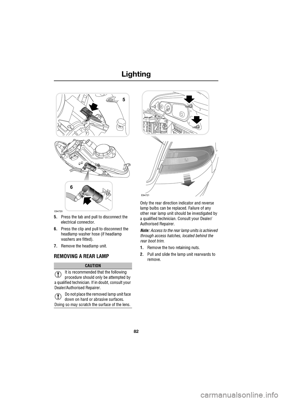
5.Press the tab and pull to disconnect the
electrical connector.
6. Press the clip and pull to disconnect the
headlamp washer hose (if headlamp
washers are fitted).
7. Remove the headlamp unit.
REMOVING A REAR LAMP
Only the rear directio n indicator and reverse
lamp bulbs can be repl aced. Failure of any
other rear lamp unit should be investigated by
a qualified technician. Consult your Dealer/
Authorised Repairer.
Note: Access to the rear lamp units is achieved
through access hatche s, located behind the
rear boot trim.
1. Remove the two retaining nuts.
2. Pull and slide the lamp unit rearwards to
remove.
CAUTION
It is recommended that the following
procedure should only be attempted by
a qualified technician. If in doubt, consult your
Dealer/Authorised Repairer.
Do not place the removed lamp unit face
down on hard or abrasive surfaces.
Doing so may scratch the surface of the lens.
E94720
5
6
E94721
Page 83 of 391

83
Lighting
CHANGING A BULB
General information
Note: In certain markets its a legal requirement
to carry spare bulbs. A replacement bulb kit is
available as an approved accessory from your
Dealer/Authorised Repairer.
Halogen bulbs
Halogen bulbs are used for main beam and
dipped beam headlamps. Take care not to
touch the glass part of the bulb with your
fingers; always use a cl oth to handle the bulb.
If necessary use methylated spirits to remove
finger prints.
Xenon lamps
Seek advice about the correct
disposal of Xenon lamp units from
your Dealer/Authorised Repairer, or
your local authority.
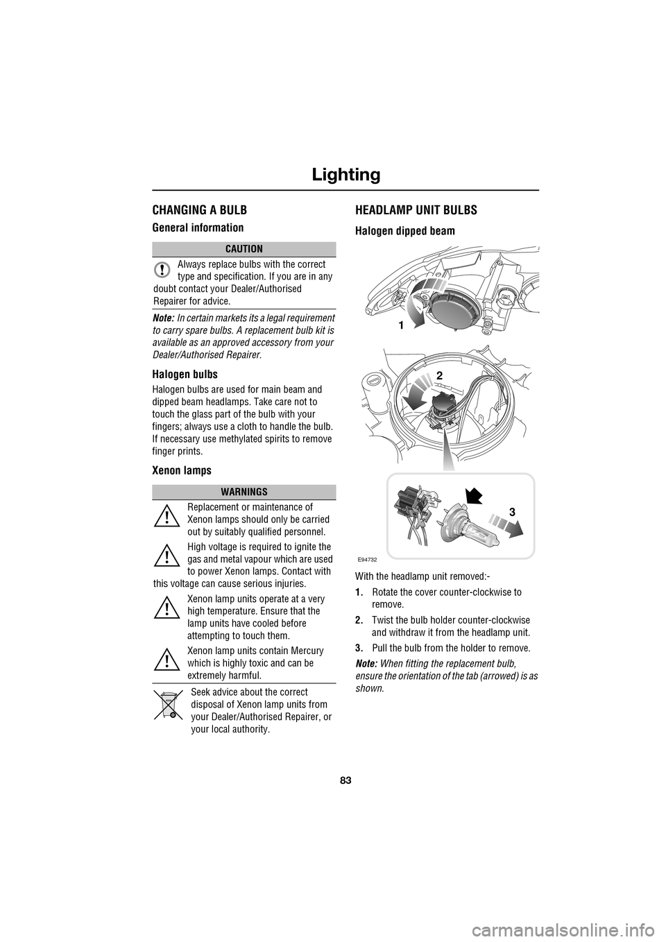
HEADLAMP UNIT BULBS
Halogen dipped beam
With the headlamp unit removed:-
1. Rotate the cover counter-clockwise to
remove.
2. Twist the bulb holder counter-clockwise
and withdraw it from the headlamp unit.
3. Pull the bulb from the holder to remove.
Note: When fitting the replacement bulb,
ensure the orientation of the tab (arrowed) is as
shown.
CAUTION
Always replace bulbs with the correct
type and specification. If you are in any
doubt contact your Dealer/Authorised
Repairer for advice.
WARNINGS
Replacement or maintenance of
Xenon lamps should only be carried
out by suitably qualified personnel.
High voltage is required to ignite the
gas and metal vapour which are used
to power Xenon lamps. Contact with
this voltage can cause serious injuries.
Xenon lamp units operate at a very
high temperature. Ensure that the
lamp units have cooled before
attempting to touch them.
Xenon lamp units contain Mercury
which is highly toxic and can be
extremely harmful.
E94732
1
2
3
Page 84 of 391

Lighting
84
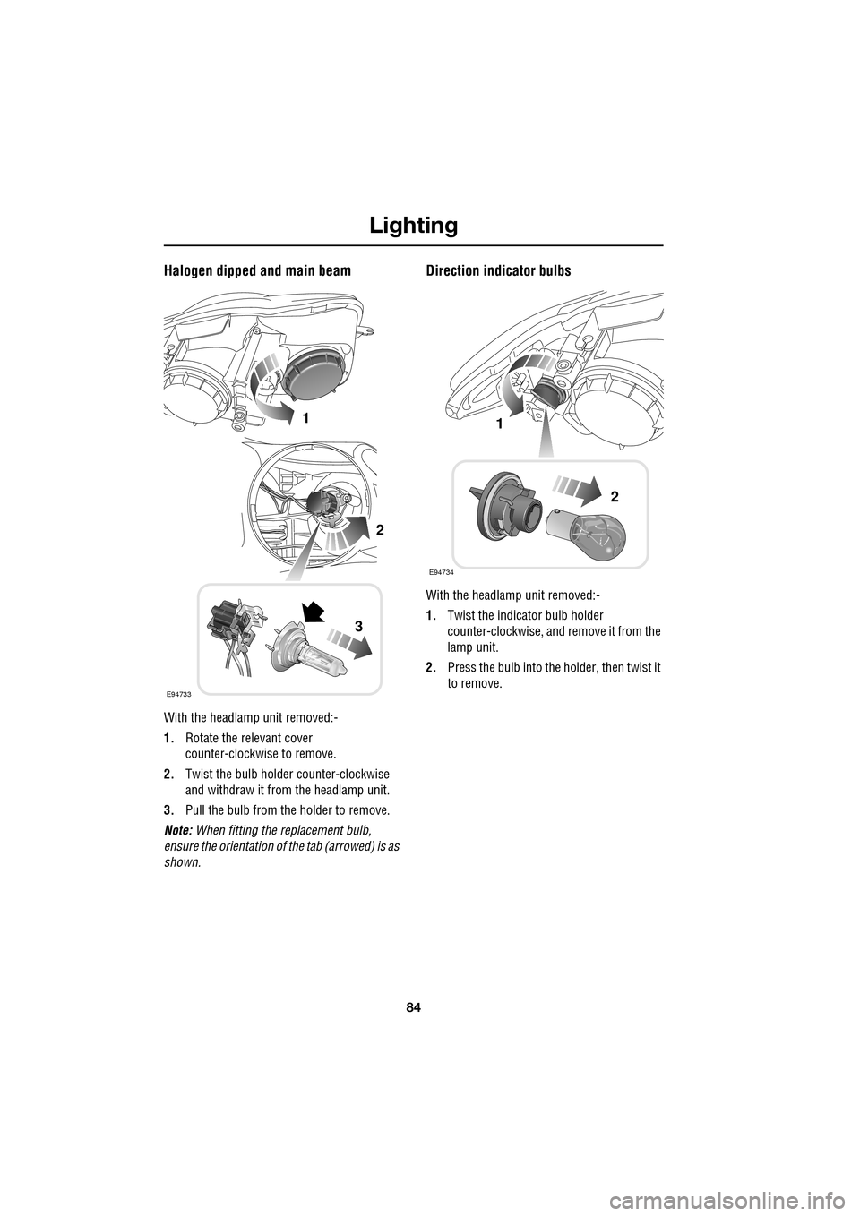
Halogen dipped and main beam
With the headlamp unit removed:-
1.Rotate the relevant cover
counter-clockwise to remove.
2. Twist the bulb holder counter-clockwise
and withdraw it from the headlamp unit.
3. Pull the bulb from the holder to remove.
Note: When fitting the replacement bulb,
ensure the orientation of the tab (arrowed) is as
shown.
Direction indicator bulbs
With the headlamp unit removed:-
1. Twist the indicator bulb holder
counter-clockwise, and remove it from the
lamp unit.
2. Press the bulb into the holder, then twist it
to remove.
E94733
1
2
3
E94734
1
2
Page 87 of 391

87
Lighting
BULB SPECIFICATION CHART
Note: The tail lamp, stop lamp, rear fog lamps,
rear side lamps, side repeater lamps and high
mounted stop lamp, ar e LED units and are
non-serviceable. If an y of these lamps should
fail, they should be investigated by qualified
personnel. Consult your Dealer/Authorised
Repairer.
CAUTION
Before attempting to replace a bulb,
ensure that both the affected lamp and
the vehicle's ignition are turned off. If the
circuit is live a short circuit can occur which
may damage the vehicle's electrical system.
Lamp Specification Power (Watts)
Halogen headlamp (Low and High beam) H7/H755/55
Xenon headlamp (Low and High beam) D1S/H735/55
Front side lamps W5W HCB5
Front direction indicators PY21W21
Rear direction indicators PY19W19
Reverse lamps PS19W19
Number plate lamps W5W5
Interior overhead lamps W6WX6
Footwell lamps W5W5
Luggage lamp S10W10
Tailgate lamps W5W5
Glove box lamp W5W5
Vanity mirror lamp 2 x TS1.3W1.3
Page 90 of 391

Wipers and washers
90
Low screen wash
If the low washer fluid warning is on, the
windscreen wipers will not operate when the
wash/wipe is activated, even though there may
be washer fluid remaining in the reservoir
which is sprayed onto the screen. This is to
prevent damage to the wiper blades, scratching
of the glass or smearing dirt across the screen.
Normal, fast or single wipe can be selected
manually, to clear any spray from the
windscreen.
Timed jet function
If the timed jet func tion is configured,
the washer jets will only operate on the
up stroke of the wipers.
This function can be enabled/disabled by your
Dealer/Authorised Repairer.
Drip wipe
If the drip wipe function is configured,
the wipers will operate four seconds
after a wash wipe cycle has finished, to
clear any remaining drips from the windscreen.
This function can be enabled/disabled by your
Dealer/Authorised Repairer.
Blocked jets
If a washer jet becomes blocked, use a thin
strand of wire to unblock the jet by inserting
the wire into the jet. Ensure that the wire is
completely remove d after unblocking.
HEADLAMP WASHERS
Headlamp power wash operates automatically
with the windscreen wash, and will only
operate if the headlamps are switched on and
there is sufficient washer fluid in the reservoir.
Headlamp wash operates with every fourth
operation of the screen wa shers, provided that
ten minutes have elapsed since the last
operation of the headlamp washers.
Note: The power wash sequence is reset when
the headlamps or the ignition are turned off.
Note: Headlamp power wash is inhibited when
the low washer fluid warning is on.
CHECKING THE WIPER BLADES
The wiping edge of the blades should be
checked and cleaned periodically. Check the
blade rubber and replace the blade immediately
if cracks, splits or roughness are detected, to
prevent damage to the glass.
Clean the blade edge by wiping with a soft cloth
or sponge, using wa rm soapy water.
If the wipers fail to clear the windscreen when
operated, check the cond ition of the blade and
replace if necessary.
WARNING
Do not operate the washer jets during
adjustment. Windscreen washer fluid
may cause irritation to the eyes and
skin. Always read and observe the washer fluid
manufacturers instructions.
WARNING
Only use cleani ng products which
have been approved for use on
automotive glass and rubber.
Inappropriate products can cause smearing,
and increase glare.
E80573
Page 100 of 391

Instruments
100
WARNING LAMPS AND INDICATORS
1.Anti-lock Braking System (ABS)/
Electronic Parking Brake (EPB).
2. Adaptive Cruise Control (ACC).
3. Glow plugs (diesel only).
4. Adaptive front lighting system (AFL).
5. Engine malfunction.
6. Tyre Pressure M onitoring System
(TPMS).
7. Airbag.
8. Right-hand direct ion indicator.
9. Rear fog lamp.
10. Dynamic Stability Control (DSC).
11. High beam.
12. Side lamps.
13. Seat belt.
14. Message centre.
15. Automatic Speed Limiter (ASL).
16. Forward alert.
17. Brakes - Electric Parking Brake (EPB)
On/Brake fluid low/El ectronic Brakeforce
Distribution (EBD)
18. Left-hand direction indicator. RED
warning indicators are for primary
warnings. A primary warning must be
investigated immediately by the driver or seek
qualified assistance as soon as possible.
AMBER warning indicators are for secondary
warnings, to indicate that a vehicle system is in
operation or that the driver must take action
and then seek qualified assistance.
Other indicators within the instrument panel
indicate system status (e .g. blue for main beam
or green for direction indicators, when in use).
Indicator check
An indicator bulb check is initiated when the
ignition system is switched on and lasts for
three seconds (excepting the airbag warning
indicator which will remain on for six seconds).
If any warning indicator remains on after this
period, investigate the cause before driving.
Some warning indicators have associated
messages displayed on the message centre.
Note: Not all warning indicators are included in
the check (e.g. main beam headlamps and
direction indicators).
Akm
l/100km
JAG1631
123456
789101817161514131211