2009 JAGUAR XF height
[x] Cancel search: heightPage 3 of 391

Contents
3
Introduction
SYMBOLS GLOSSARY ...................................... 9
LABEL LOCATIONS ........................................... 9
HEALTH AND SAFETY ..................................... 10
DATA RECORDING.......................................... 11
DISABILITY MODIFICATIONS ......................... 11
FASCIA AND CONTROLS ................................ 12
PARTS AND ACCESSORIES ............................ 14
Keys and remote controls
PRINCIPLE OF OPERATION ............................ 16
GENERAL INFORMATION ON RADIO
FREQUENCIES ................................................ 16
USING THE REMOTE CONTROL ..................... 17
UNLOCKING AND DISARMING THE VEHICLE. 18
LOCKING AND ARMING THE VEHICLE ........... 19
DOCKING/UNDOCKING THE JAGUAR SMART
KEY ................................................................. 20
PROGRAMMING THE REMOTE CONTROL...... 21
CHANGING THE REMOTE CONTROL BATTERY ...
24
EMERGENCY KEY BLADE ............................... 25
Locks
LOCKING AND UNLOCKING............................ 26
USING THE EMERGENCY KEY BLADE ............ 28
VALET MODE .................................................. 30
JAGUAR SMART KEY SYSTEM TRANSMITTERS
32
KEYLESS ENTRY ............................................ 33
GLOBAL OPENING AND CLOSING .................. 35
Alarm
ARMING THE ALARM ..................................... 37
DISARMING THE ALARM ............................... 38
SECURITY SENSORS ...................................... 39
Seats
SITTING IN THE CORRECT POSITION ............ 41
ELECTRIC SEATS ............................................ 42
HEAD RESTRAINTS ........................................ 44
REAR SEATS ................................................... 45
HEATED SEATS............................................... 47
CLIMATE SEATS ............................................. 48
Seat belts
PRINCIPLE OF OPERATION ............................ 49 SEAT BELT REMINDER .................................. 50
USING SEAT BELTS DURING PREGNANCY.... 51
FASTENING THE SEAT BELTS ........................ 51
SEAT BELT HEIGHT ADJUSTMENT ................ 52
Supplementary restraints system
PRINCIPLE OF OPERATION ............................ 53
AIRBAG WARNING LAMP .............................. 57
WHIPLASH PROTECTION ............................... 57
AIRBAG LABELS ............................................. 58
AIRBAG SERVICE INFORMATION................... 58
Child safety
CHILD SEATS ................................................. 59
CHILD SEAT POSITIONING ............................ 60
BOOSTER CUSHIONS ..................................... 61
CHILD SEAT ANCHOR POINTS ....................... 62
CHILD SAFETY LOCKS ................................... 65
Pedestrian protection
PRINCIPLE OF OPERATION ............................ 66
AFTER DEPLOYMENT OF THE PEDESTRIAN
PROTECTION SYSTEM ................................... 66
Steering wheel
ADJUSTING THE STEERING WHEEL .............. 67
HORN ............................................................. 68
HEATED STEERING WHEEL............................ 68
AUDIO CONTROL ........................................... 69
VOICE CONTROL ............................................ 69
CRUISE CONTROL.......................................... 74
Lighting
LIGHTING CONTROL ...................................... 75
AUTOLAMPS .................................................. 76
REAR FOG LAMPS.......................................... 77
HAZARD WARNING FLASHERS...................... 77
DIRECTION INDICATORS ............................... 78
HEADLAMPS - DRIVING ABROAD.................. 78
HEADLAMP LEVELLING ................................. 79
CORNERING OR STATIC BENDING LAMPS.... 79
INTERIOR LAMPS .......................................... 80
APPROACH LAMPS ........................................ 81
REMOVING A HEADLAMP .............................. 81
REMOVING A REAR LAMP ............................. 82
CHANGING A BULB ........................................ 83
HEADLAMP UNIT BULBS ............................... 83
Page 43 of 391

43
Seats
1.Cushion length adjustment.
2. Bolster adjustment:
A. Bolster inflate.
B. Bolster deflate.
3. Lumbar support adjustment.
4. Seat back angle adjustment.
5. Head restraint height adjustment.
6. Height adjustment.
7. Fore and aft adjustment.
8. Cushion front tilt adjustment.
To adjust the seats, the Jaguar Smart Key must
be in the vehicle and the ignition turned on.Driving position memory
1. Memory preset 1.
2. Memory preset 2.
3. Memory Set button.
4. Indicator light.
Once you have adjusted the driver's seat,
steering column and exte rior mirrors for your
ideal driving position, the vehicle can
memorise these settings for future use.
1. Press the memory set button to activate
the memory function.
2. Press one of the preset buttons within five
seconds to memorise the current settings.
An audible chime will sound and MEMORY
1 (or 2) SETTINGS SAVED is displayed in
the message centre, to confirm the
settings have been memorised.
A seat position can onl y be memorised during
the five second active period.
Any existing settings for a memory preset will
be over-written when programming a memory
position.
Recalling a memorised position
Press the appropriate memory preset button (1
or 2), MEMORY 1 (or 2) SETTINGS RECALLED
will be displayed in the message centre.
WARNINGS
Do not adjust a seat while the vehicle
is moving. Failure to follow this
instruction could potentially cause
personal injury or loss of vehicle control.
Before making rearward, height or
reclining seat adjustments, check that
the rear passenger has adequate leg
room.
The driver and front passenger must
not ride with the seat fully reclined.
E93239
4
3
2
1
Page 51 of 391

51
Seat belts
USING SEAT BELTS DURING
PREGNANCY
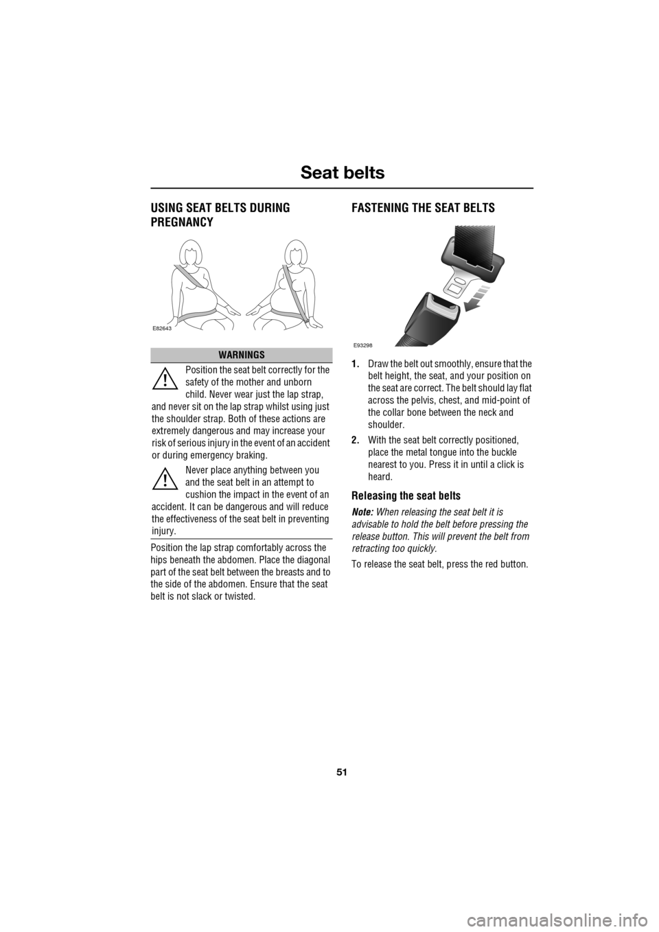
Position the lap strap comfortably across the
hips beneath the abdomen. Place the diagonal
part of the seat belt be tween the breasts and to
the side of the abdomen. Ensure that the seat
belt is not slack or twisted.
FASTENING THE SEAT BELTS
1. Draw the belt out smoothly, ensure that the
belt height, the seat , and your position on
the seat are correct. The belt should lay flat
across the pelvis, ches t, and mid-point of
the collar bone between the neck and
shoulder.
2. With the seat belt correctly positioned,
place the metal tongue into the buckle
nearest to you. Press it in until a click is
heard.
Releasing the seat belts
Note: When releasing the seat belt it is
advisable to hold the belt before pressing the
release button. This will prevent the belt from
retracting too quickly.
To release the seat belt, press the red button.
WARNINGS
Position the seat belt correctly for the
safety of the mother and unborn
child. Never wear just the lap strap,
and never sit on the lap strap whilst using just
the shoulder strap. Both of these actions are
extremely dangerous a nd may increase your
risk of serious injury in the event of an accident
or during emergency braking.
Never place anything between you
and the seat belt in an attempt to
cushion the impact in the event of an
accident. It can be da ngerous and will reduce
the effectiveness of the seat belt in preventing
injury.
E82643
E93298
Page 52 of 391

Seat belts
52
SEAT BELT HEIGHT ADJUSTMENT
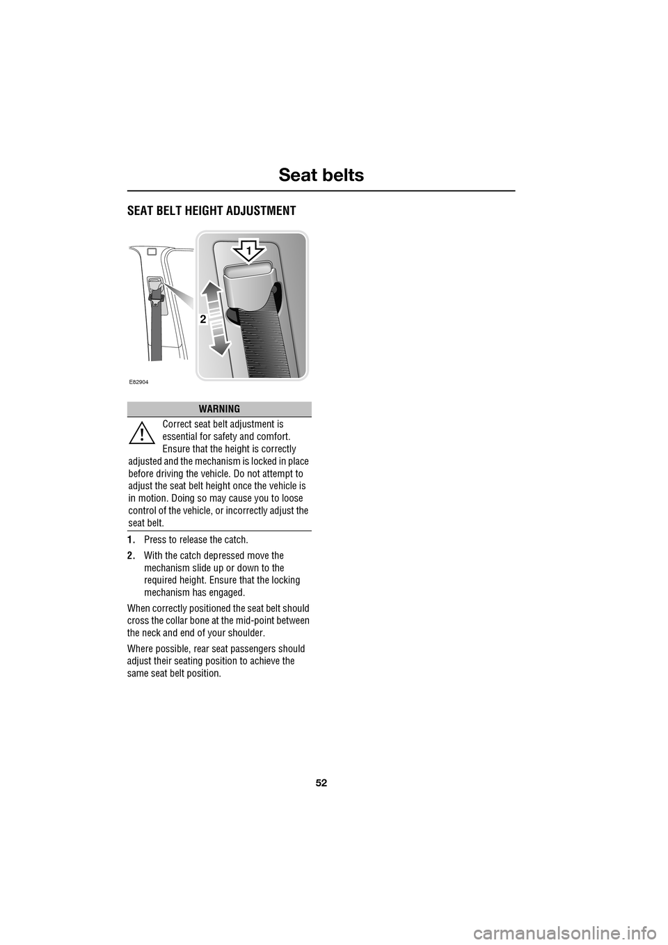
1.Press to release the catch.
2. With the catch depressed move the
mechanism slide up or down to the
required height. Ensure that the locking
mechanism has engaged.
When correctly positione d the seat belt should
cross the collar bone at the mid-point between
the neck and end of your shoulder.
Where possible, rear seat passengers should
adjust their seating pos ition to achieve the
same seat belt position.
WARNING
Correct seat belt adjustment is
essential for safety and comfort.
Ensure that the height is correctly
adjusted and the mechanism is locked in place
before driving the vehicl e. Do not attempt to
adjust the seat belt height once the vehicle is
in motion. Doing so may cause you to loose
control of the vehicle, or incorrectly adjust the
seat belt.
E82904
2
1
Page 216 of 391

Wheels and tyres
216
GENERAL INFORMATION
Tyre markings
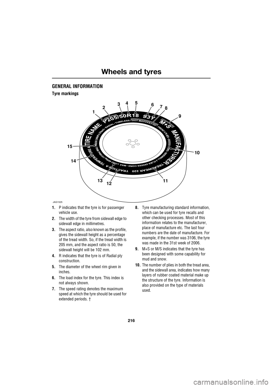
1.P indicates that the tyre is for passenger
vehicle use.
2. The width of the tyre fr om sidewall edge to
sidewall edge in millimetres.
3. The aspect ratio, also known as the profile,
gives the sidewall height as a percentage
of the tread width. So, if the tread width is
205 mm, and the aspect ratio is 50, the
sidewall height will be 102 mm.
4. R indicates that the ty re is of Radial ply
construction.
5. The diameter of the wheel rim given in
inches.
6. The load index for the tyre. This index is
not always shown.
7. The speed rating denotes the maximum
speed at which the tyre should be used for
extended periods. † 8.
Tyre manufacturing standard information,
which can be used for tyre recalls and
other checking processe s. Most of this
information relates to the manufacturer,
place of manufacture etc. The last four
numbers are the date of manufacture. For
example, if the number was 3106, the tyre
was made in the 31st week of 2006.
9. M+S or M/S indicates that the tyre has
been designed with some capability for
mud and snow.
10. The number of plies in both the tread area,
and the sidewall area, indicates how many
layers of rubber coat ed material make up
the structure of the tyre. Information is
also provided on the type of materials
used.
JAG1525
12345678
9
10
111213
14
15
Page 219 of 391

219
Wheels and tyres
The following procedure should be used to
check and adjust the tyres pressures.
1.Remove the valve cap.
2. Firmly attach a tyre pressure gauge/inflator
to the valve.
3. Read the tyre pressure from the gauge,
and add air if required.
4. If air is added to the tyre, remove the gauge
and re-attach it be fore reading the
pressure. Failure to do so may result in an
inaccurate reading.
5. If the tyre pressure is too high, remove the
gauge and allow air out of the tyre by
pressing the centre of the valve. Refit the
gauge to the valve and check the pressure.
6. Repeat the process a dding or removing air
as required until the correct tyre pressure
is reached.
7. Refit the valve cap.
Note: It is an offence in certain countries to
drive a vehicle with incorrect tyre pressures.
Note: It is the driver's responsibility to ensure
that the tyre pressures are correct.
Tyre valves
Keep the valve caps screwed down firmly to
prevent water or dirt entering the valve. Check
the valves for leaks when checking the tyre
pressures.
Pressure compensation for ambient
temperature changes
If the intended journey will take the vehicle into
an area where the ambien t local temperature is
known to be lower than the journey start point,
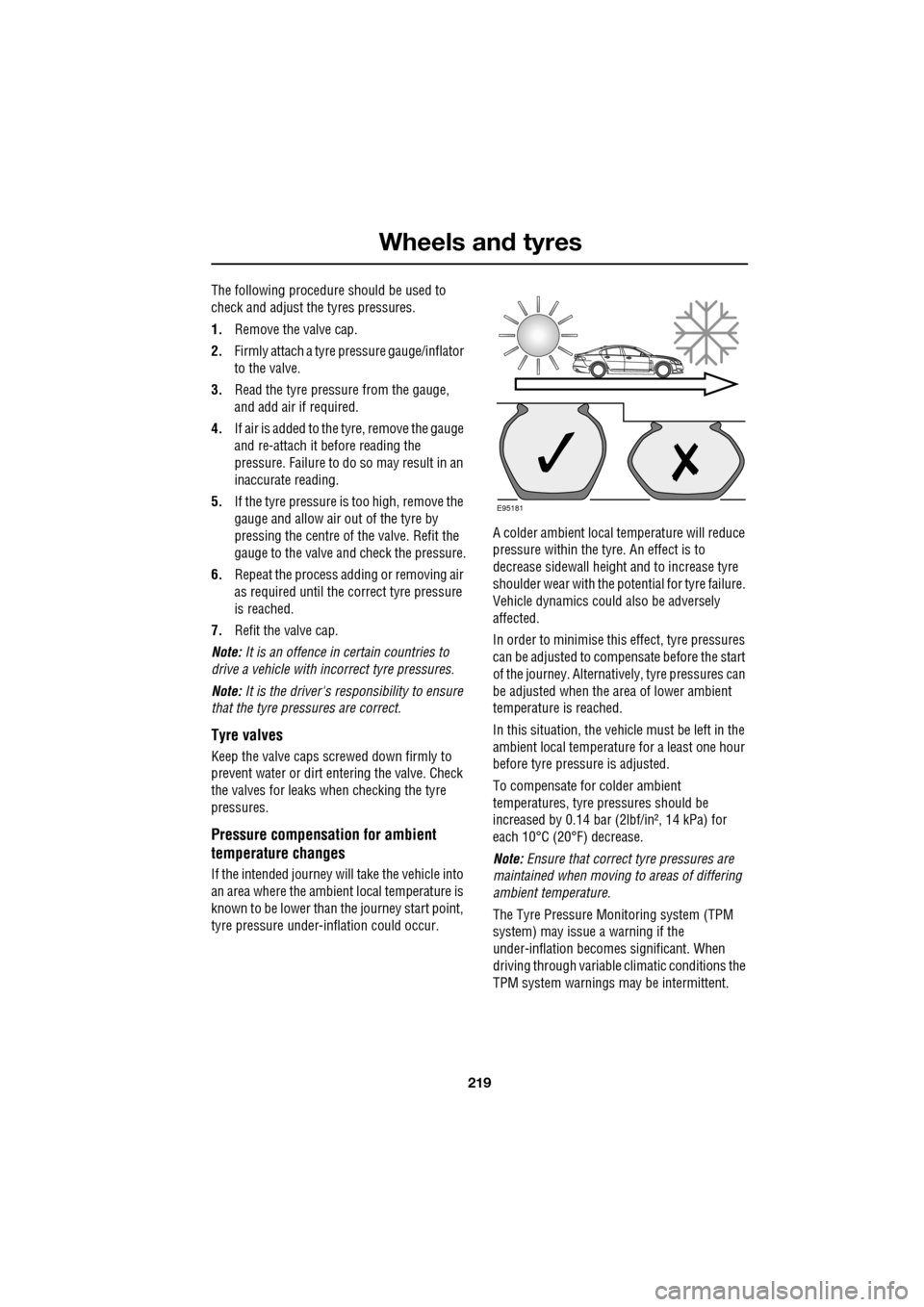
tyre pressure under-i nflation could occur. A colder ambient local temperature will reduce
pressure within the tyre. An effect is to
decrease sidewall height
and to increase tyre
shoulder wear with the potential for tyre failure.
Vehicle dynamics could also be adversely
affected.
In order to minimise this effect, tyre pressures
can be adjusted to compensate before the start
of the journey. Alternatively, tyre pressures can
be adjusted when the area of lower ambient
temperature is reached.
In this situation, the vehicle must be left in the
ambient local temperature for a least one hour
before tyre pressu re is adjusted.
To compensate for colder ambient
temperatures, tyre pressures should be
increased by 0.14 bar (2lbf/in², 14 kPa) for
each 10°C (20°F) decrease.
Note: Ensure that correct tyre pressures are
maintained when moving to areas of differing
ambient temperature.
The Tyre Pressure M onitoring system (TPM
system) may issue a warning if the
under-inflation becomes significant. When
driving through variable climatic conditions the
TPM system warnings may be intermittent.
E95181
Page 260 of 391

Technical specifications
260
DIMENSIONS
¹ Narrowest dimension applies to 20 inch wheels only.
E95307
1
2
3
4
5
6
7
Item Description mm/inches
1 Width 2053/80.5
2 Width with mirrors folded 1877/74.0
3 Track - front 1559/61.4
4 Maximum height 1460/57.5
5 Track - rear¹ 1571-1605/61.9-63.2
6 Wheelbase 2909/114.5
7 Length excluding numbe r plate plinth 4961/195.3
- Turning circle (kerb to kerb)11.5 m/37.7 ft.
Page 380 of 391

Navigation system
380
THE DISCLAIMER OF WARRANTY AND
LIMITATION OF LIABILITY, SET FORTH IN
THIS AGREEMENT, DO NOT AFFECT OR
PREJUDICE YOUR STATUTORY RIGHTS
WHERE YOU HAVE ACQUIRED THE
DATABASE OTHERWISE THAN IN THE
COURSE OF A BUSINESS. Some states and
laws do not allow the exclusion of implied
warranties, so the abov e disclaimer may not
apply to you.
Government end users
If the DATABASE is for a region of North
America and is being acqui red by or on behalf
of the United States government or any other
entity seeking or applyi ng rights similar to
those customarily claimed by the United States
government, the DATABASE is licensed with
‘limited rights’. Utilization of the DATA
BASE is subject to the
restrictions specified in the ‘Rights in Technical
Data and Computer Database’ clause at DFARS
252.227–7013, or the equivalent clause for
non-defence agencies. Manufacturer of the
DATABASE of North America is NAVTEQ
Corporation, 10400 W. Higgins Road, Suite
400, Rosemont, Illinois 60018, USA.
EUROPEAN DECLARATION OF
CONFORMITY
Hereby, DENSO CORPORATION
declares that this DN-NS-019 is in
compliance with the essential
requirements and other relevant
provisions of Directive 1999/5/EC.WARNING
The DATABASE reflects reality as
existing before you received the
DATABASE and it comprises data and
information from government and other
sources, which may contain errors and
omissions. Accordingly, the DATABASE may
contain inaccurate or incomplete information
due to the passage of time, changing
circumstances, and due to the nature of the
sources used. The DATABASE does not
include or reflect inform ation on - inter alia -
neighbourhood safety; law enforcement;
emergency assistance; construction work;
road or lane closures; vehicle or speed
restrictions; road slope or grade; bridge
height, weight or other limits; road or traffic
conditions; special even ts; traffic congestion;
or travel time.