2009 INFINITI QX56 height
[x] Cancel search: heightPage 3158 of 4171
RSU-10
< ON-VEHICLE REPAIR >
REAR SUSPENSION ASSEMBLY
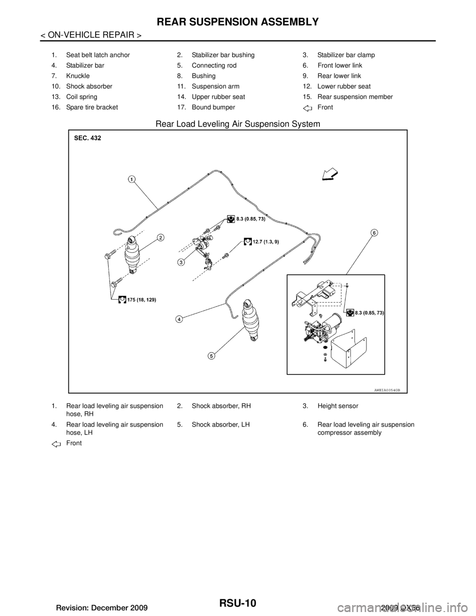
Rear Load Leveling Air Suspension System
1. Seat belt latch anchor 2. Stabilizer bar bushing 3. Stabilizer bar clamp
4. Stabilizer bar 5. Connecting rod 6. Front lower link
7. Knuckle 8. Bushing 9. Rear lower link
10. Shock absorber 11. Suspension arm 12. Lower rubber seat
13. Coil spring 14. Upper rubber seat 15. Rear suspension member
16. Spare tire bracket 17. Bound bumper Front
AWEIA0054GB
1. Rear load leveling air suspension hose, RH 2. Shock absorber, RH 3. Height sensor
4. Rear load leveling air suspension hose, LH 5. Shock absorber, LH 6. Rear load leveling air suspension
compressor assembly
Front
Revision: December 20092009 QX56
Page 3160 of 4171

RSU-12
< REMOVAL AND INSTALLATION >
REAR SUSPENSION MEMBER
Rear Load Leveling Air Suspension System
REMOVAL
1. If equipped with rear load leveling air suspension system, use CONSULT-III “EXHAUST SOLENOID”
active test to release the air pressure from the rear load leveling air suspension system.
2. If equipped with the rear load leveling air suspension system, disconnect the electrical connectors for the
height sensor and the rear load leveling air suspension compressor assembly.
3. If equipped with the rear load leveling air suspension system, unclip the rubber cover to access the rear
load leveling air suspension compressor assembly.
1. Seat belt latch anchor 2. Stabilizer bar bushing 3. Stabilizer bar clamp
4. Stabilizer bar 5. Connecting rod 6. Front lower link
7. Knuckle 8. Bushing 9. Rear lower link
10. Shock absorber 11. Suspension arm 12. Lower rubber seat
13. Coil spring 14. Upper rubber seat 15. Rear suspension member
16. Spare tire bracket 17. Bound bumper Front
AWEIA0054GB
1. Rear load leveling air suspension
hose, RH 2. Shock absorber, RH 3. Height sensor
4. Rear load leveling air suspension hose, LH 5. Shock absorber, LH 6. Rear load leveling air suspension
compressor assembly (includes the
bracket and rubber cover)
Front
Revision: December 20092009 QX56
Page 3161 of 4171
REAR SUSPENSION MEMBERRSU-13
< REMOVAL AND INSTALLATION >
C
DF
G H
I
J
K L
M A
B
RSU
N
O P
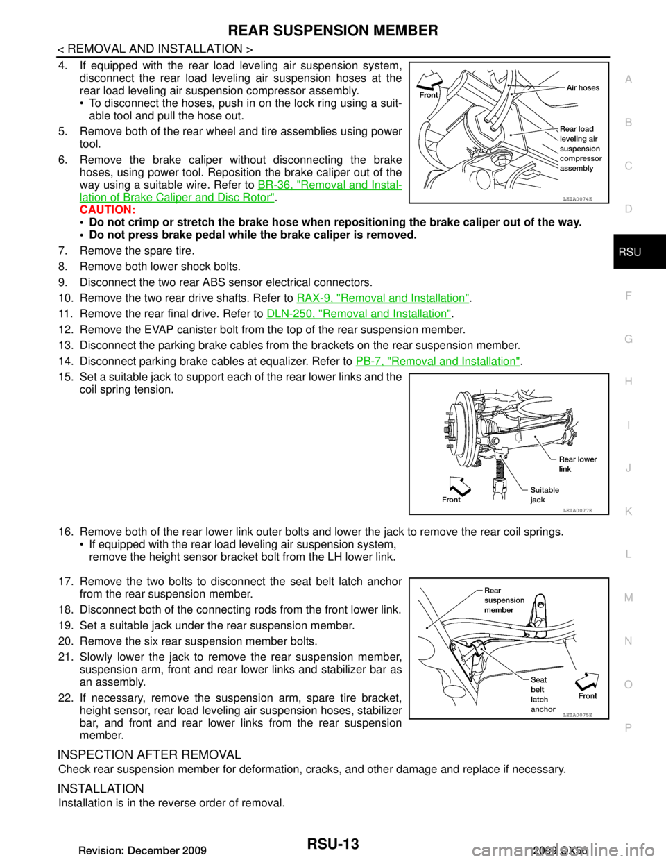
4. If equipped with the rear load leveling air suspension system, disconnect the rear load leveling air suspension hoses at the
rear load leveling air suspension compressor assembly.
To disconnect the hoses, push in on the lock ring using a suit-
able tool and pull the hose out.
5. Remove both of the rear wheel and tire assemblies using power tool.
6. Remove the brake caliper without disconnecting the brake hoses, using power tool. Reposition the brake caliper out of the
way using a suitable wire. Refer to BR-36, "Removal and Instal-
lation of Brake Caliper and Disc Rotor".
CAUTION:
Do not crimp or stretch the brake hose when re positioning the brake caliper out of the way.
Do not press brake pedal while the brake caliper is removed.
7. Remove the spare tire.
8. Remove both lower shock bolts.
9. Disconnect the two rear ABS sensor electrical connectors.
10. Remove the two rear drive shafts. Refer to RAX-9, "Removal and Installation"
.
11. Remove the rear final drive. Refer to DLN-250, "Removal and Installation"
.
12. Remove the EVAP canister bolt from the top of the rear suspension member.
13. Disconnect the parking brake cables from t he brackets on the rear suspension member.
14. Disconnect parking brake cables at equalizer. Refer to PB-7, "Removal and Installation"
.
15. Set a suitable jack to support each of the rear lower links and the coil spring tension.
16. Remove both of the rear lower link outer bolts and lower the jack to remove the rear coil springs. If equipped with the rear load leveling air suspension system,
remove the height sensor bracket bolt from the LH lower link.
17. Remove the two bolts to disconnect the seat belt latch anchor from the rear suspension member.
18. Disconnect both of the connecting r ods from the front lower link.
19. Set a suitable jack under the rear suspension member.
20. Remove the six rear suspension member bolts.
21. Slowly lower the jack to remove the rear suspension member, suspension arm, front and rear lower links and stabilizer bar as
an assembly.
22. If necessary, remove the suspension arm, spare tire bracket, height sensor, rear load leveling air suspension hoses, stabilizer
bar, and front and rear lower links from the rear suspension
member.
INSPECTION AFTER REMOVAL
Check rear suspension member for deformation, cracks, and other damage and replace if necessary.
INSTALLATION
Installation is in the reverse order of removal.
LEIA0074E
LEIA0077E
LEIA0075E
Revision: December 20092009 QX56
Page 3163 of 4171
SHOCK ABSORBERRSU-15
< REMOVAL AND INSTALLATION >
C
DF
G H
I
J
K L
M A
B
RSU
N
O P
SHOCK ABSORBER
Removal and InstallationINFOID:0000000005889873
REMOVAL
1. Remove the wheel and tire assembly using power tool. Refer to WT-41, "Adjustment".
2. If equipped with the rear load leveling air suspens ion system, use CONSULT-III "EXHAUST SOLENOID"
active test to release the air pressure from the rear load leveling air suspension system.
3. Disconnect the height sensor electrical connector.
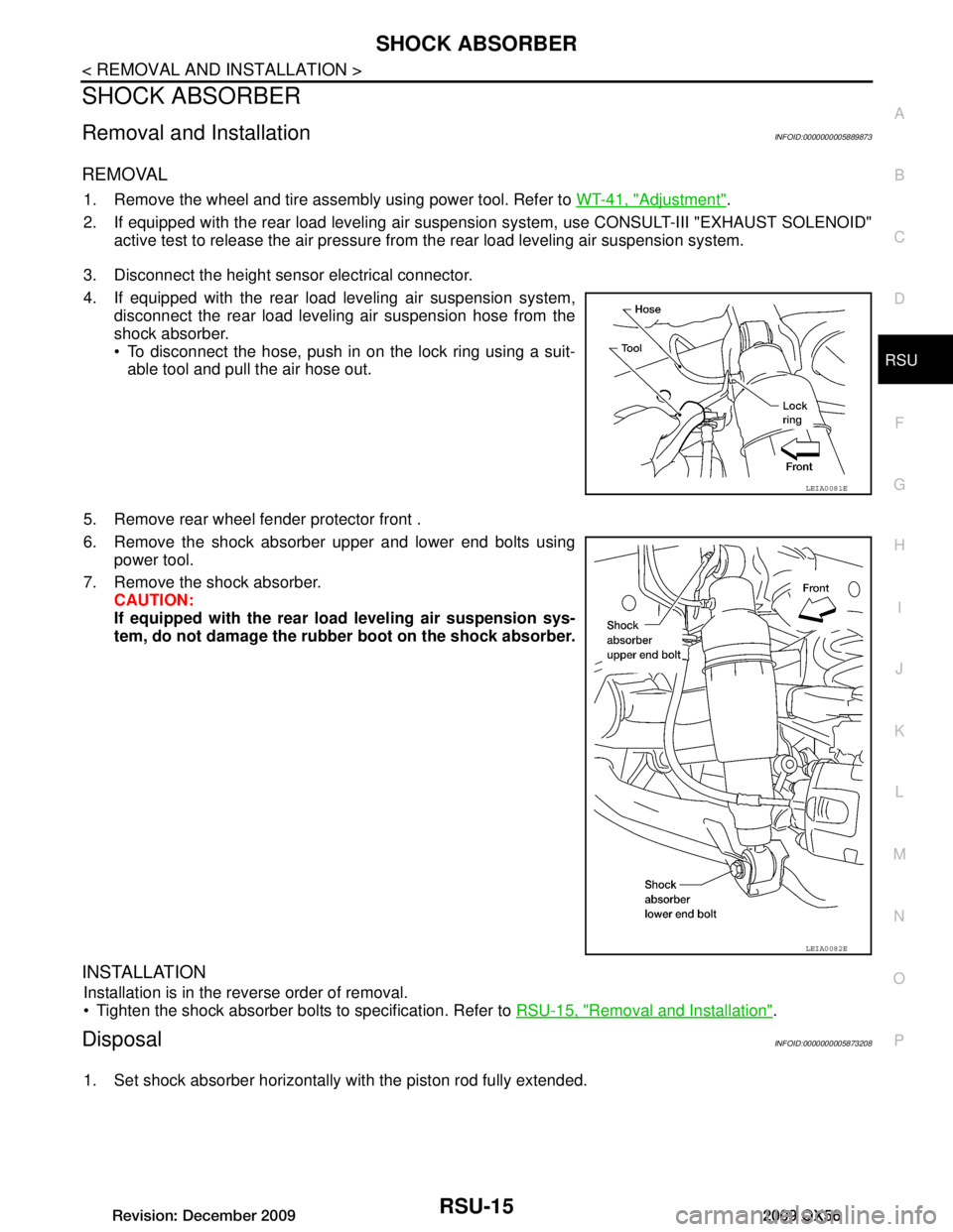
4. If equipped with the rear load leveling air suspension system, disconnect the rear load leveling air suspension hose from the
shock absorber.
To disconnect the hose, push in on the lock ring using a suit-able tool and pull the air hose out.
5. Remove rear wheel fender protector front .
6. Remove the shock absorber upper and lower end bolts using power tool.
7. Remove the shock absorber. CAUTION:
If equipped with the rear lo ad leveling air suspension sys-
tem, do not damage the rubber boot on the shock absorber.
INSTALLATION
Installation is in the reverse order of removal.
Tighten the shock absorber bolts to specification. Refer to RSU-15, "Removal and Installation"
.
DisposalINFOID:0000000005873208
1. Set shock absorber horizontally with the piston rod fully extended.
LEIA0081E
LEIA0082E
Revision: December 20092009 QX56
Page 3165 of 4171
SUSPENSION ARMRSU-17
< REMOVAL AND INSTALLATION >
C
DF
G H
I
J
K L
M A
B
RSU
N
O P
SUSPENSION ARM
Removal and InstallationINFOID:0000000005889874
REMOVAL
1. If equipped with rear load leveling air suspension system, use CONSULT-III “EXHAUST SOLENOID”
active test to release the air pressure from the rear load leveling air suspension system.
2. If equipped with the rear load leveling air suspension system, disconnect the electrical connectors for the
height sensor and the rear load leveling air suspension compressor assembly.
3. If equipped with the rear load leveling air suspension system, unclip the rubber cover to access the rear
load leveling air suspension compressor assembly.
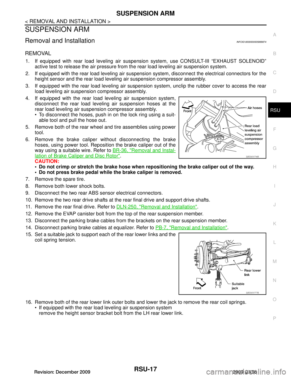
4. If equipped with the rear load leveling air suspension system, disconnect the rear load leveling air suspension hoses at the
rear load leveling air suspension compressor assembly.
To disconnect the hoses, push in on the lock ring using a suit-able tool and pull the hose out.
5. Remove both of the rear wheel and tire assemblies using power tool.
6. Remove the brake caliper without disconnecting the brake hoses, using power tool. Reposition the brake caliper out of the
way using a suitable wire. Refer to BR-36, "Removal and Instal-
lation of Brake Caliper and Disc Rotor".
CAUTION:
Do not crimp or stretch the brake hose when re positioning the brake caliper out of the way.
Do not press brake pedal while the brake caliper is removed.
7. Remove the spare tire.
8. Remove both lower shock bolts.
9. Disconnect the two rear ABS sensor electrical connectors.
10. Remove the two rear drive shafts at t he rear final drive and support drive shafts.
11. Remove the rear final drive. Refer to DLN-250, "Removal and Installation"
.
12. Remove the EVAP canister bolt from the top of the rear suspension member.
13. Disconnect the parking brake cables from t he brackets on the rear suspension member.
14. Disconnect parking brake cables at equalizer. Refer to PB-7, "Removal and Installation"
.
15. Set a suitable jack to support each of the rear lower links and the coil spring tension.
16. Remove both of the rear lower link outer bolts and lower the jack to remove the rear coil springs. If equipped with the rear load leveling air suspension systemremove the height sensor bracket bolt from the LH rear lower link.
LEIA0074E
LEIA0077E
Revision: December 20092009 QX56
Page 3169 of 4171
REAR LOWER LINK & COIL SPRINGRSU-21
< REMOVAL AND INSTALLATION >
C
DF
G H
I
J
K L
M A
B
RSU
N
O P
REAR LOWER LINK & COIL SPRING
Removal and InstallationINFOID:0000000005889876
REMOVAL
1. Remove the wheel and tire assembly using power tool. Refer to WT-41, "Adjustment".
2. If equipped with rear load leveling air suspension system, use CONSULT-III “EXHAUST SOLENOID”
active test to release the air pressure from the rear load leveling air suspension system.
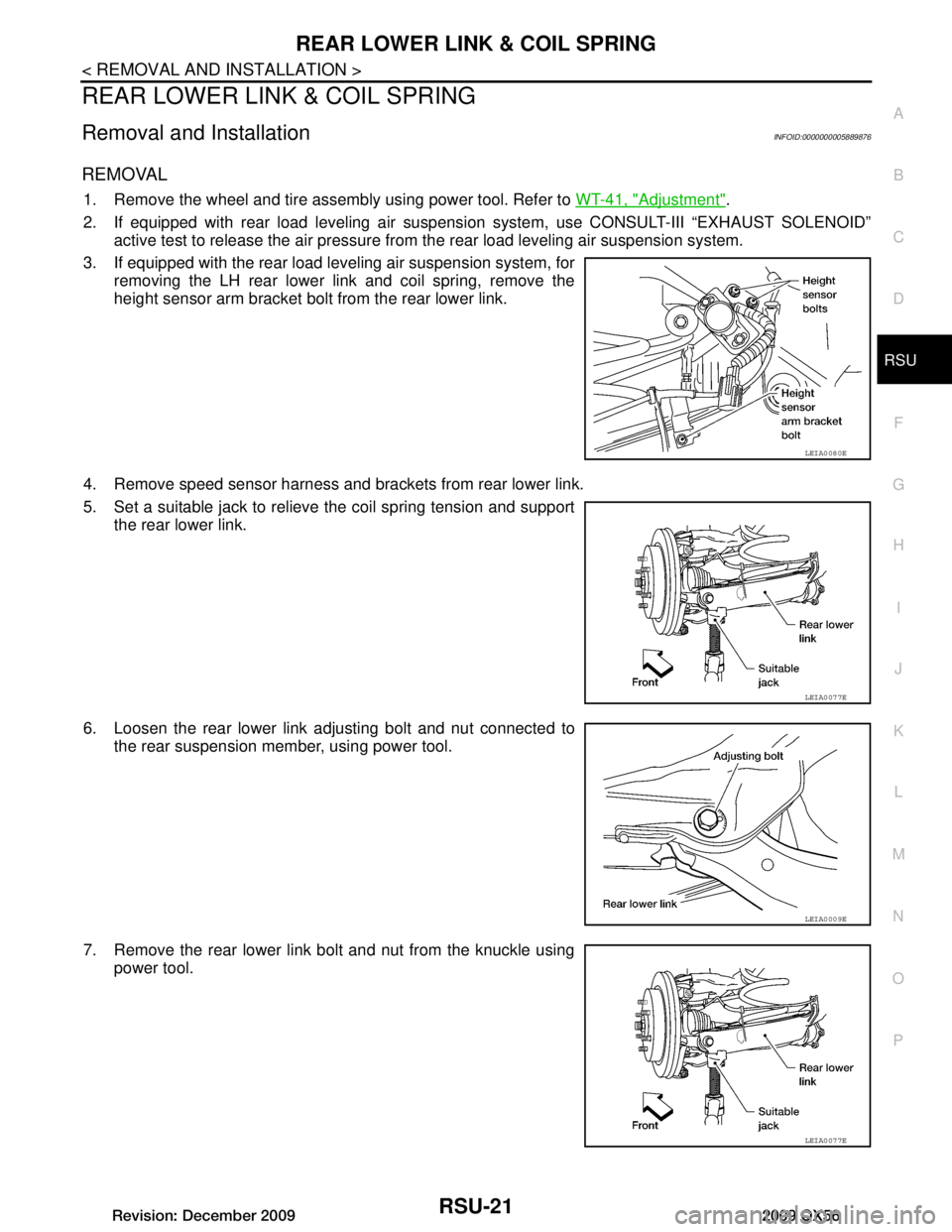
3. If equipped with the rear load leveling air suspension system, for removing the LH rear lower link and coil spring, remove the
height sensor arm bracket bolt from the rear lower link.
4. Remove speed sensor harness and brackets from rear lower link.
5. Set a suitable jack to relieve the coil spring tension and support the rear lower link.
6. Loosen the rear lower link adjusting bolt and nut connected to the rear suspension member, using power tool.
7. Remove the rear lower link bolt and nut from the knuckle using power tool.
LEIA0080E
LEIA0077E
LEIA0009E
LEIA0077E
Revision: December 20092009 QX56
Page 3172 of 4171
RSU-24
< REMOVAL AND INSTALLATION >
REAR LOAD LEVELING AIR SUSPENSION COMPRESSOR ASSEMBLY
REAR LOAD LEVELING AIR SUSPENSION COMPRESSOR ASSEMBLY
Removal and InstallationINFOID:0000000003772299
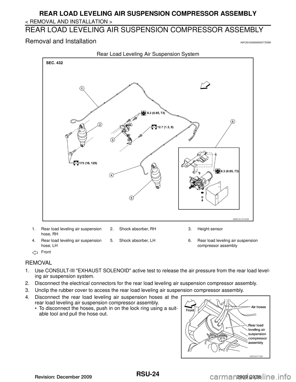
Rear Load Leveling Air Suspension System
REMOVAL
1. Use CONSULT-III "EXHAUST SOLENOID" active test to release the air pressure from the rear load level-
ing air suspension system.
2. Disconnect the electrical connectors for the rear load leveling air suspension compressor assembly.
3. Unclip the rubber cover to access the rear load leveling air suspension compressor assembly.
4. Disconnect the rear load leveling air suspension hoses at the rear load leveling air suspension compressor assembly.
To disconnect the hoses, push in on the lock ring using a suit-
able tool and pull the hose out.
AWEIA0054GB
1. Rear load leveling air suspension
hose, RH 2. Shock absorber, RH 3. Height sensor
4. Rear load leveling air suspension hose, LH 5. Shock absorber, LH 6. Rear load leveling air suspension
compressor assembly
Front
LEIA0074E
Revision: December 20092009 QX56
Page 3174 of 4171
RSU-26
< REMOVAL AND INSTALLATION >
CONTROL UNIT
CONTROL UNIT
Removal and InstallationINFOID:0000000003772300
REMOVAL
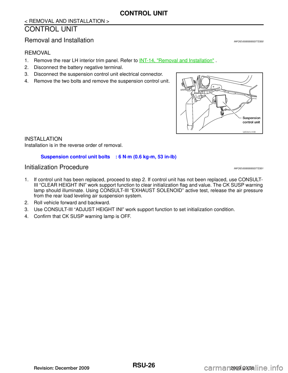
1. Remove the rear LH interior trim panel. Refer to INT-14, "Removal and Installation" .
2. Disconnect the battery negative terminal.
3. Disconnect the suspension control unit electrical connector.
4. Remove the two bolts and remove the suspension control unit.
INSTALLATION
Installation is in the reverse order of removal.
Initialization ProcedureINFOID:0000000003772301
1. If control unit has been replaced, proceed to step 2. If control unit has not been replaced, use CONSULT-
III “CLEAR HEIGHT INI” work support function to clear initialization flag and value. The CK SUSP warning
lamp should illuminate. Using CONSULT-III “EXHAUST SOLENOID” active test, release the air pressure
from the rear load leveling air suspension system.
2. Roll vehicle forward and backward.
3. Use CONSULT-III “ADJUST HEIGHT INI” work support function to set initialization condition.
4. Confirm that CK SUSP warning lamp is OFF.
LEIA0100E
Suspension control unit bolts : 6 N·m (0.6 kg-m, 53 in-lb)
Revision: December 20092009 QX56