2009 INFINITI QX56 ESP
[x] Cancel search: ESPPage 1795 of 4171
![INFINITI QX56 2009 Factory Service Manual
EC-468
< ECU DIAGNOSIS >[VK56DE]
ECM
ItemOBD-
MID Self-diagnostic test item DTC Test value and Test
limit
(GST display) Description
TID Unit and
Scaling ID
HO2S 01H
Air fuel ratio (A/F) sensor 1
INFINITI QX56 2009 Factory Service Manual
EC-468
< ECU DIAGNOSIS >[VK56DE]
ECM
ItemOBD-
MID Self-diagnostic test item DTC Test value and Test
limit
(GST display) Description
TID Unit and
Scaling ID
HO2S 01H
Air fuel ratio (A/F) sensor 1](/manual-img/42/57031/w960_57031-1794.png)
EC-468
< ECU DIAGNOSIS >[VK56DE]
ECM
ItemOBD-
MID Self-diagnostic test item DTC Test value and Test
limit
(GST display) Description
TID Unit and
Scaling ID
HO2S 01H
Air fuel ratio (A/F) sensor 1
(Bank 1) P0131 83H 0BH
Minimum sensor output voltage for test
cycle
P0131 84H 0BH Maximum sensor output voltage for test
cycle
P0130 85H 0BH Minimum sensor output voltage for test
cycle
P0130 86H 0BH Maximum sensor output voltage for test
cycle
P0133 87H 04H Response rate: Response ratio (Lean to
Rich)
P0133 88H 04H Response rate: Response ratio (Rich to
Lean)
P2A00 89H 84H The amount of shift in air fuel ratio
P2A00 8AH 84H The amount of shift in air fuel ratio P0130 8BH 0BH Difference in sensor output voltage
P0133 8CH 83H Response gain at the limited frequency
02H Heated oxygen sensor 2
(Bank 1) P0138 07H 0CH
Minimum sensor output voltage for test
cycle
P0137 08H 0CH Maximum sensor output voltage for test
cycle
P0138 80H 0CH Sensor output voltage
P0139 81H 0CH Difference in sensor output voltage
03H Heated oxygen sensor 3
(Bank 1) P0143 07H 0CH
Minimum sensor output voltage for test
cycle
P0144 08H 0CH Maximum sensor output voltage for test
cycle
P0146 80H 0CH Sensor output voltage
P0145 81H 0CH Difference in sensor output voltage
Revision: December 20092009 QX56
Page 1796 of 4171
![INFINITI QX56 2009 Factory Service Manual
ECM
EC-469
< ECU DIAGNOSIS > [VK56DE]
C
D
E
F
G H
I
J
K L
M A
EC
NP
O
HO2S 05H
Air fuel ratio (A/F) sensor 1
(Bank 2) P0151 83H 0BH
Minimum sensor output voltage for test
cycle
P0151 84H 0BH Maximu INFINITI QX56 2009 Factory Service Manual
ECM
EC-469
< ECU DIAGNOSIS > [VK56DE]
C
D
E
F
G H
I
J
K L
M A
EC
NP
O
HO2S 05H
Air fuel ratio (A/F) sensor 1
(Bank 2) P0151 83H 0BH
Minimum sensor output voltage for test
cycle
P0151 84H 0BH Maximu](/manual-img/42/57031/w960_57031-1795.png)
ECM
EC-469
< ECU DIAGNOSIS > [VK56DE]
C
D
E
F
G H
I
J
K L
M A
EC
NP
O
HO2S 05H
Air fuel ratio (A/F) sensor 1
(Bank 2) P0151 83H 0BH
Minimum sensor output voltage for test
cycle
P0151 84H 0BH Maximum sensor output voltage for test
cycle
P0150 85H 0BH Minimum sensor output voltage for test
cycle
P0150 86H 0BH Maximum sensor output voltage for test
cycle
P0153 87H 04H Response rate: Response ratio (Lean to
Rich)
P0153 88H 04H Response rate: Response ratio (Rich to
Lean)
P2A03 89H 84H The amount of shift in air fuel ratio
P2A03 8AH 84H The amount of shift in air fuel ratio P0150 8BH 0BH Difference in sensor output voltage
P0153 8CH 83H Response gain at the limited frequency
06H Heated oxygen sensor 2
(Bank 2) P0158 07H 0CH
Minimum sensor output voltage for test
cycle
P0157 08H 0CH Maximum sensor output voltage for test
cycle
P0158 80H 0CH Sensor output voltage
P0159 81H 0CH Difference in sensor output voltage
07H Heated oxygen sensor 3
(Bank2) P0163 07H 0CH
Minimum sensor output voltage for test
cycle
P0164 08H 0CH Maximum sensor output voltage for test
cycle
P0166 80H 0CH Sensor output voltage
P0165 81H 0CH Difference in sensor output voltage
CATA-
LY S T 21H
Three way catalyst function
(Bank1) P0420 80H 01H O2 storage index
P0420 82H 01H
Switching time lag engine exhaust index
value
P2423 83H 0CH Difference in 3rd O2 sensor output volt-
age
P2423 84H 84H O2 storage index in HC trap catalyst
22H Three way catalyst function
(Bank2) P0430 80H 01H O2 storage index
P0430 82H 01H
Switching time lag engine exhaust index
value
P2424 83H 0CH Difference in 3rd O2 sensor output volt-
age
P2424 84H 84H O2 storage index in HC trap catalyst
Item
OBD-
MID Self-diagnostic test item DTC Test value and Test
limit
(GST display) Description
TID Unit and
Scaling ID
Revision: December 20092009 QX56
Page 1799 of 4171
![INFINITI QX56 2009 Factory Service Manual
EC-472
< ECU DIAGNOSIS >[VK56DE]
ECM
MISFIRE A1H Multiple Cylinder MisfiresP0301 80H 24H
Misfiring counter at 1000 revolution of
the first cylinder
P0302 81H 24H Misfiring counter at 1000 revolution INFINITI QX56 2009 Factory Service Manual
EC-472
< ECU DIAGNOSIS >[VK56DE]
ECM
MISFIRE A1H Multiple Cylinder MisfiresP0301 80H 24H
Misfiring counter at 1000 revolution of
the first cylinder
P0302 81H 24H Misfiring counter at 1000 revolution](/manual-img/42/57031/w960_57031-1798.png)
EC-472
< ECU DIAGNOSIS >[VK56DE]
ECM
MISFIRE A1H Multiple Cylinder MisfiresP0301 80H 24H
Misfiring counter at 1000 revolution of
the first cylinder
P0302 81H 24H Misfiring counter at 1000 revolution of
the second cylinder
P0303 82H 24H Misfiring counter at 1000 revolution of
the third cylinder
P0304 83H 24H Misfiring counter at 1000 revolution of
the fourth cylinder
P0305 84H 24H Misfiring counter at 1000 revolution of
the fifth cylinder
P0306 85H 24H Misfiring counter at 1000 revolution of
the sixth cylinder
P0307 86H 24H Misfiring counter at 1000 revolution of
the seventh cylinder
P0308 87H 24H Misfiring counter at 1000 revolution of
the eighth cylinder
P0300 88H 24H Misfiring counter at 1000 revolution of
the multiple cylinders
P0301 89H 24H Misfiring counter at 200 revolution of the
first cylinder
P0302 8AH 24H Misfiring counter at 200 revolution of the
second cylinder
P0303 8BH 24H Misfiring counter at 200 revolution of the
third cylinder
P0304 8CH 24H Misfiring counter at 200 revolution of the
fourth cylinder
P0305 8DH 24H Misfiring counter at 200 revolution of the
fifth cylinder
P0306 8EH 24H Misfiring counter at 200 revolution of the
sixth cylinder
P0307 8FH 24H Misfiring counter at 200 revolution of the
seventh cylinder
P0308 90H 24H Misfiring counter at 200 revolution of the
eighth cylinder
P0300 91H 24H Misfiring counter at 1000 revolution of
the single cylinder
P0300 92H 24H Misfiring counter at 200 revolution of the
single cylinder
P0300 93H 24H Misfiring counter at 200 revolution of the
multiple cylinders
Item
OBD-
MID Self-diagnostic test item DTC Test value and Test
limit
(GST display) Description
TID Unit and
Scaling ID
Revision: December 20092009 QX56
Page 1807 of 4171
![INFINITI QX56 2009 Factory Service Manual
EC-480
< PRECAUTION >[VK56DE]
PRECAUTIONS
PRECAUTION
PRECAUTIONS
Precaution for Supplemental Restraint S
ystem (SRS) "AIR BAG" and "SEAT BELT
PRE-TENSIONER"
INFOID:0000000005867525
The Supplemental INFINITI QX56 2009 Factory Service Manual
EC-480
< PRECAUTION >[VK56DE]
PRECAUTIONS
PRECAUTION
PRECAUTIONS
Precaution for Supplemental Restraint S
ystem (SRS) "AIR BAG" and "SEAT BELT
PRE-TENSIONER"
INFOID:0000000005867525
The Supplemental](/manual-img/42/57031/w960_57031-1806.png)
EC-480
< PRECAUTION >[VK56DE]
PRECAUTIONS
PRECAUTION
PRECAUTIONS
Precaution for Supplemental Restraint S
ystem (SRS) "AIR BAG" and "SEAT BELT
PRE-TENSIONER"
INFOID:0000000005867525
The Supplemental Restraint System such as “A IR BAG” and “SEAT BELT PRE-TENSIONER”, used along
with a front seat belt, helps to reduce the risk or severi ty of injury to the driver and front passenger for certain
types of collision. This system includes seat belt switch inputs and dual stage front air bag modules. The SRS
system uses the seat belt switches to determine the front air bag deployment, and may only deploy one front
air bag, depending on the severity of a collision and w hether the front occupants are belted or unbelted.
Information necessary to service the system safely is included in the SR and SB section of this Service Man-
ual.
WARNING:
To avoid rendering the SRS inopera tive, which could increase the risk of personal injury or death in
the event of a collision which would result in air bag inflation, all maintenance must be performed by
an authorized NISS AN/INFINITI dealer.
Improper maintenance, including in correct removal and installation of the SRS, can lead to personal
injury caused by unintent ional activation of the system. For re moval of Spiral Cable and Air Bag
Module, see the SR section.
Do not use electrical test equipmen t on any circuit related to the SRS unless instructed to in this
Service Manual. SRS wiring harnesses can be identi fied by yellow and/or orange harnesses or har-
ness connectors.
PRECAUTIONS WHEN USING POWER TOOLS (AIR OR ELECTRIC) AND HAMMERS
WARNING:
When working near the Airbag Diagnosis Sensor Unit or other Airbag System sensors with the Igni-
tion ON or engine running, DO NOT use air or electri c power tools or strike near the sensor(s) with a
hammer. Heavy vibration could activate the sensor( s) and deploy the air bag(s), possibly causing
serious injury.
When using air or electric power tools or hammers , always switch the Ignition OFF, disconnect the
battery, and wait at least 3 minu tes before performing any service.
On Board Diagnosis (OBD) System of Engine and A/TINFOID:0000000003771742
The ECM has an on board diagnostic system. It will light up the malfunction indicator lamp (MIL) to warn the
driver of a malfunction causing emission deterioration.
CAUTION:
Be sure to turn the ignition sw itch OFF and disconnect the negative battery cable before any repair
or inspection work. The open/short circuit of re lated switches, sensors, solenoid valves, etc. will
cause the MIL to light up.
Be sure to connect and lock the connectors secure ly after work. A loose (unlocked) connector will
cause the MIL to light up due to the open circuit. (Be sure the connector is free from water, grease,
dirt, bent terminals, etc.)
Certain systems and components, especially those related to OBD, may use a new style slide-lock-
ing type harness connector. For descrip tion and how to disconnect, refer to PG-68
.
Be sure to route and secure the harnesses properly after work. The interference of the harness with
a bracket, etc. may cause the MIL to li ght up due to the short circuit.
Be sure to connect rubber tubes properly afte r work. A misconnected or disconnected rubber tube
may cause the MIL to light up due to the malfunction of the EVAP system or fuel injection system,
etc.
Be sure to erase the unnecessary malfunction info rmation (repairs completed) from the ECM and
TCM (Transmission control module) before returning the vehicle to the customer.
Revision: December 20092009 QX56
Page 1846 of 4171

COMPRESSION PRESSUREEM-23
< ON-VEHICLE MAINTENANCE >
C
DE
F
G H
I
J
K L
M A
EM
NP
O
COMPRESSION PRESSURE
Checking Compression PressureINFOID:0000000005885870
1. Warm up the engine thoroughly. Then stop the engine.
2. Release the fuel pressure. Refer to EC-487, "
Fuel Pressure Check".
CAUTION:
If CONSULT-III is not used to release fuel pressure leave the fuel pump fuse disconnected until
step 7.
3. Remove the spark plug from each cylinder. Refer to EM-16, "
Removal and Installation".
4. Connect the engine tachometer (not required in use of CONSULT-III).
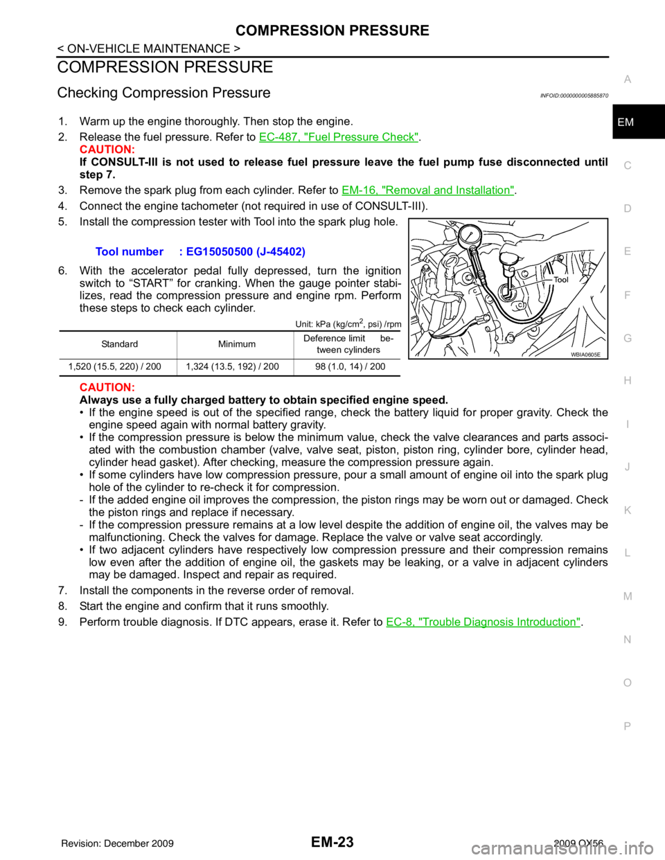
5. Install the compression tester with Tool into the spark plug hole.
6. With the accelerator pedal fully depressed, turn the ignition switch to “START” for cranking. When the gauge pointer stabi-
lizes, read the compression pressure and engine rpm. Perform
these steps to check each cylinder.
Unit: kPa (kg/cm2, psi) /rpm
CAUTION:
Always use a fully charged battery to obtain specified engine speed.
• If the engine speed is out of the specified range, check the battery liquid for proper gravity. Check the engine speed again with normal battery gravity.
• If the compression pressure is below the minimum value, check the valve clearances and parts associ-
ated with the combustion chamber (valve, valve seat , piston, piston ring, cylinder bore, cylinder head,
cylinder head gasket). After checking, measure the compression pressure again.
• If some cylinders have low compression pressure, pour a small amount of engine oil into the spark plug hole of the cylinder to re-check it for compression.
- If the added engine oil improves the compression, t he piston rings may be worn out or damaged. Check
the piston rings and replace if necessary.
- If the compression pressure remains at a low level despite the addition of engine oil, the valves may be malfunctioning. Check the valves for damage. Replace the valve or valve seat accordingly.
• If two adjacent cylinders have respectively low compression pressure and their compression remains low even after the addition of engine oil, the gaskets may be leaking, or a valve in adjacent cylinders
may be damaged. Inspect and repair as required.
7. Install the components in the reverse order of removal.
8. Start the engine and confirm that it runs smoothly.
9. Perform trouble diagnosis. If DTC appears, erase it. Refer to EC-8, "
Trouble Diagnosis Introduction".
Tool number : EG15050500 (J-45402)
Standard
MinimumDeference limit be-
tween cylinders
1,520 (15.5, 220) / 200 1,324 (13.5, 192) / 200 98 (1.0, 14) / 200WBIA0605E
Revision: December 20092009 QX56
Page 1871 of 4171

EM-48
< ON-VEHICLE REPAIR >
TIMING CHAIN
Check for cracks and any excessive wear at link plates. Replace
chain if necessary.
• In the same way as for the LH bank, inspect the timing chain andassociated parts on the RH bank.
INSTALLATION
NOTE:
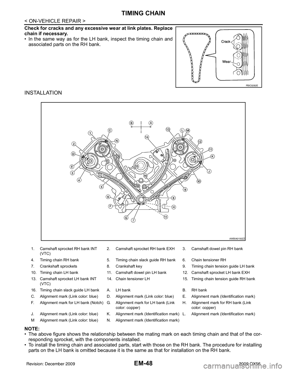
• The above figure shows the relationship between the ma ting mark on each timing chain and that of the cor-
responding sprocket, with the components installed.
• To install the timing chain and associated parts, start with those on the RH bank. The procedure for installing parts on the LH bank is omitted because it is t he same as that for installation on the RH bank.
PBIC0282E
1. Camshaft sprocket RH bank INT
(VTC) 2. Camshaft sprocket RH bank EXH 3. Camshaft dowel pin RH bank
4. Timing chain RH bank 5. Timing chain slack guide RH bank 6. Chain tensioner RH
7. Crankshaft sprockets 8. Crankshaft key9. Timing chain tension guide LH bank
10. Timing chain LH bank 11. Camshaft dowel pin LH bank 12. Camshaft sprocket LH bank EXH
13. Camshaft sprocket LH bank INT (VTC) 14. Chain tensioner LH
15. Timing chain tension guide RH bank
16. Timing chain slack guide LH bank A. LH bank B. RH bank
C. Alignment mark (Link color: blue) D. Alignment mark (Link color: blue) E. Alignment mark (Identification mark)
F. Alignment mark for LH bank (Notch) G. Alignment mark for LH bank (Link color: copper)H. Alignment mark
for RH bank (Link
color: copper)
J. Alignment mark (Link color: blue) K. Alignment mark (Identification mark) L. Alignment mark (Identification mark)
M Alignment mark (Link color: blue) N. Alignment mark (Identification mark)
AWBIA0150ZZ
Revision: December 20092009 QX56
Page 1875 of 4171

EM-52
< ON-VEHICLE REPAIR >
TIMING CHAIN
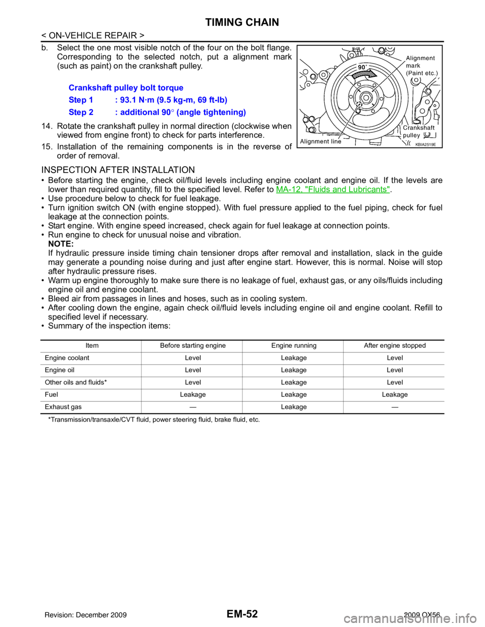
b. Select the one most visible notch of the four on the bolt flange.Corresponding to the selected notch, put a alignment mark
(such as paint) on the crankshaft pulley.
14. Rotate the crankshaft pulley in normal direction (clockwise when viewed from engine front) to check for parts interference.
15. Installation of the remaining components is in the reverse of order of removal.
INSPECTION AFTER INSTALLATION
• Before starting the engine, check oil/fluid levels in cluding engine coolant and engine oil. If the levels are
lower than required quantity, fill to the specified level. Refer to MA-12, "
Fluids and Lubricants".
• Use procedure below to check for fuel leakage.
• Turn ignition switch ON (with engine stopped). With fuel pressure applied to the fuel piping, check for fuel leakage at the connection points.
• Start engine. With engine speed increased, che ck again for fuel leakage at connection points.
• Run engine to check for unusual noise and vibration. NOTE:
If hydraulic pressure inside timing chain tensioner drops after removal and installation, slack in the guide
may generate a pounding noise during and just after engine start. However, this is normal. Noise will stop
after hydraulic pressure rises.
• Warm up engine thoroughly to make sure there is no leakage of fuel, exhaust gas, or any oils/fluids including engine oil and engine coolant.
• Bleed air from passages in lines and hoses, such as in cooling system.
• After cooling down the engine, again check oil/fluid levels including engine oil and engine coolant. Refill to
specified level if necessary.
• Summary of the inspection items:
*Transmission/transaxle/CVT fluid, power steering fluid, brake fluid, etc.
Crankshaft pulley bolt torque
Step 1 : 93.1 N·m (9.5 kg-m, 69 ft-lb)
Step 2 : additional 90 ° (angle tightening)
KBIA2519E
Item Before starting engine Engine runningAfter engine stopped
Engine coolant LevelLeakage Level
Engine oil LevelLeakage Level
Other oils and fluids* LevelLeakage Level
Fuel LeakageLeakageLeakage
Exhaust gas —Leakage —
Revision: December 20092009 QX56
Page 1890 of 4171

OIL SEALEM-67
< ON-VEHICLE REPAIR >
C
DE
F
G H
I
J
K L
M A
EM
NP
O
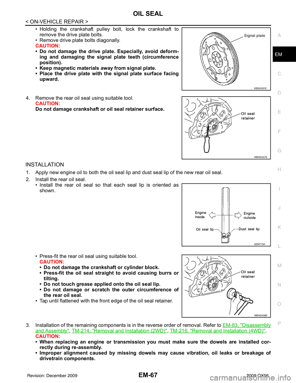
• Holding the crankshaft pulley bolt, lock the crankshaft to
remove the drive plate bolts.
• Remove drive plate bolts diagonally.
CAUTION:
• Do not damage the drive plate. Especially, avoid deform- ing and damaging the signal plate teeth (circumference
position).
• Keep magnetic materials away from signal plate.
• Place the drive plate with th e signal plate surface facing
upward.
4. Remove the rear oil seal using suitable tool. CAUTION:
Do not damage crankshaft or oil seal retainer surface.
INSTALLATION
1. Apply new engine oil to both the oil seal lip and dust seal lip of the new rear oil seal.
2. Install the rear oil seal.
• Install the rear oil seal so that each seal lip is oriented asshown.
• Press-fit the rear oil seal using suitable tool. CAUTION:
• Do not damage the crankshaft or cylinder block.
• Press-fit the oil seal straight to avoid causing burrs or
tilting.
• Do not touch grease applied onto the oil seal lip.
• Do not damage or scratch the outer circumference of
the rear oil seal.
• Tap until flattened with the front edge of the oil seal retainer.
3. Installation of the remaining components is in the reverse order of removal. Refer to EM-83, "
Disassembly
and Assembly", TM-214, "Removal and Installation (2WD)", TM-216, "Removal and Installation (4WD)".
CAUTION:
• When replacing an engine or transmission you must make sure the dowels are installed cor-
rectly during re-assembly.
• Improper alignment caused by missing dowels may cause vibration, oil leaks or breakage of
drivetrain components.
KBIA2491E
WBIA0437E
SEM715A
WBIA0438E
Revision: December 20092009 QX56