Page 2732 of 4171

MWI-10
< FUNCTION DIAGNOSIS >
METER SYSTEM
TACHOMETER : System Description
INFOID:0000000003776590
The tachometer indicates engine speed in revolutions per minute (rpm).
The ECM provides an engine speed signal to the co mbination meter via CAN communication lines.
TACHOMETER : Component Parts LocationINFOID:0000000003776591
TACHOMETER : Component DescriptionINFOID:0000000003776592
ENGINE COOLANT TEMPERATURE GAUGE
1. IPDM E/R E122, E1242. Combination meter M23, M24 3. Fuel level sensor unit and fuel pump
C5 (view with inspection hole cover re-
moved)
4. ECM E16 (view with battery removed) 5. ABS actuator and electric unit (control
unit) E125 6. Oil pressure switch F4
A: Oil pan (upper)
7. A/T assembly F9 8. BCM M18, M19 (view with instrument
lower panel LH removed)
AWNIA0201ZZ
Unit Description
Combination meter Indicates the engine speed in RPM according to the engine speed signal received from ECM via
CAN communication.
ECM Transmits the engine speed signal to the combination meter with CAN communication line.
Revision: December 20092009 QX56
Page 2733 of 4171
MWI
METER SYSTEMMWI-11
< FUNCTION DIAGNOSIS >
C
DE
F
G H
I
J
K L
M B A
O P
ENGINE COOLANT TEMPERATURE GAUGE : System DiagramINFOID:0000000003776593
ENGINE COOLANT TEMPERATURE GAUGE : System DescriptionINFOID:0000000003776594
The engine coolant temperature gauge indicates the engine coolant temperature.
The ECM provides an engine coolant temperature signal to the combination meter via CAN communication
lines.
ENGINE COOLANT TEMPERATURE GA UGE : Component Parts Location
INFOID:0000000003776595
SKIB6905E
1. IPDM E/R E122, E124 2. Combination meter M23, M24 3. Fuel level sensor unit and fuel pump
C5 (view with inspection hole cover re-
moved)
4. ECM E16 (view with battery removed) 5. ABS actuator and electric unit (control unit) E1256. Oil pressure switch F4
A: Oil pan (upper)
7. A/T assembly F9 8. BCM M18, M19 (view with instrument
lower panel LH removed)
AWNIA0201ZZ
Revision: December 20092009 QX56
Page 2735 of 4171

MWI
METER SYSTEMMWI-13
< FUNCTION DIAGNOSIS >
C
DE
F
G H
I
J
K L
M B A
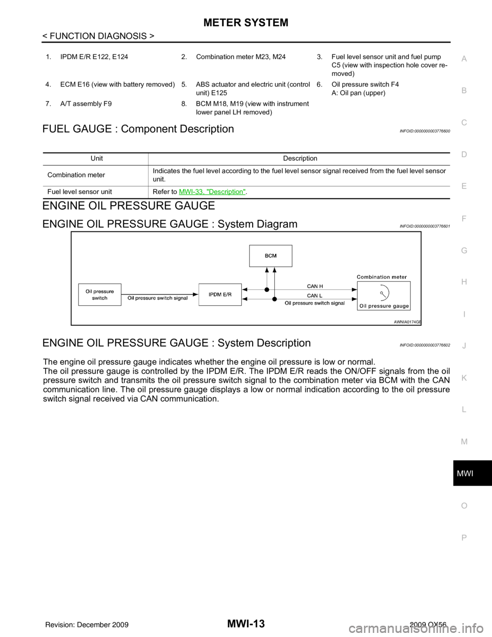
O PFUEL GAUGE : Component DescriptionINFOID:0000000003776600
ENGINE OIL PRESSURE GAUGE
ENGINE OIL PRESSURE GAUGE : System DiagramINFOID:0000000003776601
ENGINE OIL PRESSURE GAUGE : System DescriptionINFOID:0000000003776602
The engine oil pressure gauge indicates whether the engine oil pressure is low or normal.
The oil pressure gauge is controlled by the IPDM E/R. The IPDM E/R reads the ON /OFF signals from the oil
pressure switch and transmits the oil pressure switch signal to the combination meter via BCM with the CAN
communication line. The oil pressure gauge displays a low or normal indication according to the oil pressure
switch signal received via CAN communication.
1. IPDM E/R E122, E124 2. Combination meter M23, M24 3. Fuel level sensor unit and fuel pump
C5 (view with inspection hole cover re-
moved)
4. ECM E16 (view with battery removed) 5. ABS actuator and electric unit (control unit) E1256. Oil pressure switch F4
A: Oil pan (upper)
7. A/T assembly F9 8. BCM M18, M19 (view with instrument
lower panel LH removed)
Unit Description
Combination meter Indicates the fuel level according to the fuel level sensor signal received from the fuel level sensor
unit.
Fuel level sensor unit Refer to MWI-33, "
Description".
AWNIA0174GB
Revision: December 20092009 QX56
Page 2736 of 4171

MWI-14
< FUNCTION DIAGNOSIS >
METER SYSTEM
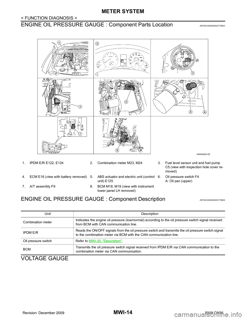
ENGINE OIL PRESSURE GAUGE : Component Parts Location
INFOID:0000000003776603
ENGINE OIL PRESSURE GAUGE : Component DescriptionINFOID:0000000003776604
VOLTAGE GAUGE
1. IPDM E/R E122, E124 2. Combination meter M23, M24 3. Fuel level sensor unit and fuel pump
C5 (view with inspection hole cover re-
moved)
4. ECM E16 (view with battery removed) 5. ABS actuator and electric unit (control
unit) E125 6. Oil pressure switch F4
A: Oil pan (upper)
7. A/T assembly F9 8. BCM M18, M19 (view with instrument
lower panel LH removed)
AWNIA0201ZZ
Unit Description
Combination meter Indicates the engine oil pressure (low/normal) according to the oil pressure switch signal received
from BCM with CAN
communication line.
IPDM E/R Reads the ON/OFF signals from the oil pressure switch and transmits the oil pressure switch signal
to the combination meter via BCM with the CAN communication line.
Oil pressure switch Refer to MWI-35, "
Description".
BCM Transmits the oil pressure switch signal received from IPDM E/R via CAN communication to the
combination meter via CAN communication.
Revision: December 20092009 QX56
Page 2737 of 4171
MWI
METER SYSTEMMWI-15
< FUNCTION DIAGNOSIS >
C
DE
F
G H
I
J
K L
M B A
O P
VOLTAGE GAUGE : System DiagramINFOID:0000000003776605
VOLTAGE GAUGE : System DescriptionINFOID:0000000003776606
The voltage gauge indicates the battery/charging system voltage.
The voltage gauge is regulated by the unified meter control unit.
VOLTAGE GAUGE : Component Parts LocationINFOID:0000000003776607
AWNIA0106GB
1. IPDM E/R E122, E124 2. Combination meter M23, M24 3. Fuel level sensor unit and fuel pump
C5 (view with inspection hole cover re-
moved)
4. ECM E16 (view with battery removed) 5. ABS actuator and electric unit (control unit) E1256. Oil pressure switch F4
A: Oil pan (upper)
7. A/T assembly F9 8. BCM M18, M19 (view with instrument
lower panel LH removed)
AWNIA0201ZZ
Revision: December 20092009 QX56
Page 2738 of 4171
MWI-16
< FUNCTION DIAGNOSIS >
METER SYSTEM
VOLTAGE GAUGE : Component Description
INFOID:0000000003776608
ODO/TRIP METER
ODO/TRIP METER : System DiagramINFOID:0000000003776609
ODO/TRIP METER : System DescriptionINFOID:0000000003776610
The vehicle speed signal and the memory signals from the meter memory circuit are processed by the combi-
nation meter and the mileage is displayed.
HOW TO CHANGE THE DISPLAY FOR ODO/TRIP METER
Refer to Owner's Manual for odo/tr ip meter operating instructions.
ODO/TRIP METER : Component Parts LocationINFOID:0000000003776611
Unit Description
Combination meter Indicates the battery voltage according to the voltage signal received from the fuse block (J/B).
Fuse block (J/B) Transmits the battery voltage signal to the combination meter.
AWNIA0005GB
AWNIA0201ZZ
Revision: December 20092009 QX56
Page 2739 of 4171

MWI
METER SYSTEMMWI-17
< FUNCTION DIAGNOSIS >
C
DE
F
G H
I
J
K L
M B A
O PODO/TRIP METER : Component DescriptionINFOID:0000000003776612
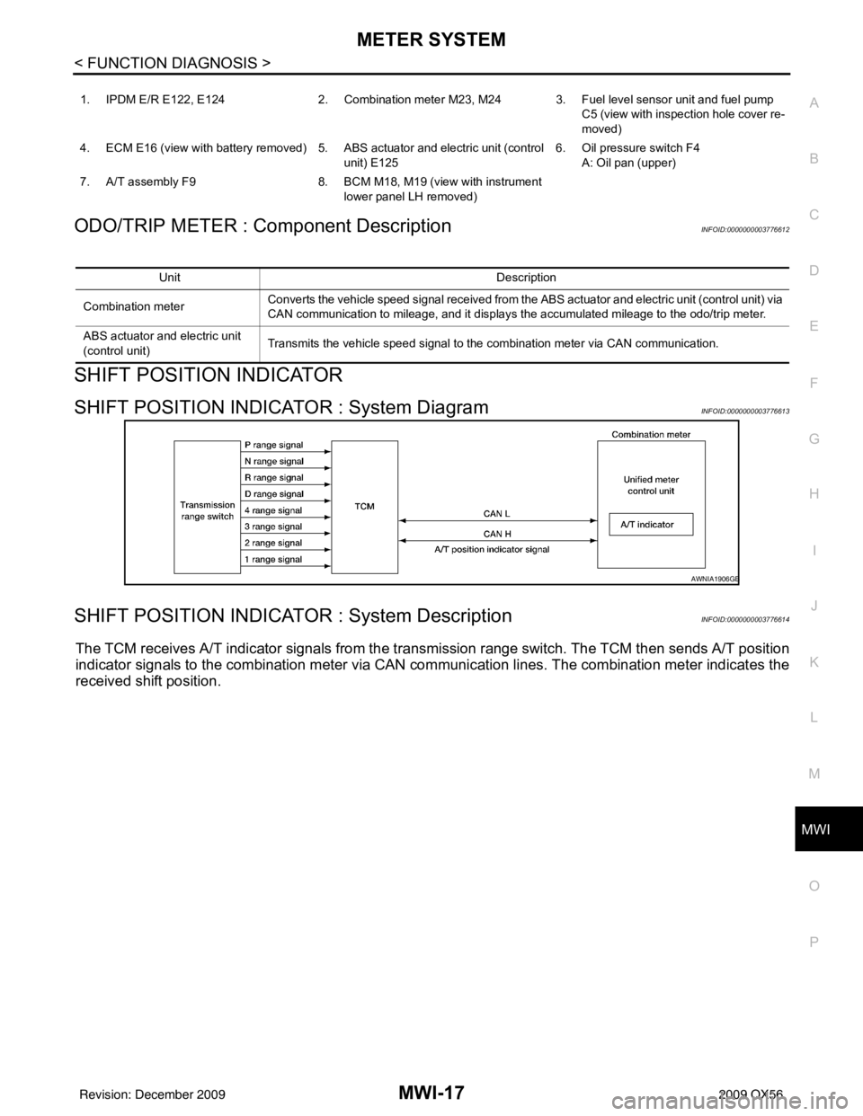
SHIFT POSITION INDICATOR
SHIFT POSITION INDICATOR : System DiagramINFOID:0000000003776613
SHIFT POSITION INDICATOR : System DescriptionINFOID:0000000003776614
The TCM receives A/T indicator signals from the tr ansmission range switch. The TCM then sends A/T position
indicator signals to the combination meter via CAN co mmunication lines. The combination meter indicates the
received shift position.
1. IPDM E/R E122, E124 2. Combination meter M23, M24 3. Fuel level sensor unit and fuel pump
C5 (view with inspection hole cover re-
moved)
4. ECM E16 (view with battery removed) 5. ABS actuator and electric unit (control unit) E1256. Oil pressure switch F4
A: Oil pan (upper)
7. A/T assembly F9 8. BCM M18, M19 (view with instrument
lower panel LH removed)
Unit Description
Combination meter Converts the vehicle speed signal
received from the ABS actuator and electric unit (control unit) via
CAN communication to mileage, and it displays the accumulated mileage to the odo/trip meter.
ABS actuator and electric unit
(control unit) Transmits the vehicle speed signal to the combination meter via CAN communication.
AWNIA1906GB
Revision: December 20092009 QX56
Page 2740 of 4171
MWI-18
< FUNCTION DIAGNOSIS >
METER SYSTEM
SHIFT POSITION INDICATOR : Component Parts Location
INFOID:0000000003776615
SHIFT POSITION INDICATOR : Component DescriptionINFOID:0000000003776616
WARNING LAMPS/INDICATOR LAMPS
WARNING LAMPS/INDICATOR LAMPS : System DiagramINFOID:0000000003776617
1. IPDM E/R E122, E124 2. Combination meter M23, M24 3. Fuel level sensor unit and fuel pump
C5 (view with inspection hole cover re-
moved)
4. ECM E16 (view with battery removed) 5. ABS actuator and electric unit (control
unit) E125 6. Oil pressure switch F4
A: Oil pan (upper)
7. A/T assembly F9 8. BCM M18, M19 (view with instrument
lower panel LH removed)
AWNIA0201ZZ
Unit Description
Combination meter Displays the shift position on the information display using shift position signal received from TCM.
TCM Transmits the shift position signal to the combination meter via CAN communication.
JSNIA0449GB
Revision: December 20092009 QX56