2009 INFINITI QX56 oil temperature
[x] Cancel search: oil temperaturePage 3608 of 4171
POWER STEERING OIL PUMPST-17
< ON-VEHICLE REPAIR >
C
DE
F
H I
J
K L
M A
B
ST
N
O P
POWER STEERING OIL PUMP
On-Vehicle Inspection and ServiceINFOID:0000000004187603
CHECKING RELIEF OIL PRESSURE
CAUTION:
Before starting work, confirm belt tension is proper.
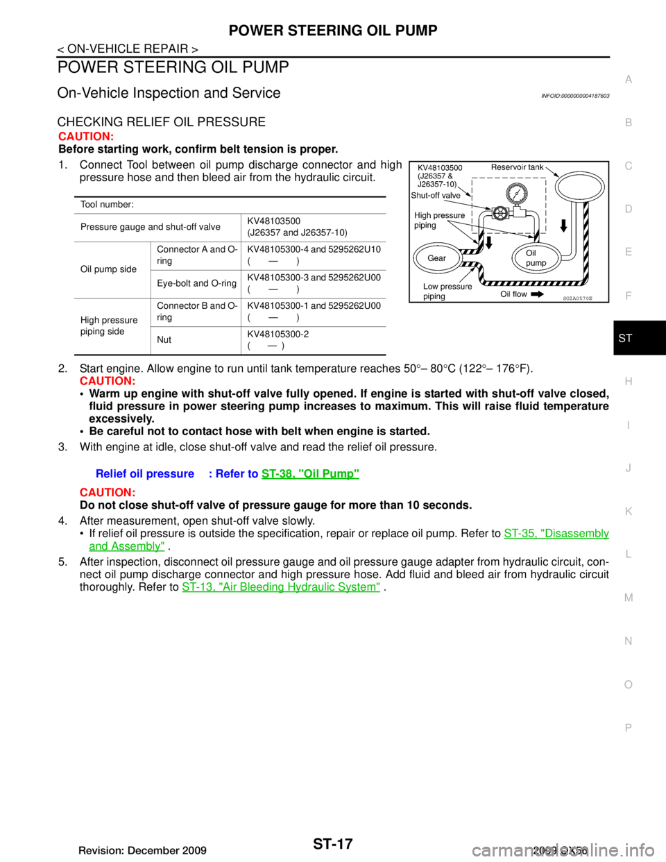
1. Connect Tool between oil pump discharge connector and high pressure hose and then bleed air from the hydraulic circuit.
2. Start engine. Allow engine to run until tank temperature reaches 50 °– 80 °C (122 °– 176 °F).
CAUTION:
Warm up engine with shut-off valve fully opened. If engine is started with shut-off valve closed,
fluid pressure in power steering pump increases to maximum. This will raise fluid temperature
excessively.
Be careful not to contact hose with belt when engine is started.
3. With engine at idle, close shut-off valve and read the relief oil pressure.
CAUTION:
Do not close shut-off valve of pressu re gauge for more than 10 seconds.
4. After measurement, open shut-off valve slowly. If relief oil pressure is outside the specific ation, repair or replace oil pump. Refer to ST-35, "Disassembly
and Assembly" .
5. After inspection, disconnect oil pressure gauge and oil pressure gauge adapter from hydraulic circuit, con-
nect oil pump discharge connector and high pressure hose. Add fluid and bleed air from hydraulic circuit
thoroughly. Refer to ST-13, "Air Bleeding Hydraulic System"
.
Tool number:
Pressure gauge and shut-off valve KV48103500
(J26357 and J26357-10)
Oil pump side Connector A and O-
ring
KV48105300-4 and 5295262U10
(—)
Eye-bolt and O-ring KV48105300-3 and 5295262U00
(—)
High pressure
piping side Connector B and O-
ring
KV48105300-1 and 5295262U00
(—)
Nut KV48105300-2
( — )
SGIA0570E
Relief oil pressure : Refer to
ST-38, "Oil Pump"
Revision: December 20092009 QX56
Page 3672 of 4171
TM-24
< FUNCTION DIAGNOSIS >
A/T CONTROL SYSTEM
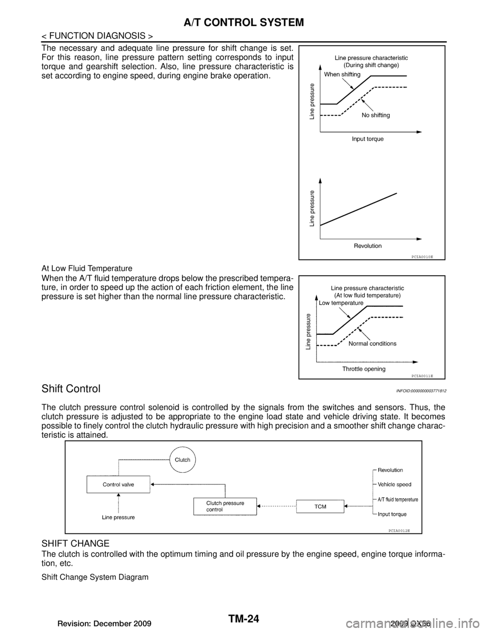
The necessary and adequate line pressure for shift change is set.
For this reason, line pressure pattern setting corresponds to input
torque and gearshift selection. Also, line pressure characteristic is
set according to engine speed, during engine brake operation.
At Low Fluid Temperature
When the A/T fluid temperature drops below the prescribed tempera-
ture, in order to speed up the action of each friction element, the line
pressure is set higher than the normal line pressure characteristic.
Shift ControlINFOID:0000000003771812
The clutch pressure control solenoid is controlled by the signals from the switches and sensors. Thus, the
clutch pressure is adjusted to be appropriate to the engine load state and vehicle driving state. It becomes
possible to finely control the clutch hydraulic pressu re with high precision and a smoother shift change charac-
teristic is attained.
SHIFT CHANGE
The clutch is controlled with the optimum timing and oil pressure by the engine speed, engine torque informa-
tion, etc.
Shift Change System Diagram
PCIA0010E
PCIA0011E
PCIA0012E
Revision: December 20092009 QX56
Page 3771 of 4171
SYSTEM SYMPTOMTM-123
< SYMPTOM DIAGNOSIS >
CEF
G H
I
J
K L
M A
B
TM
N
O P
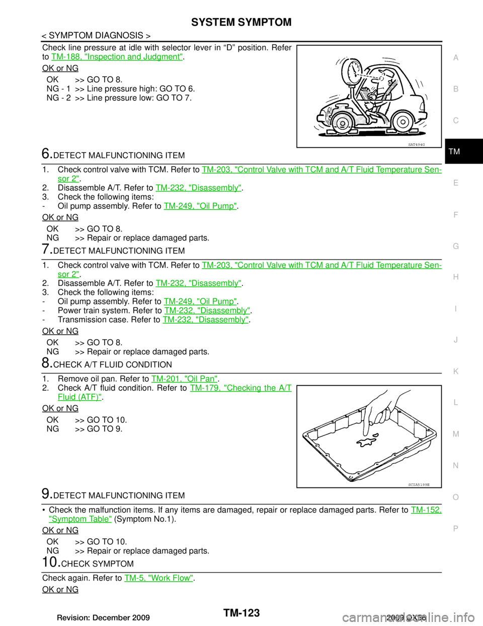
Check line pressure at idle with selector lever in “D” position. Refer
to TM-188, "Inspection and Judgment"
.
OK or NG
OK >> GO TO 8.
NG - 1 >> Line pressure high: GO TO 6.
NG - 2 >> Line pressure low: GO TO 7.
6.DETECT MALFUNCTIONING ITEM
1. Check control valve with TCM. Refer to TM-203, "Control Valve with TCM and A/T Fluid Temperature Sen-
sor 2".
2. Disassemble A/T. Refer to TM-232, "Disassembly"
.
3. Check the following items:
- Oil pump assembly. Refer to TM-249, "Oil Pump"
.
OK or NG
OK >> GO TO 8.
NG >> Repair or replace damaged parts.
7.DETECT MALFUNCTIONING ITEM
1. Check control valve with TCM. Refer to TM-203, "Control Valve with TCM and A/T Fluid Temperature Sen-
sor 2".
2. Disassemble A/T. Refer to TM-232, "Disassembly"
.
3. Check the following items:
- Oil pump assembly. Refer to TM-249, "Oil Pump"
.
- Power train system. Refer to TM-232, "Disassembly"
.
- Transmission case. Refer to TM-232, "Disassembly"
.
OK or NG
OK >> GO TO 8.
NG >> Repair or replace damaged parts.
8.CHECK A/T FLUID CONDITION
1. Remove oil pan. Refer to TM-201, "Oil Pan"
.
2. Check A/T fluid condition. Refer to TM-179, "Checking the A/T
Fluid (ATF)".
OK or NG
OK >> GO TO 10.
NG >> GO TO 9.
9.DETECT MALFUNCTIONING ITEM
Check the malfunction items. If any items are damaged, repair or replace damaged parts. Refer to TM-152,
"Symptom Table" (Symptom No.1).
OK or NG
OK >> GO TO 10.
NG >> Repair or replace damaged parts.
10.CHECK SYMPTOM
Check again. Refer to TM-5, "Work Flow"
.
OK or NG
SAT494G
SCIA5199E
Revision: December 20092009 QX56
Page 3773 of 4171

SYSTEM SYMPTOMTM-125
< SYMPTOM DIAGNOSIS >
CEF
G H
I
J
K L
M A
B
TM
N
O P
Refer to TM-186, "Inspection and Judgment".
OK or NG
OK >> GO TO 6.
OK in “1” position, NG in “R” position>>GO TO 5.
NG in both “1” and “R” positions>>GO TO 8.
5.DETECT MALFUNCTIONING ITEM
1. Disassemble A/T. Refer to TM-232, "Disassembly"
.
2. Check the following items:
- Reverse brake. Refer to TM-232, "Disassembly"
.
OK or NG
OK >> GO TO 9.
NG >> Repair or replace damaged parts.
6.CHECK LINE PRESSURE
Check the line pressure with the engine idling. Refer to TM-188,
"Inspection and Judgment".
OK or NG
OK >> GO TO 9.
NG - 1 >> Line pressure high. GO TO 7.
NG - 2 >> Line pressure low. GO TO 8.
7.DETECT MALFUNCTIONING ITEM
1. Check control valve with TCM. Refer to TM-203, "Control Valve with TCM and A/T Fluid Temperature Sen-
sor 2".
2. Disassemble A/T. Refer to TM-232, "Disassembly"
.
3. Check the following items:
- Oil pump assembly. Refer to TM-249, "Oil Pump"
.
OK or NG
OK >> GO TO 9.
NG >> Repair or replace damaged parts.
8.DETECT MALFUNCTIONING ITEM
1. Check control valve with TCM. Refer to TM-203, "Control Valve with TCM and A/T Fluid Temperature Sen-
sor 2".
2. Disassemble A/T. Refer to TM-232, "Disassembly"
.
3. Check the following items:
- Oil pump assembly. Refer to TM-249, "Oil Pump"
.
- Power train system. Refer to TM-232, "Disassembly"
.
- Transmission case. Refer to TM-232, "Disassembly"
.
OK or NG
OK >> GO TO 9.
NG >> Repair or replace damaged parts.
9.CHECK A/T FLUID CONDITION
1. Remove oil pan. Refer to TM-201, "Oil Pan"
.
SAT493G
SAT494G
Revision: December 20092009 QX56
Page 3775 of 4171
SYSTEM SYMPTOMTM-127
< SYMPTOM DIAGNOSIS >
CEF
G H
I
J
K L
M A
B
TM
N
O P
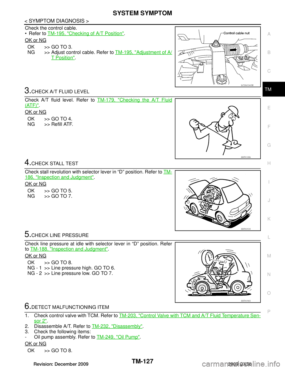
Check the control cable.
Refer to TM-195, "Checking of A/T Position"
.
OK or NG
OK >> GO TO 3.
NG >> Adjust control cable. Refer to TM-195, "Adjustment of A/
T Position".
3.CHECK A/T FLUID LEVEL
Check A/T fluid level. Refer to TM-179, "Checking the A/T Fluid
(ATF)".
OK or NG
OK >> GO TO 4.
NG >> Refill ATF.
4.CHECK STALL TEST
Check stall revolution with selector lever in “D” position. Refer to TM-
186, "Inspection and Judgment".
OK or NG
OK >> GO TO 5.
NG >> GO TO 7.
5.CHECK LINE PRESSURE
Check line pressure at idle with selector lever in “D” position. Refer
to TM-188, "Inspection and Judgment"
.
OK or NG
OK >> GO TO 8.
NG - 1 >> Line pressure high. GO TO 6.
NG - 2 >> Line pressure low. GO TO 7.
6.DETECT MALFUNCTIONING ITEM
1. Check control valve with TCM. Refer to TM-203, "Control Valve with TCM and A/T Fluid Temperature Sen-
sor 2".
2. Disassemble A/T. Refer to TM-232, "Disassembly"
.
3. Check the following items:
- Oil pump assembly. Refer to TM-249, "Oil Pump"
.
OK or NG
OK >> GO TO 8.
LCIA0345E
SAT638A
SAT493G
SAT494G
Revision: December 20092009 QX56
Page 3776 of 4171
TM-128
< SYMPTOM DIAGNOSIS >
SYSTEM SYMPTOM
NG >> Repair or replace damaged parts.
7.DETECT MALFUNCTIONING ITEM
1. Check control valve with TCM. Refer to TM-203, "Control Valve with TCM and A/T Fluid Temperature Sen-
sor 2".
2. Disassemble A/T. Refer to TM-232, "Disassembly"
.
3. Check the following items:
- Oil pump assembly. Refer to TM-249, "Oil Pump"
.
- Power train system. Refer to TM-232, "Disassembly"
.
- Transmission case. Refer to TM-232, "Disassembly"
.
OK or NG
OK >> GO TO 8.
NG >> Repair or replace damaged parts.
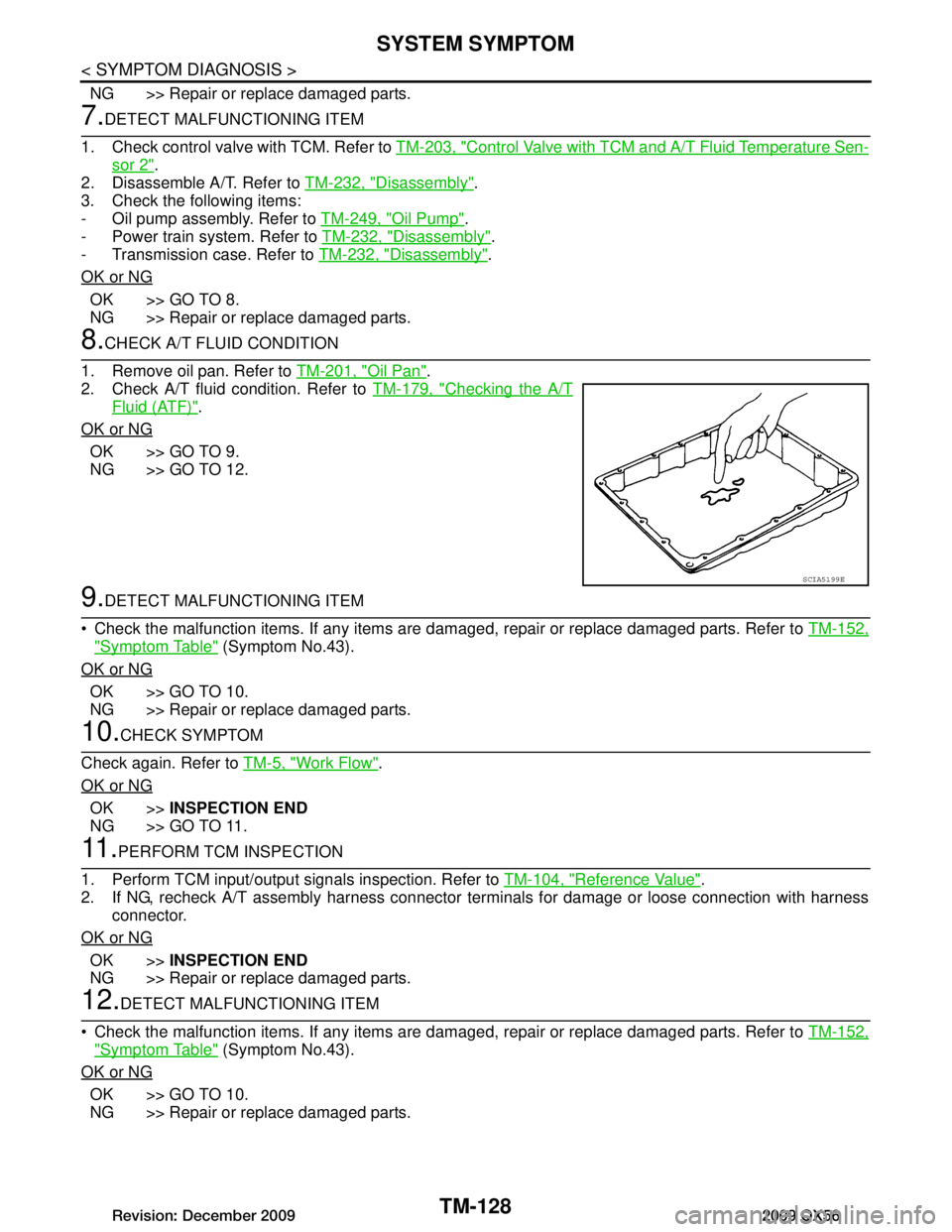
8.CHECK A/T FLUID CONDITION
1. Remove oil pan. Refer to TM-201, "Oil Pan"
.
2. Check A/T fluid condition. Refer to TM-179, "Checking the A/T
Fluid (ATF)".
OK or NG
OK >> GO TO 9.
NG >> GO TO 12.
9.DETECT MALFUNCTIONING ITEM
Check the malfunction items. If any items are dam aged, repair or replace damaged parts. Refer to TM-152,
"Symptom Table" (Symptom No.43).
OK or NG
OK >> GO TO 10.
NG >> Repair or replace damaged parts.
10.CHECK SYMPTOM
Check again. Refer to TM-5, "Work Flow"
.
OK or NG
OK >> INSPECTION END
NG >> GO TO 11.
11 .PERFORM TCM INSPECTION
1. Perform TCM input/output signals inspection. Refer to TM-104, "Reference Value"
.
2. If NG, recheck A/T assembly harness connector terminals for damage or loose connection with harness
connector.
OK or NG
OK >> INSPECTION END
NG >> Repair or replace damaged parts.
12.DETECT MALFUNCTIONING ITEM
Check the malfunction items. If any items are dam aged, repair or replace damaged parts. Refer to TM-152,
"Symptom Table" (Symptom No.43).
OK or NG
OK >> GO TO 10.
NG >> Repair or replace damaged parts.
SCIA5199E
Revision: December 20092009 QX56
Page 3777 of 4171
SYSTEM SYMPTOMTM-129
< SYMPTOM DIAGNOSIS >
CEF
G H
I
J
K L
M A
B
TM
N
O P
Vehicle Cannot Be Started from D1INFOID:0000000003771998
SYMPTOM:
Vehicle cannot be started from D1 on cruise test - Part 1.
DIAGNOSTIC PROCEDURE
1.CONFIRM THE SYMPTOM
Check if vehicle creeps in “R” position.
OK or NG
OK >> GO TO 2.
NG >> Refer to TM-124, "Vehicle Does Not Creep Backward in "R" Position"
.
2.CHECK SELF-DIAGNOSTIC RESULTS
Perform self-diagnosis. Refer to TM-32, "CONSULT-III Function (TRANSMISSION)"
.
Is any malfunction detected by self-diagnostic results?
YES >> Check the malfunctioning system.
NO >> GO TO 3.
3.CHECK ACCELERATOR PEDA L POSITION(APP) SENSOR
Check accelerator pedal position (APP) sensor. Refer to TM-70, "Diagnosis Procedure"
.
OK or NG
OK >> GO TO 4.
NG >> Repair or replace accelerator pedal position (APP) sensor.
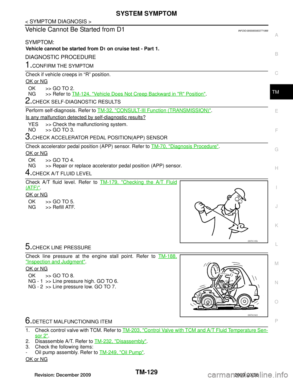
4.CHECK A/T FLUID LEVEL
Check A/T fluid level. Refer to TM-179, "Checking the A/T Fluid
(ATF)".
OK or NG
OK >> GO TO 5.
NG >> Refill ATF.
5.CHECK LINE PRESSURE
Check line pressure at the engine stall point. Refer to TM-188,
"Inspection and Judgment".
OK or NG
OK >> GO TO 8.
NG - 1 >> Line pressure high. GO TO 6.
NG - 2 >> Line pressure low. GO TO 7.
6.DETECT MALFUNCTIONING ITEM
1. Check control valve with TCM. Refer to TM-203, "Control Valve with TCM and A/T Fluid Temperature Sen-
sor 2".
2. Disassemble A/T. Refer to TM-232, "Disassembly"
.
3. Check the following items:
- Oil pump assembly. Refer to TM-249, "Oil Pump"
.
OK or NG
SAT638A
SAT494G
Revision: December 20092009 QX56
Page 3778 of 4171
TM-130
< SYMPTOM DIAGNOSIS >
SYSTEM SYMPTOM
OK >> GO TO 8.
NG >> Repair or replace damaged parts.
7.DETECT MALFUNCTIONING ITEM
1. Check control valve with TCM. Refer to TM-203, "Control Valve with TCM and A/T Fluid Temperature Sen-
sor 2".
2. Disassemble A/T. Refer to TM-232, "Disassembly"
.
3. Check the following items:
- Oil pump assembly. Refer to TM-249, "Oil Pump"
.
- Power train system. Refer to TM-232, "Disassembly"
.
- Transmission case. Refer to TM-232, "Disassembly"
.
OK or NG
OK >> GO TO 8.
NG >> Repair or replace damaged parts.
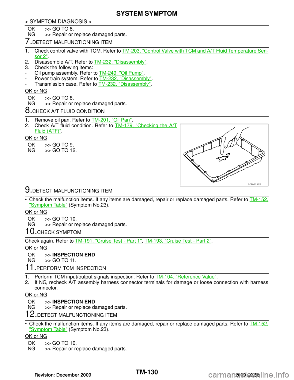
8.CHECK A/T FLUID CONDITION
1. Remove oil pan. Refer to TM-201, "Oil Pan"
.
2. Check A/T fluid condition. Refer to TM-179, "Checking the A/T
Fluid (ATF)".
OK or NG
OK >> GO TO 9.
NG >> GO TO 12.
9.DETECT MALFUNCTIONING ITEM
Check the malfunction items. If any items are dam aged, repair or replace damaged parts. Refer to TM-152,
"Symptom Table" (Symptom No.23).
OK or NG
OK >> GO TO 10.
NG >> Repair or replace damaged parts.
10.CHECK SYMPTOM
Check again. Refer to TM-191, "Cruise Test - Part 1"
, TM-193, "Cruise Test - Part 2".
OK or NG
OK >> INSPECTION END
NG >> GO TO 11.
11 .PERFORM TCM INSPECTION
1. Perform TCM input/output signals inspection. Refer to TM-104, "Reference Value"
.
2. If NG, recheck A/T assembly harness connector terminals for damage or loose connection with harness
connector.
OK or NG
OK >> INSPECTION END
NG >> Repair or replace damaged parts.
12.DETECT MALFUNCTIONING ITEM
Check the malfunction items. If any items are dam aged, repair or replace damaged parts. Refer to TM-152,
"Symptom Table" (Symptom No.23).
OK or NG
OK >> GO TO 10.
NG >> Repair or replace damaged parts.
SCIA5199E
Revision: December 20092009 QX56