Page 1836 of 4171

DRIVE BELTSEM-13
< ON-VEHICLE MAINTENANCE >
C
DE
F
G H
I
J
K L
M A
EM
NP
O
ON-VEHICLE MAINTENANCE
DRIVE BELTS
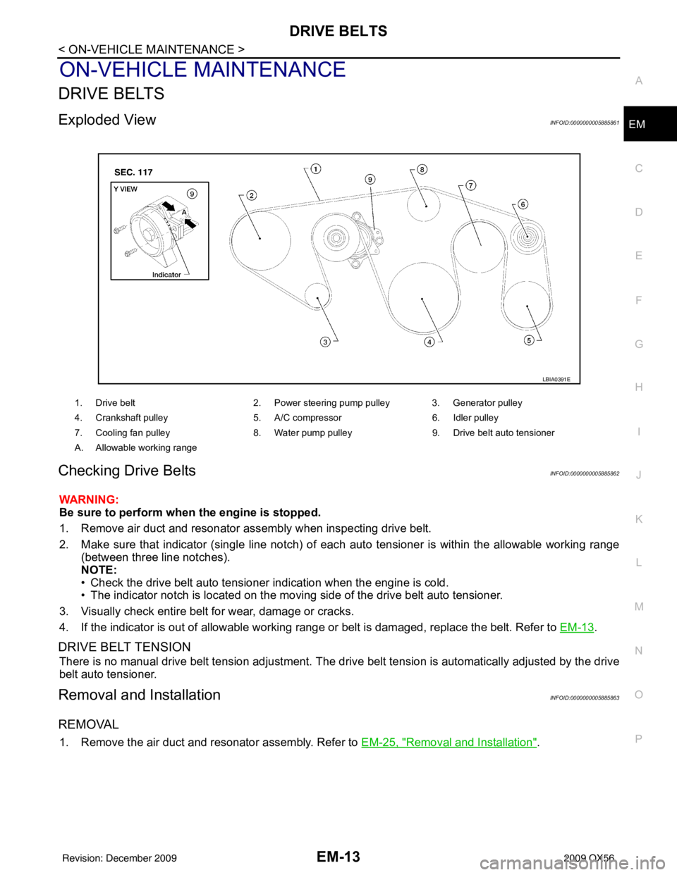
Exploded ViewINFOID:0000000005885861
Checking Drive BeltsINFOID:0000000005885862
WARNING:
Be sure to perform when the engine is stopped.
1. Remove air duct and resonator assembly when inspecting drive belt.
2. Make sure that indicator (single line notch) of eac
h auto tensioner is within the allowable working range
(between three line notches).
NOTE:
• Check the drive belt auto tensioner indication when the engine is cold.
• The indicator notch is located on the moving side of the drive belt auto tensioner.
3. Visually check entire belt for wear, damage or cracks.
4. If the indicator is out of allowable working range or belt is damaged, replace the belt. Refer to EM-13
.
DRIVE BELT TENSION
There is no manual drive belt tension adjustment. The driv e belt tension is automatically adjusted by the drive
belt auto tensioner.
Removal and InstallationINFOID:0000000005885863
REMOVAL
1. Remove the air duct and resonator assembly. Refer to EM-25, "Removal and Installation".
1. Drive belt2. Power steering pump pulley 3. Generator pulley
4. Crankshaft pulley 5. A/C compressor6. Idler pulley
7. Cooling fan pulley 8. Water pump pulley9. Drive belt auto tensioner
A. Allowable working range
LBIA0391E
Revision: December 20092009 QX56
Page 1837 of 4171

EM-14
< ON-VEHICLE MAINTENANCE >
DRIVE BELTS
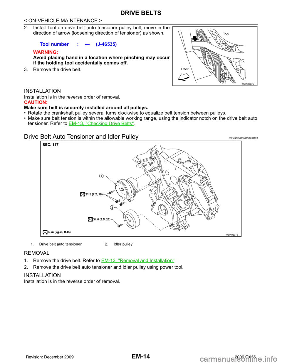
2. Install Tool on drive belt auto tensioner pulley bolt, move in thedirection of arrow (loosening direction of tensioner) as shown.
WARNING:
Avoid placing hand in a locatio n where pinching may occur
if the holding tool accidentally comes off.
3. Remove the drive belt.
INSTALLATION
Installation is in the reverse order of removal.
CAUTION:
Make sure belt is securely installed around all pulleys.
• Rotate the crankshaft pulley several turns clockwise to equalize belt tension between pulleys.
• Make sure belt tension is within the allowable working range, using the indicator notch on the drive belt auto tensioner. Refer to EM-13, "
Checking Drive Belts".
Drive Belt Auto Tensioner and Idler PulleyINFOID:0000000005885864
REMOVAL
1. Remove the drive belt. Refer to EM-13, "Removal and Installation".
2. Remove the drive belt auto tensioner and idler pulley using power tool.
INSTALLATION
Installation is in the reverse order of removal. Tool number : — (J-46535)
WBIA0537E
WBIA0607E
1. Drive belt auto tensioner
2. Idler pulley
Revision: December 20092009 QX56
Page 1838 of 4171
AIR CLEANER FILTEREM-15
< ON-VEHICLE MAINTENANCE >
C
DE
F
G H
I
J
K L
M A
EM
NP
O
AIR CLEANER FILTER
Exploded ViewINFOID:0000000005885865
Removal and Installation (Viscous paper type)INFOID:0000000005885866
REMOVAL
NOTE:
• The viscous paper type filter does not
need cleaning between replacement intervals.
• Replace the air filter as necessary for periodic maintenance. Refer to MA-8, "
Introduction of Periodic Mainte-
nance".
1. Remove the air cleaner case (upper).
2. Remove the air cleaner filter from the air cleaner case (lower).
INSTALLATION
1. Install the new air cleaner filter in the air cleaner case (lower).
2. Install the air cleaner case (upper).
1. Air cleaner case (lower) 2. Air cleaner filter3. Air cleaner case (upper)
4. Air duct and resonator assembly Front
ALBIA0413GB
Revision: December 20092009 QX56
Page 1839 of 4171
EM-16
< ON-VEHICLE MAINTENANCE >
SPARK PLUG
SPARK PLUG
Exploded ViewINFOID:0000000005885867
Removal and InstallationINFOID:0000000005885868
REMOVAL
1. Disconnect the harness connector from the ignition coil.
2. Remove ignition coil. CAUTION:
Do not shock ig nition coil.
3. Remove spark plug using suitable tool.
INSPECTION AFTER REMOVAL
• Do not use a wire brush for cleaning.
• If plug tip is covered with carbon, spark plug cleaner may be used.
1. Ignition coil 2. Spark plug
WBIA0796E
SEM294A
Cleaner air pressure:
Less than 588 kPa (5.9 bar, 6 kg/cm
2, 85 psi)
Cleaning time: Less than 20 seconds
SMA773C
Revision: December 20092009 QX56
Page 1840 of 4171
SPARK PLUGEM-17
< ON-VEHICLE MAINTENANCE >
C
DE
F
G H
I
J
K L
M A
EM
NP
O
• Checking and adjusting plug gap is not required between change
intervals.
INSTALLATION
Installation is in the reverse order of removal.
Spark Plug Types
*: Always check with the Parts Department for the latest parts information
CAUTION:
Do not drop or shock spark plug.
SMA806CA
Make NGK
Model Standard model
Standard type* DILFR5A-11
Gap (Nominal) 1.1 mm (0.043 in)
Revision: December 20092009 QX56
Page 1841 of 4171

EM-18
< ON-VEHICLE MAINTENANCE >
CAMSHAFT VALVE CLEARANCE
CAMSHAFT VALVE CLEARANCE
Valve ClearanceINFOID:0000000005885869
INSPECTION
NOTE:
Perform the following inspection after removal, installation or replacement of camshaft or valve-related parts,
or if there are unusual engine conditions due to changes in valve clearance over time (starting, idling, and/or
noise).
1. Warm up the engine. Then stop the engine.
2. Remove the air duct and resonator assembly. Refer to EM-25, "
Removal and Installation".
3. Remove the RH bank and LH bank rocker covers using power tool. Refer to EM-38, "
Removal and Instal-
lation".
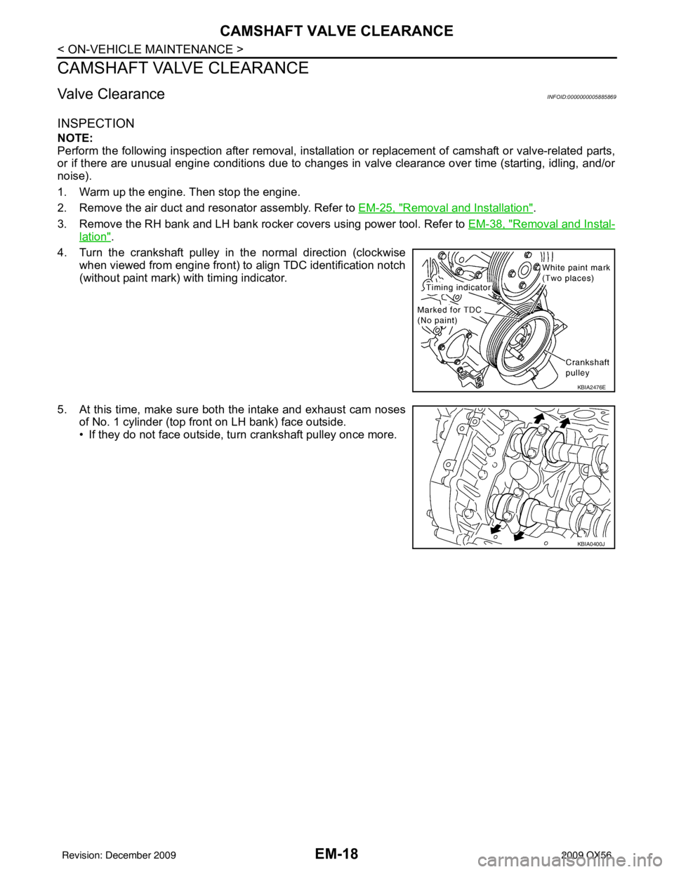
4. Turn the crankshaft pulley in the normal direction (clockwise when viewed from engine front) to align TDC identification notch
(without paint mark) with timing indicator.
5. At this time, make sure both the intake and exhaust cam noses of No. 1 cylinder (top front on LH bank) face outside.
• If they do not face outside, turn crankshaft pulley once more.
KBIA2476E
KBIA0400J
Revision: December 20092009 QX56
Page 1842 of 4171

CAMSHAFT VALVE CLEARANCEEM-19
< ON-VEHICLE MAINTENANCE >
C
DE
F
G H
I
J
K L
M A
EM
NP
O
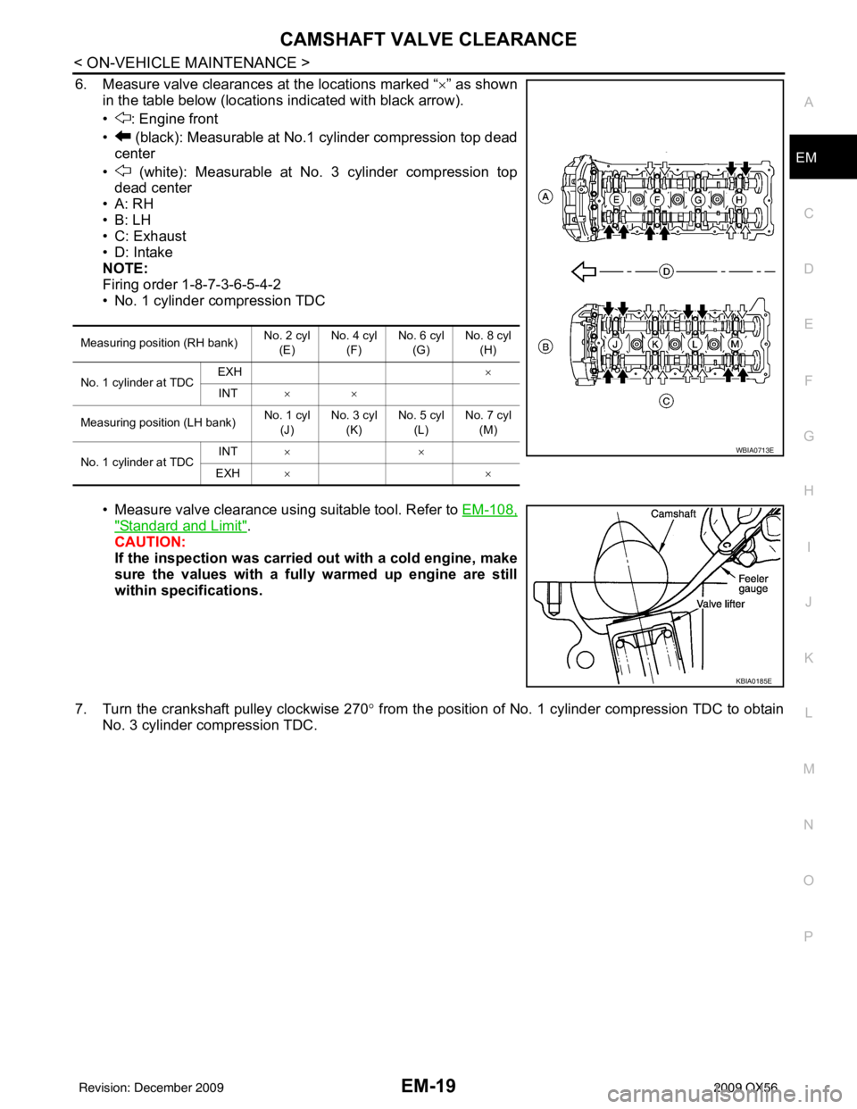
6. Measure valve clearances at the locations marked “×
” as shown
in the table below (locations indicated with black arrow).
• : Engine front
• (black): Measurable at No.1 cylinder compression top dead center
• (white): Measurable at No. 3 cylinder compression top dead center
•A: RH
•B: LH
• C: Exhaust
• D: Intake
NOTE:
Firing order 1-8-7-3-6-5-4-2
• No. 1 cylinder compression TDC
• Measure valve clearance using suitable tool. Refer to EM-108,
"Standard and Limit".
CAUTION:
If the inspection was carried out with a cold engine, make
sure the values with a fully warmed up engine are still
within specifications.
7. Turn the crankshaft pulley clockwise 270 ° from the position of No. 1 cylinder compression TDC to obtain
No. 3 cylinder compression TDC.
Measuring position (RH bank) No. 2 cyl
(E) No. 4 cyl
(F) No. 6 cyl
(G) No. 8 cyl
(H)
No. 1 cylinder at TDC EXH
×
INT ××
Measuring position (LH bank) No. 1 cyl
(J) No. 3 cyl
(K) No. 5 cyl
(L) No. 7 cyl
(M)
No. 1 cylinder at TDC INT
××
EXH ××
WBIA0713E
KBIA0185E
Revision: December 20092009 QX56
Page 1843 of 4171
EM-20
< ON-VEHICLE MAINTENANCE >
CAMSHAFT VALVE CLEARANCE
8. Measure valve clearances at the locations marked “×” as shown
in the table below (locations indicated with white arrow).
• : Engine front
• (black): Measurable at No.1 cylinder compression top dead center
• (white): Measurable at No. 3 cylinder compression top dead center
•A: RH
•B: LH
• C: Exhaust
•D: Intake
NOTE:
Firing order 1-8-7-3-6-5-4-2
• No. 3 cylinder compression TDC
• Measure valve clearance using suitable tool. Refer to EM-108,
"Standard and Limit".
CAUTION:
If the inspection was carried out with a cold engine, make
sure the values with a fully warmed up engine are still
within specifications.
Measuring position (RH bank) No. 2 cyl
(E) No. 4 cyl
(F) No. 6 cyl
(G) No. 8 cyl
(H)
No. 3 cylinder at TDC EXH
×
INT ×
Measuring position (LH bank) No. 1 cyl
(J) No. 3 cyl
(K) No. 5 cyl
(L) No. 7 cyl
(M)
No. 3 cylinder at TDC INT
××
EXH ××
WBIA0713E
KBIA0185E
Revision: December 20092009 QX56