2009 INFINITI QX56 differential
[x] Cancel search: differentialPage 1322 of 4171
![INFINITI QX56 2009 Factory Service Manual
DLN-266
< DISASSEMBLY AND ASSEMBLY >[REAR FINAL DRIVE: R230]
REAR FINAL DRIVE
10. Apply anti-corrosive oil to the threads of the drive pinion and the
seating surface of the new drive pinion lock nut. INFINITI QX56 2009 Factory Service Manual
DLN-266
< DISASSEMBLY AND ASSEMBLY >[REAR FINAL DRIVE: R230]
REAR FINAL DRIVE
10. Apply anti-corrosive oil to the threads of the drive pinion and the
seating surface of the new drive pinion lock nut.](/manual-img/42/57031/w960_57031-1321.png)
DLN-266
< DISASSEMBLY AND ASSEMBLY >[REAR FINAL DRIVE: R230]
REAR FINAL DRIVE
10. Apply anti-corrosive oil to the threads of the drive pinion and the
seating surface of the new drive pinion lock nut. Then adjust the
drive pinion lock nut tightening torque using suitable tool (A),
and check the drive pinion bearing preload torque using Tool
(B).
CAUTION:
Do not reuse drive pinion lock nut.
Apply anti-corrosive oil to th e threads of the drive pinion
and the seating surface of the new drive pinion lock nut.
Adjust the drive pinion lock nut tightening torque to the lower limit first. Do not exceed the drive pinion lock nut
specified torque.
If the drive pinion bearing preload torque exceeds the specified value, replace collap sible spacer and tighten it
again to adjust. Do not lo osen drive pinion lock nut to
adjust the drive pinion bearing preload torque.
After adjustment, rotate dri ve pinion back and forth 2 to 3
times to check for unusual no ise, rotation malfunction,
and other malfunctions.
11. Check companion flange runout.
12. Install the differential case assembly.
Differential Assembly
1. Install side gear thrust washers with the same thickness as the ones installed prior to disassembly, or reinstall the old ones on
the side gears.
2. Install the side gears and side gear thrust washers into the dif- ferential case.
CAUTION:
Make sure that the circular clip is installed to side gears.
3. Install the pinion mate thrust washers to the two pinion mate gears. Then install the pinion mate gears with the pinion mate
thrust washers by aligning them in diagonally opposite positions
and rotating them into the differential case.Tool number B: ST3127S000 (J-25765-A)
Drive pinion bearing preload torque
: Refer to DLN-270, "Inspection and Adjustment"
WDIA0379E
SDIA0193J
SDIA2025E
Revision: December 20092009 QX56
Page 1323 of 4171
![INFINITI QX56 2009 Factory Service Manual
REAR FINAL DRIVEDLN-267
< DISASSEMBLY AND ASSEMBLY > [REAR FINAL DRIVE: R230]
C
EF
G H
I
J
K L
M A
B
DLN
N
O P
4. Align the lock pin hole on the differential case with the lock pin hole on the pinion INFINITI QX56 2009 Factory Service Manual
REAR FINAL DRIVEDLN-267
< DISASSEMBLY AND ASSEMBLY > [REAR FINAL DRIVE: R230]
C
EF
G H
I
J
K L
M A
B
DLN
N
O P
4. Align the lock pin hole on the differential case with the lock pin hole on the pinion](/manual-img/42/57031/w960_57031-1322.png)
REAR FINAL DRIVEDLN-267
< DISASSEMBLY AND ASSEMBLY > [REAR FINAL DRIVE: R230]
C
EF
G H
I
J
K L
M A
B
DLN
N
O P
4. Align the lock pin hole on the differential case with the lock pin hole on the pinion mate shaft, and install the pinion mate shaft.
5. Measure the side gear end play. If necessary, select the appro- priate side gear thrust washers. Refer to DLN-270, "Inspection
and Adjustment".
6. Drive a new lock pin into the pinion mate shaft until it is flush with the differential case using suitable tool.
CAUTION:
Do not reuse lock pin.
7. Align the matching mark of the differential case with the mark of the drive gear, then place the drive gear onto the differential
case.
8. Apply thread locking sealant into the threaded holes of the drive gear and install the bolts.
Use Genuine Medium Strength Thread Locking Sealant orequivalent. Refer to GI-15, "Recommended Chemical Prod-
ucts and Sealants".
CAUTION:
Make sure the drive gear b ack and threaded holes are
clean.
9. Tighten the drive gear bolts to the specified torque. After tighten- ing the drive gear bolts to the specified torque, tighten an addi-
tional 34 ° using Tool (A).
CAUTION:
Always use Tool. Avoid tighte ning based on visual check
alone.
Tighten drive gear bolts in a crisscross pattern.
SDIA0195J
WDIA0131E
SDIA2593E
SDIA2594E
Tool number : KV10112100-A (BT-8653-A)
AWBIA0722ZZ
Revision: December 20092009 QX56
Page 1324 of 4171
![INFINITI QX56 2009 Factory Service Manual
DLN-268
< DISASSEMBLY AND ASSEMBLY >[REAR FINAL DRIVE: R230]
REAR FINAL DRIVE
10. Press the side bearing inner races into the differential case
using Tools.
CAUTION:
Do not reuse side bearing inner r INFINITI QX56 2009 Factory Service Manual
DLN-268
< DISASSEMBLY AND ASSEMBLY >[REAR FINAL DRIVE: R230]
REAR FINAL DRIVE
10. Press the side bearing inner races into the differential case
using Tools.
CAUTION:
Do not reuse side bearing inner r](/manual-img/42/57031/w960_57031-1323.png)
DLN-268
< DISASSEMBLY AND ASSEMBLY >[REAR FINAL DRIVE: R230]
REAR FINAL DRIVE
10. Press the side bearing inner races into the differential case
using Tools.
CAUTION:
Do not reuse side bearing inner race.
11. Install the differential case assembly with the side bearing outer races into the gear carrier.
12. Measure the side bearing preload torque. If necessary, select the appropriate side bearing adjusting washers. Refer to DLN-
270, "Inspection and Adjustment".
13. Insert the selected left and right side bearing adjusting washers in place between the side bearings and gear carrier.
14. Install the side bearing caps with the matching marks aligned and tighten the side bearing cap bolts to the specified torque.
15. Check and adjust the drive gear runout, tooth contact, drive gear to drive pinion backlash, and total pre-
load torque.
Recheck the above items.
16. Install the side flanges. Tool number A: KV38100200 (J-26233)
B: ST33081000 ( — )
SPD353
SPD919
SPD924
SPD889
Revision: December 20092009 QX56
Page 1326 of 4171
![INFINITI QX56 2009 Factory Service Manual
DLN-270
< SERVICE DATA AND SPECIFICATIONS (SDS) [REAR FINAL DRIVE: R230]
SERVICE DATA AND SPECIFICATIONS (SDS)
SERVICE DATA AND SPECIFICATIONS (SDS)
SERVICE DATA AND SPECIFICATIONS (SDS)
General Spec INFINITI QX56 2009 Factory Service Manual
DLN-270
< SERVICE DATA AND SPECIFICATIONS (SDS) [REAR FINAL DRIVE: R230]
SERVICE DATA AND SPECIFICATIONS (SDS)
SERVICE DATA AND SPECIFICATIONS (SDS)
SERVICE DATA AND SPECIFICATIONS (SDS)
General Spec](/manual-img/42/57031/w960_57031-1325.png)
DLN-270
< SERVICE DATA AND SPECIFICATIONS (SDS) [REAR FINAL DRIVE: R230]
SERVICE DATA AND SPECIFICATIONS (SDS)
SERVICE DATA AND SPECIFICATIONS (SDS)
SERVICE DATA AND SPECIFICATIONS (SDS)
General SpecificationINFOID:0000000004193561
Inspection and AdjustmentINFOID:0000000004193562
DRIVE GEAR RUNOUT
Unit: mm (in)
SIDE GEAR CLEARANCE
Unit: mm (in)
PRELOAD TORQUE
Unit: N·m (kg-m, in-lb)
BACKLASH
Unit: mm (in)
COMPANION FLANGE RUNOUT
Unit: mm (in)
SELECTIVE PARTS
Side Gear Thrust Washer
Applied model VK56DE
A/T
Final drive model R230
Gear ratio 3.357
Number of teeth (Drive gear/Drive pinion) 47/14
Oil capacity (Approx.) 1.75 (3 3/4 US pt, 3 1/8 Imp pt)
Number of pinion gears 2
Drive pinion adjustment spacer type Collapsible
Item Runout limit
Drive gear back face 0.05 (0.0020) or less
Item Specification
Side gear back clearance
(Clearance limit between side gear and differential case for adjusting
side gear backlash) 0.20 (0.0079) or less
(Each gear should rotate smoothly without excessive resis- tance during differential motion.)
Item Specification
Drive pinion bearing preload torque 1.77 − 2.64 N·m (0.18 − 0.26 kg −m, 16 − 23 in-lb)
Side bearing preload torque (reference value determined by drive
gear bolt pulling force) 0.20
− 0.52 N·m (0.02 − 0.05 kg −m, 2 − 4 in-lb)
Drive gear bolt pulling force (by spring gauge) 34.2 − 39.2 N (3.5 − 4.0 kg, 7.7 − 8.8 lb)
Total preload torque
(Total preload torque = drive pinion bearing preload torque + Side
bearing preload torque) 2.05
− 4.11 N·m (0.21 − 0.42 kg −m, 19 − 36 in-lb)
Item Specification
Drive gear to drive pinion gear 0.13 − 0.18 (0.0051 − 0.0070)
Item Runout limit
Outer side of the companion flange 0.08 (0.0031) or less
Revision: December 20092009 QX56
Page 1931 of 4171

EM-108
< SERVICE DATA AND SPECIFICATIONS (SDS)
SERVICE DATA AND SPECIFICATIONS (SDS)
SERVICE DATA AND SPECIFICATIONS (SDS)
SERVICE DATA AND SPECIFICATIONS (SDS)
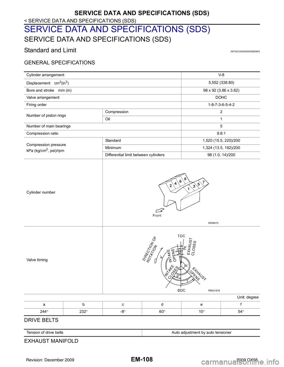
Standard and LimitINFOID:0000000005885905
GENERAL SPECIFICATIONS
DRIVE BELTS
EXHAUST MANIFOLD
Cylinder arrangementV- 8
Displacement cm
3(in3) 5,552 (338.80)
Bore and stroke mm (in) 98 x 92 (3.86 x 3.62)
Valve arrangement DOHC
Firing order 1-8-7-3-6-5-4-2
Number of piston rings Compression
2
Oil 1
Number of main bearings 5
Compression ratio 9.8:1
Compression pressure
kPa (kg/cm
2, psi)/rpm Standard 1,520 (15.5, 220)/200
Minimum
1,324 (13.5, 192)/200
Differential limit between cylinders 98 (1.0, 14)/200
Cylinder number
Valve timing Unit: degree
abcde f
244 ° 232° -8° 60° 10° 54°
SEM957C
PBIC0187E
Tension of drive belts Auto adjustment by auto tensioner
Revision: December 20092009 QX56
Page 2211 of 4171

TERMINOLOGYGI-17
< HOW TO USE THIS MANUAL >
C
DE
F
G H
I
J
K L
M B
GI
N
O P
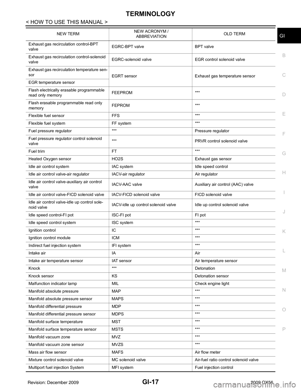
Exhaust gas recirculation control-BPT
valve EGRC-BPT valve
BPT valve
Exhaust gas recirculation control-solenoid
valve EGRC-solenoid valve
EGR control solenoid valve
Exhaust gas recirculation temperature sen-
sor EGRT sensorExhaust gas temperature sensor
EGR temperature sensor
Flash electrically erasable programmable
read only memory FEEPROM
***
Flash erasable programmable read only
memory FEPROM
***
Flexible fuel sensor FFS***
Flexible fuel system FF system***
Fuel pressure regulato r*** Pressure regulator
Fuel pressure regulator control solenoid
valve ***
PRVR control solenoid valve
Fuel trim FT***
Heated Oxygen sensor HO2S Exhaust gas sensor
Idle air control system IAC system Idle speed control
Idle air control valve-air regulato rIACV-air regulator Air regulator
Idle air control valve-auxiliary air control
valve IACV-AAC valve
Auxiliary air control (AAC) valve
Idle air control valve-FICD solenoid valve IACV-FICD solenoid valve FICD solenoid valve
Idle air control valve-idle up control sole-
noid valve IACV-idle up control solenoid valve Idle up control solenoid valve
Idle speed control-FI pot ISC-FI pot FI pot
Idle speed control system ISC system***
Ignition control IC***
Ignition control module ICM***
Indirect fuel injection system IFI system ***
Intake air IA Air
Intake air temperature sensor IAT sensor Air temperature sensor
Knock *** Detonation
Knock sensor KS Detonation sensor
Malfunction indicator lamp MIL Check engine light
Manifold absolute pressure MAP ***
Manifold absolute pressure sensor MAPS ***
Manifold differential pressure MDP ***
Manifold differential pressure sensor MDPS ***
Manifold su rface temperature MST ***
Manifold surface temperature sensor MSTS ***
Manifold vacuum zone MVZ ***
Manifold vacuum zone sensor MVZS***
Mass air flow sensor MAFS Air flow meter
Mixture control solenoid valve MC solenoid valveAir-fuel ratio control solenoid valve
Multiport fuel injection System MFI system Fuel injection control
NEW TERM
NEW ACRONYM /
ABBREVIATION OLD TERM
Revision: December 20092009 QX56
Page 2682 of 4171

PERIODIC MAINTENANCEMA-9
< ON-VEHICLE MAINTENANCE >
C
DE
F
G H
I
J
K L
M B
MA
N
O A
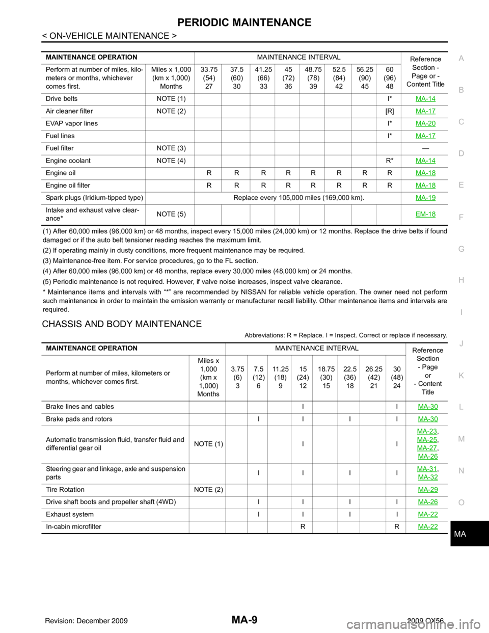
(1) After 60,000 miles (96,000 km) or 48 months, inspect every 15,000 miles (24,000 km) or 12 months. Replace the drive belts i
f found
damaged or if the auto belt tensioner reading reaches the maximum limit.
(2) If operating mainly in dusty conditions, more frequent maintenance may be required.
(3) Maintenance-free item. For service procedures, go to the FL section.
(4) After 60,000 miles (96,000 km) or 48 months, replace every 30,000 miles (48,000 km) or 24 months.
(5) Periodic maintenance is not required. However, if valve noise increases, inspect valve clearance.
* Maintenance items and inte rvals with “*” are recommended by NISSAN for reliable vehicle operation. The owner need not perform
such maintenance in order to maintain the emission warranty or manufacturer recall liability. Other maintenance items and inter vals are
required.
CHASSIS AND BODY MAINTENANCE
Abbreviations: R = Replace. I = Inspect. Correct or replace if necessary.
MAINTENANCE OPERATION MAINTENANCE INTERVAL
Reference
Section -
Page or -
Content Title
Perform at number of miles, kilo-
meters or months, whichever
comes first. Miles x 1,000
(km x 1,000) Months 33.75
(54)27 37.5
(60) 30 41.25
(66)33 45
(72) 36 48.75
(78)39 52.5
(84) 42 56.25
(90)45 60
(96) 48
Drive belts NOTE (1) I*MA-14
Air cleaner filter NOTE (2) [R]MA-17
EVAP vapor lines I*MA-20
Fuel lines I*MA-17
Fuel filter NOTE (3) —
Engine coolant NOTE (4) R*MA-14
Engine oil R R R R R R R R MA-18
Engine oil filterR R R R R R R R MA-18
Spark plugs (Iridium-tipped type)Replace every 105,000 miles (169,000 km).MA-19
Intake and exhaust valve clear-
ance*NOTE (5)
EM-18
MAINTENANCE OPERATIONMAINTENANCE INTERVAL
Reference
Section
- Page or
- Content
Title
Perform at number of miles, kilometers or
months, whichever comes first. Miles x
1,000(km x
1,000)
Months 3.75
(6)
3 7.5
(12)
6 11 . 2 5
(18)
9 15
(24)
12 18.75
(30)
15 22.5
(36)
18 26.25
(42)
21 30
(48)
24
Brake lines and cables IIMA-30
Brake pads and rotors II I IMA-30
Automatic transmission fluid, transfer fluid and
differential gear oil NOTE (1)
IIMA-23
,
MA-25
,
MA-27
,
MA-26
Steering gear and linkage, axle and suspension
parts II I I
MA-31,
MA-32
Tire Rotation NOTE (2) MA-29
Drive shaft boots and propeller shaft (4WD)II I IMA-26
Exhaust system II I IMA-22
In-cabin microfilter RRMA-22
Revision: December 20092009 QX56
Page 2683 of 4171

MA-10
< ON-VEHICLE MAINTENANCE >
PERIODIC MAINTENANCE
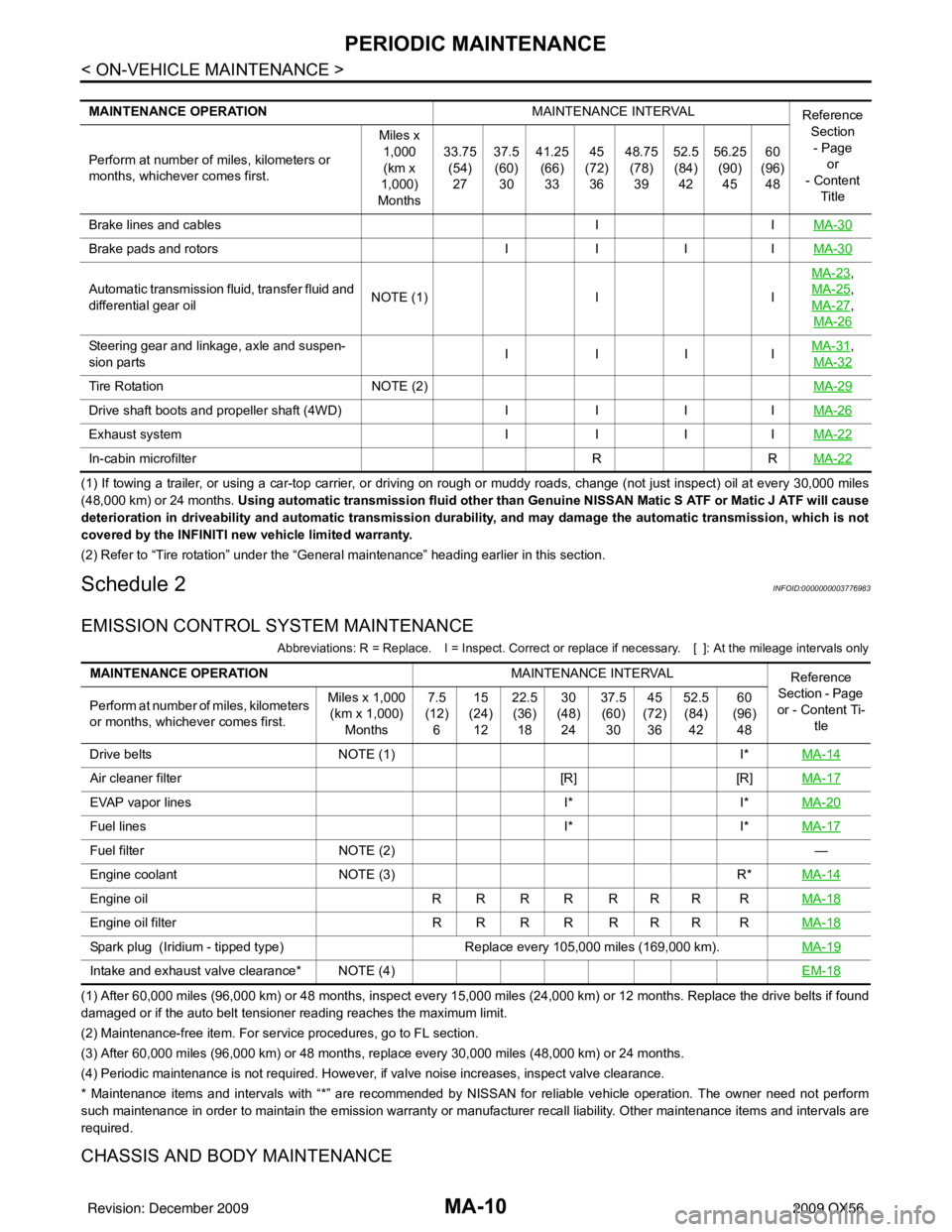
(1) If towing a trailer, or using a car-top carrier, or driving on rough or muddy roads, change (not just inspect) oil at every 30,000 miles
(48,000 km) or 24 months. Using automatic transmission fluid other than Genui ne NISSAN Matic S ATF or Matic J ATF will cause
deterioration in driveability and automatic transmission durability, and may damage the automatic transmission, which is not
covered by the INFINITI new vehicle limited warranty.
(2) Refer to “Tire rotation” unde r the “General maintenance” heading earlier in this section.
Schedule 2INFOID:0000000003776983
EMISSION CONTROL SYSTEM MAINTENANCE
Abbreviations: R = Replace. I = Inspect. Correct or r eplace if necessary. [ ]: At the mileage intervals only
(1) After 60,000 miles (96,000 km) or 48 months, inspect every 15,000 miles (24,000 km) or 12 months. Replace the drive belts if found
damaged or if the auto belt tensioner reading reaches the maximum limit.
(2) Maintenance-free item. For service procedures, go to FL section.
(3) After 60,000 miles (96,000 km) or 48 months, replace every 30,000 miles (48,000 km) or 24 months.
(4) Periodic maintenance is not required. However, if valve noise increases, inspect valve clearance.
* Maintenance items and intervals with “*” are recommended by NISSAN for reliable vehicle operation. The owner need not perform
such maintenance in order to maintain the emission warranty or manufacturer recall liability. Other maintenance items and inter vals are
required.
CHASSIS AND BODY MAINTENANCE
MAINTENANCE OPERATION MAINTENANCE INTERVAL
Reference
Section
- Page or
- Content
Title
Perform at number of miles, kilometers or
months, whichever comes first. Miles x
1,000(km x
1,000)
Months 33.75
(54)
27 37.5
(60)
30 41.25
(66)
33 45
(72)
36 48.75
(78)
39 52.5
(84)
42 56.25
(90)
45 60
(96)
48
Brake lines and cables IIMA-30
Brake pads and rotors IIIIMA-30
Automatic transmission fluid, transfer fluid and
differential gear oil NOTE (1)
IIMA-23
,
MA-25
,
MA-27
,
MA-26
Steering gear and linkage, axle and suspen-
sion parts IIIIMA-31,
MA-32
Tire Rotation NOTE (2) MA-29
Drive shaft boots and propeller shaft (4WD)IIIIMA-26
Exhaust system IIIIMA-22
In-cabin microfilter RRMA-22
MAINTENANCE OPERATION MAINTENANCE INTERVAL
Reference
Section - Page
or - Content Ti- tle
Perform at number of miles, kilometers
or months, whichever comes first. Miles x 1,000
(km x 1,000)
Months 7.5
(12)
6 15
(24)
12 22.5
(36)
18 30
(48)
24 37.5
(60)
30 45
(72)
36 52.5
(84)
42 60
(96)
48
Drive belts NOTE (1) I*MA-14
Air cleaner filter [R][R]MA-17
EVAP vapor lines I*I*MA-20
Fuel lines I*I*MA-17
Fuel filter NOTE (2) —
Engine coolant NOTE (3) R*MA-14
Engine oil R R R R R R R R MA-18
Engine oil filterR R R R R R R R MA-18
Spark plug (Iridium - tipped type) Replace every 105,000 miles (169,000 km).MA-19
Intake and exhaust valve clearance* NOTE (4) EM-18
Revision: December 20092009 QX56