Page 3490 of 4171

DIAGNOSIS SENSOR UNITSR-17
< ON-VEHICLE REPAIR >
C
DE
F
G
I
J
K L
M A
B
SR
N
O P
DIAGNOSIS SENSOR UNIT
Removal and InstallationINFOID:0000000003775164
REMOVAL
CAUTION:
• Before servicing the SRS, turn the ignition switch off, disconnect both battery cables and wait at least 3 minutes.
• Do not use old bolts; replace with new bolts.
• Check diagnosis sensor unit bracket to make sure it is free of deformities, dents, cracks or rust. If it
shows any visible signs of damage, replace with new one.
• Replace diagnosis sensor unit if it has been dropped or sustained an impact.
• When replacing the air bag diagno sis sensor unit, always check with the parts department for he lat-
est parts information. Installing an incorrect air bag diagnosis sensor unit may or may not cause the
air bag warning lamp to illuminate and may cause incorrect deployment of the supplemental air bags
and seat belt pre-tensioner in a collision r esulting in serious personal injury or death.
1. Always check the air bag diagnosis sensor unit E CU discriminated number (identification number) using
CONSULT-III.
2. Disconnect the negative and positive battery term inals, then wait at least three minutes.
3. Disconnect the harness connectors for each air bag module and seat belt pre-tensioner.
4. Remove center console. Refer to IP-20, "
Removal and Installation".
5. Disconnect diagnosis sensor unit harness connectors.
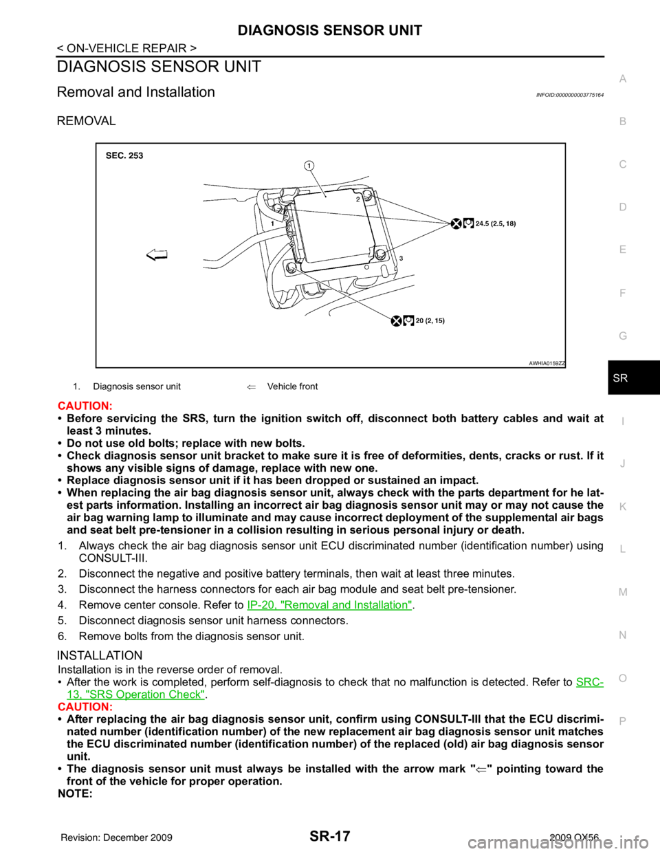
6. Remove bolts from the diagnosis sensor unit.
INSTALLATION
Installation is in the reverse order of removal.
• After the work is completed, perform self-diagnosis to check that no malfunction is detected. Refer to SRC-
13, "SRS Operation Check".
CAUTION:
• After replacing the air bag diagnosis sensor unit, confirm using CO NSULT-III that the ECU discrimi-
nated number (identification number) of the ne w replacement air bag diagnosis sensor unit matches
the ECU discriminated number (identification numb er) of the replaced (old) air bag diagnosis sensor
unit.
• The diagnosis sensor unit must always be installed with the arrow mark " ⇐" pointing toward the
front of the vehicle for proper operation.
NOTE:
1. Diagnosis sensor unit ⇐Vehicle front
AWHIA0159ZZ
Revision: December 20092009 QX56
Page 3964 of 4171

VTL-24
< ON-VEHICLE REPAIR >
MODE DOOR MOTOR
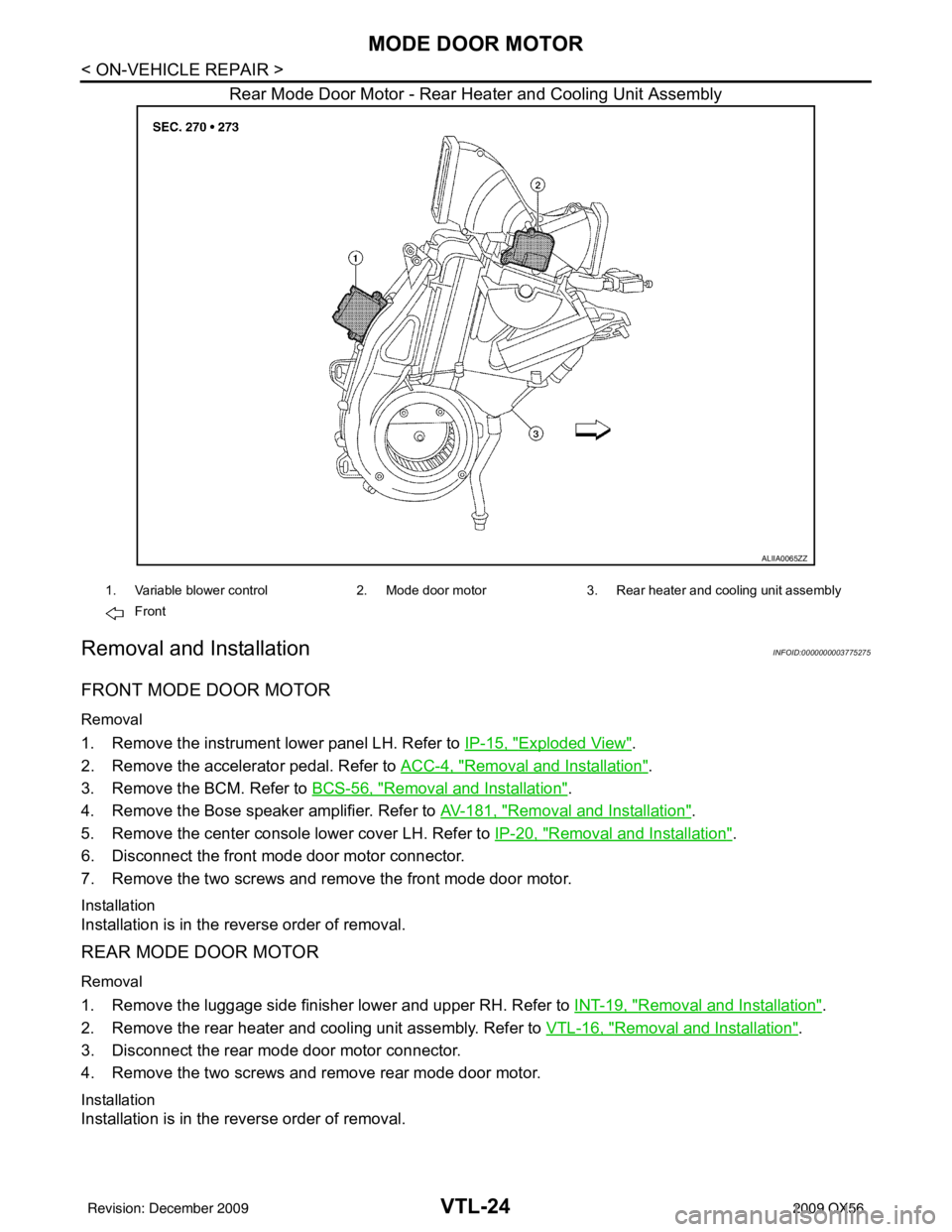
Rear Mode Door Motor - Rear Heater and Cooling Unit Assembly
Removal and InstallationINFOID:0000000003775275
FRONT MODE DOOR MOTOR
Removal
1. Remove the instrument lower panel LH. Refer to IP-15, "Exploded View".
2. Remove the accelerator pedal. Refer to ACC-4, "
Removal and Installation".
3. Remove the BCM. Refer to BCS-56, "
Removal and Installation".
4. Remove the Bose speaker amplifier. Refer to AV-181, "
Removal and Installation".
5. Remove the center console lower cover LH. Refer to IP-20, "
Removal and Installation".
6. Disconnect the front mode door motor connector.
7. Remove the two screws and remove the front mode door motor.
Installation
Installation is in the reverse order of removal.
REAR MODE DOOR MOTOR
Removal
1. Remove the luggage side finisher lower and upper RH. Refer to INT-19, "Removal and Installation".
2. Remove the rear heater and cooling unit assembly. Refer to VTL-16, "
Removal and Installation".
3. Disconnect the rear mode door motor connector.
4. Remove the two screws and remove rear mode door motor.
Installation
Installation is in the reverse order of removal.
ALIIA0065ZZ
1. Variable blower control 2. Mode door motor3. Rear heater and cooling unit assembly
Front
Revision: December 20092009 QX56
Page 3966 of 4171

VTL-26
< ON-VEHICLE REPAIR >
AIR MIX DOOR MOTOR
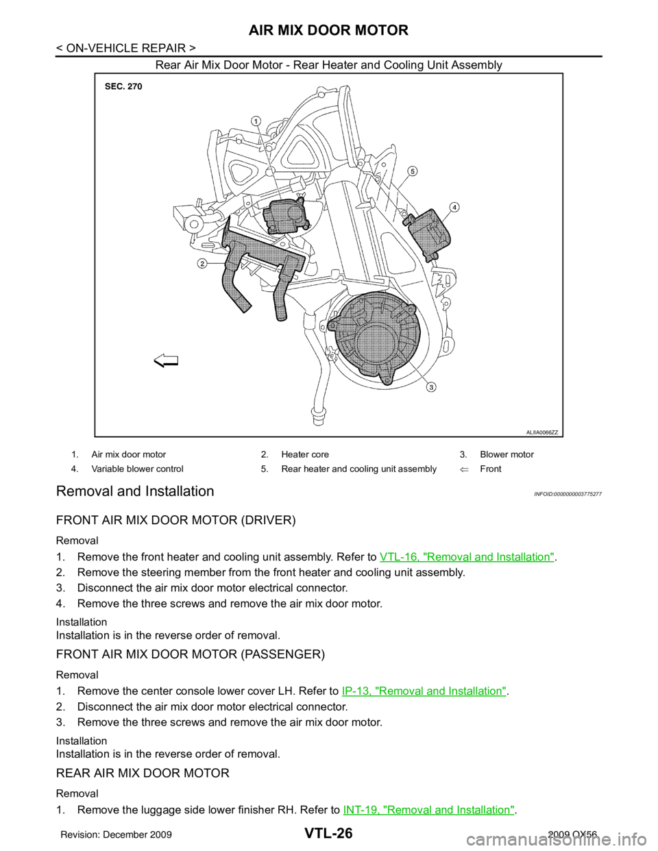
Rear Air Mix Door Motor - Rear Heater and Cooling Unit Assembly
Removal and InstallationINFOID:0000000003775277
FRONT AIR MIX DOOR MOTOR (DRIVER)
Removal
1. Remove the front heater and cooling unit assembly. Refer to VTL-16, "Removal and Installation".
2. Remove the steering member from the front heater and cooling unit assembly.
3. Disconnect the air mix door motor electrical connector.
4. Remove the three screws and remove the air mix door motor.
Installation
Installation is in the reverse order of removal.
FRONT AIR MIX DOOR MOTOR (PASSENGER)
Removal
1. Remove the center console lower cover LH. Refer to IP-13, "Removal and Installation".
2. Disconnect the air mix door motor electrical connector.
3. Remove the three screws and remove the air mix door motor.
Installation
Installation is in the reverse order of removal.
REAR AIR MIX DOOR MOTOR
Removal
1. Remove the luggage side lower finisher RH. Refer to INT-19, "Removal and Installation".
ALIIA0066ZZ
1. Air mix door motor2. Heater core 3. Blower motor
4. Variable blower control 5. Rear heater and cooling unit assembly ⇐Front
Revision: December 20092009 QX56
Page 3973 of 4171

DUCTS AND GRILLESVTL-33
< ON-VEHICLE REPAIR >
C
DE
F
G H
J
K L
M A
B
VTL
N
O P
Removal and InstallationINFOID:0000000003775281
CENTER CONSOLE HEAT DUCT AND RE AR FINISHER ASSEMBLY GRILLE
Removal
The center console must be removed and disassembled to remove the heat duct and rear finisher assembly
grille. Refer to IP-20, "
Removal and Installation".
Installation
Installation is in the reverse order of removal.
DEFROSTER NOZZLE
Removal
1. Remove the instrument panel trim. Refer to IP-13, "Removal and Installation".
2. Remove the front heater and cooling unit assembly. Refer to VTL-16, "
Removal and Installation".
3. Remove the defroster nozzle.
Installation
Installation is in the reverse order of removal.
RH AND LH SIDE DEMISTER DUCT
Removal
1. Remove the instrument panel trim. Refer to IP-13, "Removal and Installation".
2. Remove the RH or LH side demister duct screws.
3. Remove the RH or LH side demister duct.
Installation
Installation is in the reverse order of removal.
RH AND LH VENTILATOR DUCT
Removal
1. Remove the instrument panel trim. Refer to IP-13, "Removal and Installation".
2. Remove the front heater and cooling unit assembly. Refer to VTL-16, "
Removal and Installation".
3. Remove the RH or LH ventilator duct.
Installation
Installation is in the reverse order of removal.
CENTER VENTILATOR DUCT
Removal
1. Remove the instrument panel trim. Refer to IP-13, "Removal and Installation".
2. Remove the front heater and cooling unit assembly. Refer to VTL-16, "
Removal and Installation".
3. Remove the defroster nozzle.
4. Remove the RH and LH side demister ducts.
5. Remove the RH and LH ventilator ducts.
6. Remove the center ventilator duct.
Installation
Installation is in the reverse order of removal.
FLOOR DUCT
Removal
1. Remove the floor carpet. Refer to INT-16, "Removal and Installation".
2. Remove the two clips and remove the floor duct.
Installation
Installation is in the reverse order of removal.
Revision: December 20092009 QX56