2009 INFINITI QX56 brake light
[x] Cancel search: brake lightPage 3134 of 4171

SQUEAK AND RATTLE TROUBLE DIAGNOSESRF-43
< SYMPTOM DIAGNOSIS >
C
DE
F
G H
I
J
L
M A
B
RF
N
O P
If the noise can be duplicated easily during the test drive, to help identify the source of the noise, try to dupli-
cate the noise with the vehicle stopped by doing one or all of the following:
1) Close a door.
2) Tap or push/pull around the area where the noise appears to be coming from.
3) Rev the engine.
4) Use a floor jack to recreate vehicle “twist”.
5) At idle, apply engine load. With brakes appllied, place A/T shift selector in drive position.
6) Raise the vehicle on a hoist and hit a tire with a rubber hammer.
• Drive the vehicle and attempt to duplicate the conditions the customer states exist when the noise occurs.
• If it is difficult to duplicate the noise, drive the vehicle slowly on an undulating or rough road to stress the
vehicle body.
CHECK RELATED SERVICE BULLETINS
After verifying the customer concern or symptom, check ASIST for Technical Service Bulletins (TSBs) related
to that concern or symptom.
If a TSB relates to the symptom, follow the procedure to repair the noise.
LOCATE THE NOISE AND IDENTIFY THE ROOT CAUSE
1. Narrow down the noise to a general area. To help pinpoint the source of the noise, use a listening tool (Chassis Ear: J-39570, Engine Ear and mechanics stethoscope).
2. Narrow down the noise to a more specific area and identify the cause of the noise by:
• removing the components in the area that you suspect the noise is coming from. Do not use too much force when removing clips and fasteners, otherwise clips and fastener can be broken
or lost during the repair, resulting in the creation of new noise.
• tapping or pushing/pulling the component that you suspect is causing the noise.
Do not tap or push/pull the component with excessive force, otherwise the noise will be eliminated only tem-
porarily.
• feeling for a vibration with your hand by touching the component(s) that you suspect is (are) causing the
noise.
• placing a piece of paper between components that you suspect are causing the noise.
• looking for loose components and contact marks. Refer to RF-44, "
Generic Squeak and Rattle Troubleshooting".
REPAIR THE CAUSE
• If the cause is a loose component, tighten the component securely.
• If the cause is insufficient clearance between components:
- separate components by repositioning or loos ening and retightening the component, if possible.
- insulate components with a suitable insulator such as urethane pads, foam blocks, felt cloth tape or urethane tape. A Nissan Squeak and Rattle Kit (J-43980) is av ailable through your authorized Nissan Parts Depart-
ment.
CAUTION:
Do not use excessive force as many components are constructed of plastic and may be damaged.
NOTE:
Always check with the Parts Department for the latest parts information.
The following materials are contained in the Niss an Squeak and Rattle Kit (J-43980). Each item can be
ordered separately as needed.
URETHANE PADS [1.5 mm (0.059 in) thick]
Insulates connectors, harness, etc.
76268-9E005: 100 ×135 mm (3.94 ×5.31 in)/76884-71L01: 60 ×85 mm (2.36 ×3.35 in)/76884-
71L02: 15 ×25 mm (0.59 ×0.98 in)
INSULATOR (Foam blocks)
Insulates components from contact. Can be used to fill space behind a panel.
73982-9E000: 45 mm (1.77 in) thick, 50 ×50 mm (1.97 ×1.97 in)/73982-
50Y00: 10 mm (0.39 in) thick, 50 ×50 mm (1.97 ×1.97 in)
INSULATOR (Light foam block)
80845-71L00: 30 mm (1.18 in) thick, 30 ×50 mm (1.18 ×1.97 in)
FELT CLOTHTAPE
Used to insulate where movement does not occur. Ideal for instrument panel applications.
68370-4B000: 15 ×25 mm (0.59 ×0.98 in) pad/68239-13E00: 5 mm (0.20 in) wide tape roll
The following materials, not found in the kit, can also be used to repair squeaks and rattles.
UHMW (TEFLON) TAPE
Revision: December 20092009 QX56
Page 3606 of 4171
STEERING WHEELST-15
< ON-VEHICLE REPAIR >
C
DE
F
H I
J
K L
M A
B
ST
N
O P
ON-VEHICLE REPAIR
STEERING WHEEL
On-Vehicle Inspection and ServiceINFOID:0000000004187602
CHECKING CONDITION OF INSTALLATION
Check installation condition of steering gear assemb ly, front suspension, axle and steering column.
Check if movement exists when steering wheel is mo ved up and down, to the left and right and to the axial
direction.
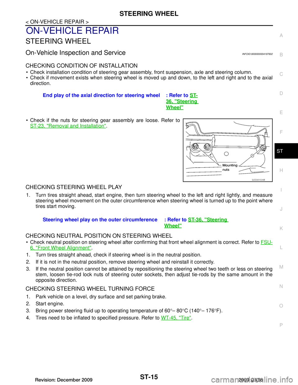
Check if the nuts for steering gear assembly are loose. Refer to ST-23, "Removal and Installation"
.
CHECKING STEERING WHEEL PLAY
1. Turn tires straight ahead, start engine, then turn steer ing wheel to the left and right lightly, and measure
steering wheel movement on the outer circumference when steering wheel is turned up to the point where
tires start moving.
CHECKING NEUTRAL POSITION ON STEERING WHEEL
Check neutral position on steering wheel after confirming that front wheel alignment is correct. Refer to FSU-
6, "Front Wheel Alignment".
1. Turn tires straight ahead, check if st eering wheel is in the neutral position.
2. If it is not in the neutral position, remo ve steering wheel and reinstall it correctly.
3. If the neutral position cannot be attained by repositi oning the steering wheel two teeth or less on steering
stem, loosen tie-rod lock nuts of steering outer socket s, then adjust tie-rods by the same amount in the
opposite direction.
CHECKING STEERING WHEEL TURNING FORCE
1. Park vehicle on a level, dry surface and set parking brake.
2. Start engine.
3. Bring power steering fluid up to operating temperature of 60 °– 80 °C (140 °– 176 °F).
4. Tires need to be inflated to specified pressure. Refer to WT-45, "Tire"
.
End play of the axial direction for steering wheel : Refer to
ST-
36, "Steering
Wheel"
LGIA0024E
Steering wheel play on the outer circumference : Refer to ST-36, "Steering
Wheel"
Revision: December 20092009 QX56
Page 3685 of 4171
DIAGNOSIS SYSTEM (TCM)TM-37
< FUNCTION DIAGNOSIS >
CEF
G H
I
J
K L
M A
B
TM
N
O P
Diagnosis Procedure without CONSULT-IIIINFOID:0000000004024115
OBD-II SELF-DIAGNOSTIC PROCEDURE (WITH GST)
Refer to EC-72, "Generic Scan Tool (GST) Function".
OBD-II SELF-DIAGNOSTIC PROCEDURE (NO TOOLS)
Refer to EC-55, "Malfunction Indicator Lamp (MIL)".
TCM SELF-DIAGNOSTIC PROCEDURE (NO TOOLS)
Description
When the ignition switch is switched “ON”, the A/T CHECK indicator lamp lights up for 2 seconds. As a method
for locating the suspect circuit, w hen the self-diagnostics start signal is input, the memory for the malfunction
location is output and the A/T CHECK indicator lamp flashes to display the corresponding DTC.
Diagnostic Procedure
1.CHECK A/T CHECK INDICATOR LAMP
1. Start the engine with selector lever in “P” pos ition. Warm engine to normal operating temperature.
2. Turn ignition switch ON and OFF at least twice, then leave it in the OFF position.
3. Wait 10 seconds.
4. Turn ignition switch ON. (Do not start engine.)
Does A/T CHECK indicator lamp come on for about 2 seconds?
YES >> GO TO 2.
NO >> GO TO TM-119, "A/T Check Indicator Lamp Does Not Come On"
.
2.JUDGEMENT PROCEDURE STEP 1
1. Turn ignition switch OFF.
2. Keep pressing shift lock release button.
3. Move selector lever from “P” to “D” position.
4. Release accelerator pedal. (Set the closed throttle position signal “ON”.)
5. Depress brake pedal. (Stop lamp switch signal “ON”.)
6. Turn ignition switch ON. (Do not start engine.)
7. Wait 3 seconds.
8. Move the selector lever from “D” to “3” position.
9. Release brake pedal. (Stop lamp switch signal “OFF”.)
10. Move the selector lever from “3” to “2” position.
11. Depress brake pedal. (Stop lamp switch signal “ON”.)
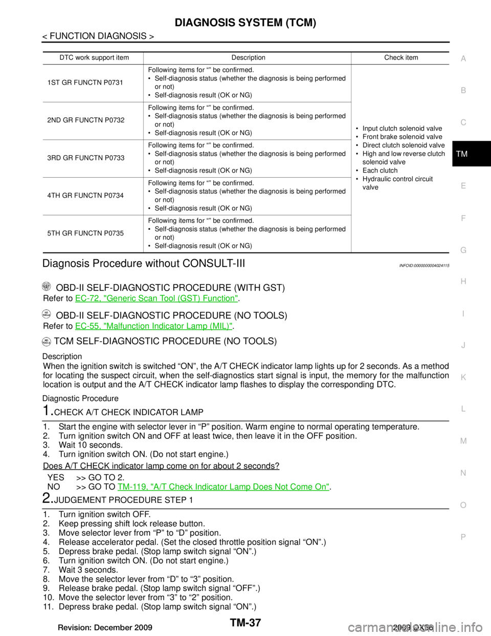
DTC work support item Description Check item
1ST GR FUNCTN P0731 Following items for “” be confirmed.
Self-diagnosis status (whether the diagnosis is being performed
or not)
Self-diagnosis result (OK or NG)
Input clutch solenoid valve
Front brake solenoid valve
Direct clutch solenoid valve
High and low reverse clutch solenoid valve
Each clutch
Hydraulic co ntrol circuit
valve
2ND GR FUNCTN P0732
Following items for “” be confirmed.
Self-diagnosis status (whether the diagnosis is being performed
or not)
Self-diagnosis result (OK or NG)
3RD GR FUNCTN P0733 Following items for “” be confirmed.
Self-diagnosis status (whether the diagnosis is being performed
or not)
Self-diagnosis result (OK or NG)
4TH GR FUNCTN P0734 Following items for “” be confirmed.
Self-diagnosis status (whether the diagnosis is being performed
or not)
Self-diagnosis result (OK or NG)
5TH GR FUNCTN P0735 Following items for “” be confirmed.
Self-diagnosis status (whether the diagnosis is being performed
or not)
Self-diagnosis result (OK or NG)
Revision: December 20092009 QX56
Page 3752 of 4171
TM-104
< ECU DIAGNOSIS >
TCM
ECU DIAGNOSIS
TCM
Reference ValueINFOID:0000000003771985
REFERENCE VALUES
NOTICE:
1. The CONSULT-III electrically displays shift timing and lock-up timing (that is, operation timing of each
solenoid).
Check for time difference between actual shift timi ng and the CONSULT-III display. If the difference is
noticeable, mechanical parts (except solenoids, sens ors, etc.) may be malfunctioning. Check mechanical
parts using applicable diagnostic procedures.
2. Shift schedule (which implies gear position) display ed on CONSULT-III and that indicated in Service Man-
ual may differ slightly. This occurs because of the following reasons:
- Actual shift schedule has more or less tolerance or allowance,
- Shift schedule indicated in Service Manual refers to the point where shifts start, and
- Gear position displayed on CONSULT-III indicates the point where shifts are completed.
3. Display of solenoid valves on CONSULT-III changes at t he start of shifting, while gear position is displayed
upon completion of shifting (which is computed by TCM).
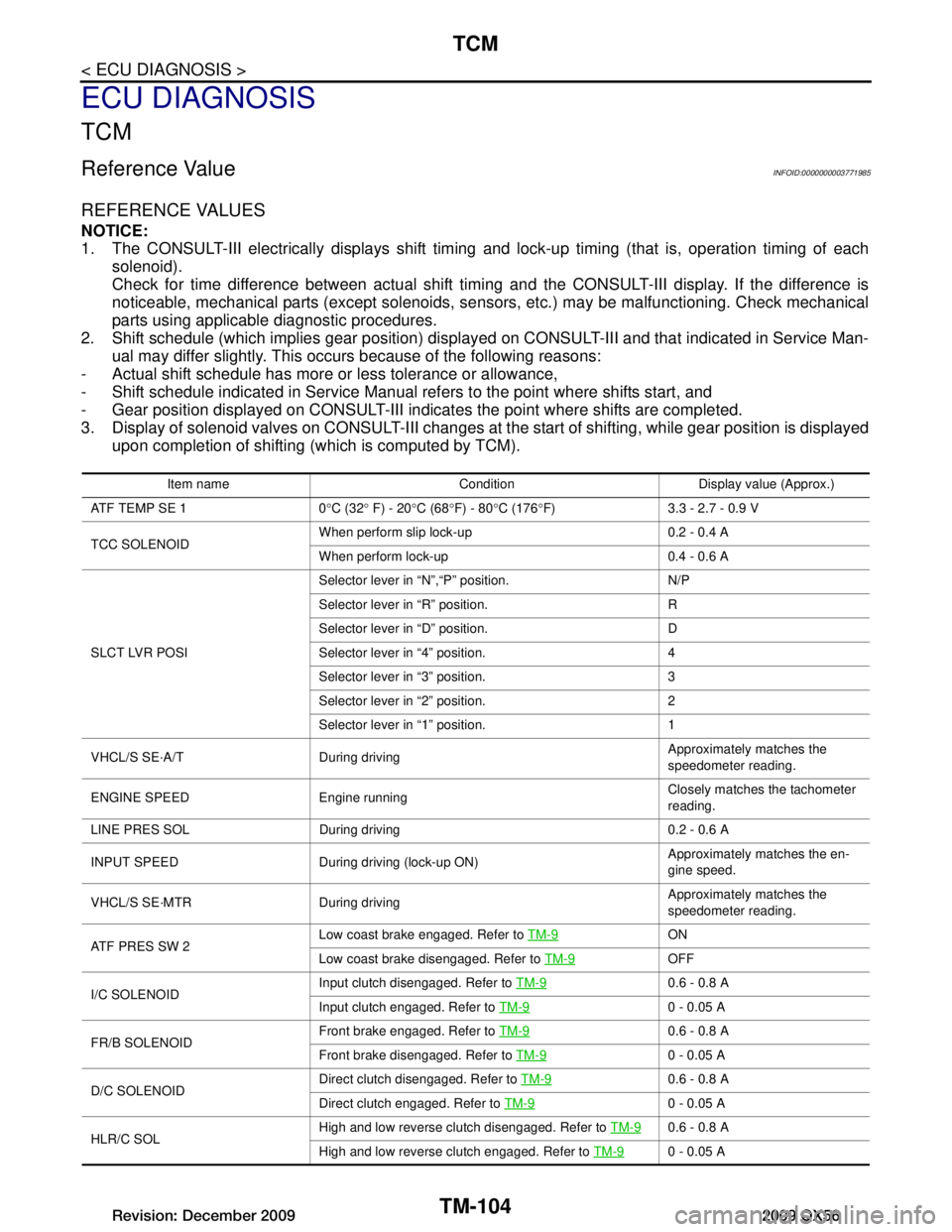
Item name Condition Display value (Approx.)
AT F T E M P S E 1 0 °C (32 ° F) - 20 °C (68 °F) - 80 °C (176 °F) 3.3 - 2.7 - 0.9 V
TCC SOLENOID When perform slip lock-up 0.2 - 0.4 A
When perform lock-up 0.4 - 0.6 A
SLCT LVR POSI Selector lever in “N”,“P” position. N/P
Selector lever in “R” position. R
Selector lever in “D” position. D
Selector lever in “4” position. 4
Selector lever in “3” position. 3
Selector lever in “2” position. 2
Selector lever in “1” position. 1
VHCL/S SE·A/T During driving Approximately matches the
speedometer reading.
ENGINE SPEED Engine running Closely matches the tachometer
reading.
LINE PRES SOL During driving 0.2 - 0.6 A
INPUT SPEED During driving (lock-up ON) Approximately matches the en-
gine speed.
VHCL/S SE·MTR During driving Approximately matches the
speedometer reading.
ATF PRES SW 2 Low coast brake engaged. Refer to
TM-9
ON
Low coast brake disengaged. Refer to TM-9
OFF
I/C SOLENOID Input clutch disengaged. Refer to
TM-9
0.6 - 0.8 A
Input clutch engaged. Refer to TM-9
0 - 0.05 A
FR/B SOLENOID Front brake engaged. Refer to
TM-9
0.6 - 0.8 A
Front brake disengaged. Refer to TM-9
0 - 0.05 A
D/C SOLENOID Direct clutch disengaged. Refer to
TM-9
0.6 - 0.8 A
Direct clutch engaged. Refer to TM-9
0 - 0.05 A
HLR/C SOL High and low reverse clutch disengaged. Refer to
TM-9
0.6 - 0.8 A
High and low reverse clutch engaged. Refer to TM-9
0 - 0.05 A
Revision: December 20092009 QX56
Page 3838 of 4171
TM-190
< ON-VEHICLE MAINTENANCE >
ROAD TEST
ROAD TEST
DescriptionINFOID:0000000003772026
ROAD TEST
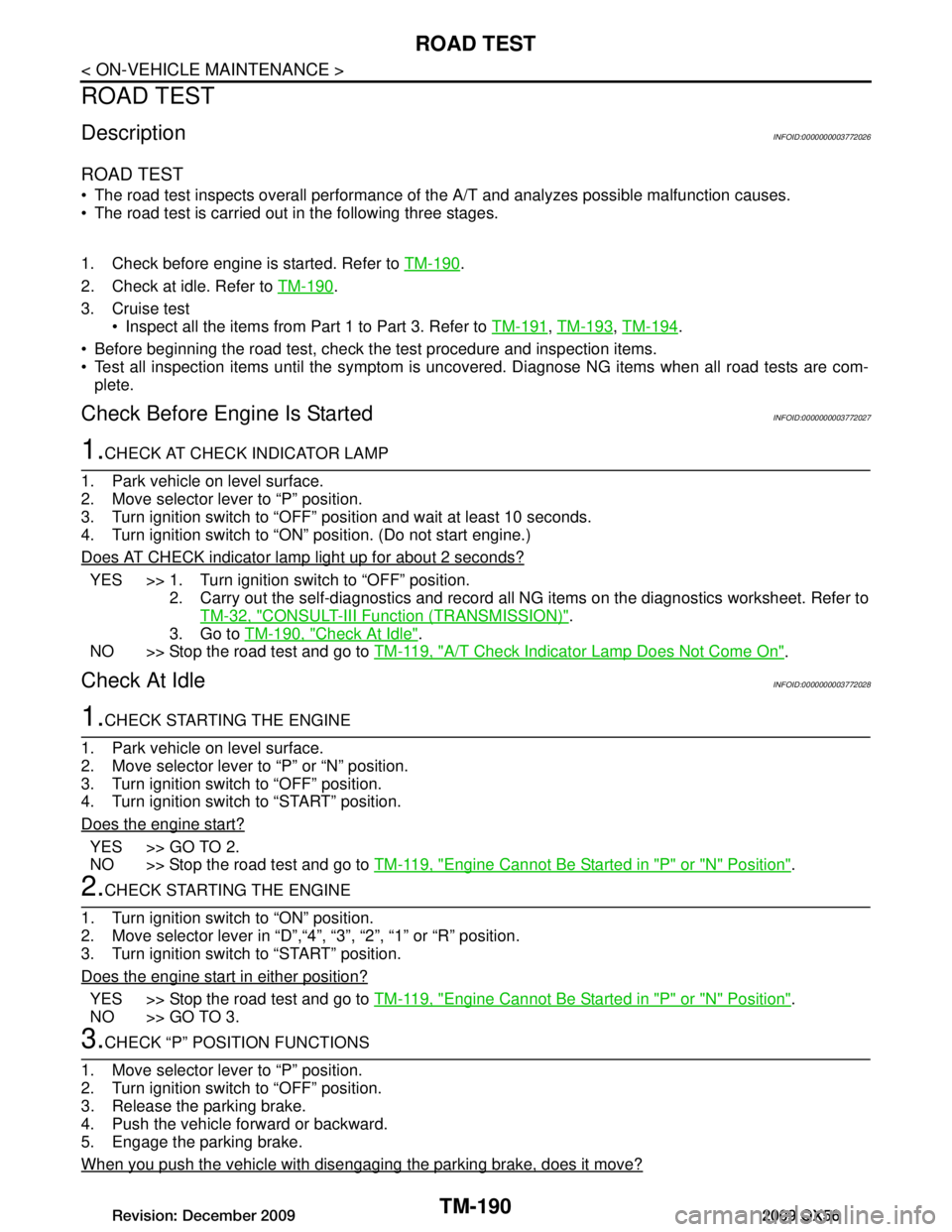
The road test inspects overall performance of the A/T and analyzes possible malfunction causes.
The road test is carried out in the following three stages.
1. Check before engine is started. Refer to TM-190
.
2. Check at idle. Refer to TM-190
.
3. Cruise test Inspect all the items from Part 1 to Part 3. Refer to TM-191
, TM-193, TM-194.
Before beginning the road test, check t he test procedure and inspection items.
Test all inspection items until the symptom is unc overed. Diagnose NG items when all road tests are com-
plete.
Check Before Engine Is StartedINFOID:0000000003772027
1.CHECK AT CHECK INDICATOR LAMP
1. Park vehicle on level surface.
2. Move selector lever to “P” position.
3. Turn ignition switch to “OFF” position and wait at least 10 seconds.
4. Turn ignition switch to “ON” position. (Do not start engine.)
Does AT CHECK indicator lamp light up for about 2 seconds?
YES >> 1. Turn ignition switch to “OFF” position. 2. Carry out the self-diagnostics and record al l NG items on the diagnostics worksheet. Refer to
TM-32, "CONSULT-III Function (TRANSMISSION)"
.
3. Go to TM-190, "Check At Idle"
.
NO >> Stop the road test and go to TM-119, "A/T Check Indicator Lamp Does Not Come On"
.
Check At IdleINFOID:0000000003772028
1.CHECK STARTING THE ENGINE
1. Park vehicle on level surface.
2. Move selector lever to “P” or “N” position.
3. Turn ignition switch to “OFF” position.
4. Turn ignition switch to “START” position.
Does the engine start?
YES >> GO TO 2.
NO >> Stop the road test and go to TM-119, "Engine Cannot Be Started in "P" or "N" Position"
.
2.CHECK STARTING THE ENGINE
1. Turn ignition switch to “ON” position.
2. Move selector lever in “D”,“4”, “3”, “2”, “1” or “R” position.
3. Turn ignition switch to “START” position.
Does the engine start in either position?
YES >> Stop the road test and go to TM-119, "Engine Cannot Be Started in "P" or "N" Position".
NO >> GO TO 3.
3.CHECK “P” POSITION FUNCTIONS
1. Move selector lever to “P” position.
2. Turn ignition switch to “OFF” position.
3. Release the parking brake.
4. Push the vehicle forward or backward.
5. Engage the parking brake.
When you push the vehicle with disengaging the parking brake, does it move?
Revision: December 20092009 QX56
Page 3841 of 4171
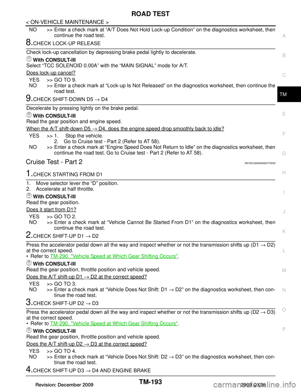
ROAD TESTTM-193
< ON-VEHICLE MAINTENANCE >
CEF
G H
I
J
K L
M A
B
TM
N
O P
NO >> Enter a check mark at “A/T Does Not Hold Lock-up Condition” on the diagnostics worksheet, then
continue the road test.
8.CHECK LOCK-UP RELEASE
Check lock-up cancellation by depressi ng brake pedal lightly to decelerate.
With CONSULT-III
Select “TCC SOLENOID 0.00A” with the “MAIN SIGNAL” mode for A/T.
Does lock-up cancel?
YES >> GO TO 9.
NO >> Enter a check mark at “Lock-up Is Not Rel eased” on the diagnostics worksheet, then continue the
road test.
9.CHECK SHIFT-DOWN D5 → D4
Decelerate by pressing lightly on the brake pedal. With CONSULT-III
Read the gear position and engine speed.
When the A/T shift-down D5
→ D4, does the engine speed drop smoothly back to idle?
YES >> 1. Stop the vehicle. 2. Go to Cruise test - Part 2 (Refer to AT 58).
NO >> Enter a check mark at “Engine Speed Does Not Return to Idle” on the diagnostics worksheet, then continue the road test. Go to Cruise test - Part 2 (Refer to AT 58).
Cruise Test - Part 2INFOID:0000000003772030
1.CHECK STARTING FROM D1
1. Move selector lever the “D” position.
2. Accelerate at half throttle. With CONSULT-III
Read the gear position.
Does it start from D1?
YES >> GO TO 2.
NO >> Enter a check mark at “Vehicle Cannot Be St arted From D1” on the diagnostics worksheet, then
continue the road test.
2.CHECK SHIFT-UP D1 → D2
Press the accelerator pedal down all the way and inspect whether or not the transmission shifts up (D1 → D2)
at the correct speed.
Refer to TM-290, "Vehicle Speed at Which Gear Shifting Occurs"
.
With CONSULT-III
Read the gear position, thrott le position and vehicle speed.
Does the A/T shift-up D1
→ D2 at the correct speed?
YES >> GO TO 3.
NO >> Enter a check mark at “Vehicle Does Not Shift: D1 → D2” on the diagnostics worksheet, then con-
tinue the road test.
3.CHECK SHIFT-UP D2 → D3
Press the accelerator pedal down all the way and inspect whether or not the transmission shifts up (D2 → D3)
at the correct speed.
Refer to TM-290, "Vehicle Speed at Which Gear Shifting Occurs"
.
With CONSULT-III
Read the gear position, thrott le position and vehicle speed.
Does the A/T shift-up D2
→ D3 at the correct speed?
YES >> GO TO 4.
NO >> Enter a check mark at “Vehicle Does Not Shift: D2 → D3” on the diagnostics worksheet, then con-
tinue the road test.
4.CHECK SHIFT-UP D3 → D4 AND ENGINE BRAKE
Revision: December 20092009 QX56
Page 3919 of 4171
ASSEMBLYTM-271
< DISASSEMBLY AND ASSEMBLY >
CEF
G H
I
J
K L
M A
B
TM
N
O P
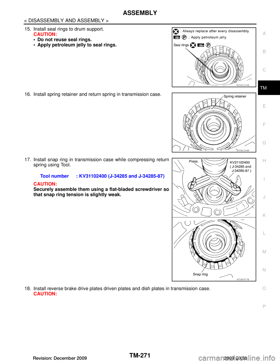
15. Install seal rings to drum support. CAUTION:
Do not reuse seal rings.
Apply petroleum jelly to seal rings.
16. Install spring retainer and return spring in transmission case.
17. Install snap ring in transmission case while compressing return spring using Tool.
CAUTION:
Securely assemble them using a flat-bladed screwdriver so
that snap ring tension is slightly weak.
18. Install reverse brake drive plates driven pl ates and dish plates in transmission case.
CAUTION:
SCIA3333E
SCIA2324E
Tool number : KV31102400 (J-34285 and J-34285-87)
SCIA5877E
Revision: December 20092009 QX56
Page 3990 of 4171

WCS
DIAGNOSIS SYSTEM (METER)WCS-13
< FUNCTION DIAGNOSIS >
C
DE
F
G H
I
J
K L
M B A
O P
NOTE:
Some items are not available due to vehicle specification.
*: The monitor will indicate “OFF” even though the brake warnin g lamp is on if either of the following conditions exist.
• The parking brake is engaged
• The brake fluid level is low AT SFT DWN SW [ON/OFF]
XX Displays [ON/O FF] condition of A/T shift-down switch.
DISTANCE [km] or [mile] XXDisplays the value, which is calculated by vehicle speed signal, fuel
gauge and fuel consumption from ECM.
BUZZER [ON/OFF] XX Displays [ON/ OFF] condition of buzzer.
BRAKE SW [ON/OFF] X Indicates [ON/OFF] condition of parking brake switch.
AT-M GEAR [1, 2, 3, 4, 5] XX Indicates [1, 2, 3, 4, 5] condition of A/T manual mode gear position.
P RANGE IND [ON/OFF] XX Indicates [ON/OFF] condition of A/T shift P range indicator.
R RANGE IND [ON/OFF] XX Indicates [ON/OFF] condition of A/T shift R range indicator.
N RANGE IND [ON/OFF] XX Indicates [ON/OFF] condition of A/T shift N range indicator.
D RANGE IND [ON/OFF] XX Indicates [ON/OFF] condition of A/T shift D range indicator.
4 RANGE IND [ON/OFF] XX Indicates [ON/OFF] condition of A/T shift 4 range indicator.
3 RANGE IND [ON/OFF] XX Indicates [ON/OFF] condition of A/T shift 3 range indicator.
2 RANGE IND [ON/OFF] XX Indicates [ON/OFF] condition of A/T shift 2 range indicator.
1 RANGE IND [ON/OFF] XX Indicates [ON/OFF] condition of A/T shift 1range indicator.
CRUISE W/L [ON/OFF] X Indicates [ON/OFF] condition of CRUISE warning lamp.
4WD LOCK SW [ON/OFF] X Indicates [ON/OFF] condition of 4WD lock switch.
4WD LOCK IND [ON/OFF] X Indicates [ON/OFF] condition of 4WD lock indicator.
SEAT BELT W/L [ON/OFF] X Indicates [ON/OFF] condition of seat belt warning lamp.
FR FOG IND [ON/OFF] X This item is not used for this model. “OFF” is always displayed.
RR FOG IND [ON/OFF] X This item is not used for this model. “OFF” is always displayed.
LIGHT IND [ON/OFF] X Indicates [ON/OFF] condition of light indicator.
PNP P SW [ON/OFF] XX Indicates [ON/OFF] condition of park/neutral position P switch.
PNP N SW [ON/OFF] XX Indicates [ON/OFF] condition of park/neutral position N switch.
4WD W/L [ON/OFF] X Indicates [ON/OFF] condition of 4WD warning lamp.
Display item [Unit]
MAIN
SIGNALS SELECTION
FROM MENU Description
Revision: December 20092009 QX56