2009 INFINITI QX56 lock
[x] Cancel search: lockPage 2615 of 4171
![INFINITI QX56 2009 Factory Service Manual LAN-46
< FUNCTION DIAGNOSIS >[CAN]
CAN COMMUNICATION SYSTEM
NOTE:
CAN data of the air bag diagnosis sensor unit is not us
ed by usual service work, thus it is omitted.
Tire pressure data signal R T
T INFINITI QX56 2009 Factory Service Manual LAN-46
< FUNCTION DIAGNOSIS >[CAN]
CAN COMMUNICATION SYSTEM
NOTE:
CAN data of the air bag diagnosis sensor unit is not us
ed by usual service work, thus it is omitted.
Tire pressure data signal R T
T](/manual-img/42/57031/w960_57031-2614.png)
LAN-46
< FUNCTION DIAGNOSIS >[CAN]
CAN COMMUNICATION SYSTEM
NOTE:
CAN data of the air bag diagnosis sensor unit is not us
ed by usual service work, thus it is omitted.
Tire pressure data signal R T
Tire pressure signal R TR
Turn indicator signal TR
Buzzer output signal TR
Door lock/unlock request signal RT
Hazard request signal RT
Hazard warning lamp request signal RT
Ignition knob switch signal RT
KEY warning signal TR
LOCK warning signal TR
Panic alarm request signal RT
Power window open request signal RT
1st position switch signal R T
4th position switch signal R T
Distance to empty signal RT
Fuel level low warning signal RT
Fuel level sensor signal R T
Parking brake switch signal RT
Seat belt buckle switch signal RT
Stop lamp switch signal R T
Tow mode switch signal R T
Vehicle speed signal RRR RRR R T
RRRT
Steering angle sensor signal TR
ABS malfunction signal RT
ABS warning lamp signal RT
Brake pressure sensor signal RT
Brake warning lamp signal RT
SLIP indicator lamp signal RT
TCS malfunction signal RT
VDC malfunction signal RT
VDC OFF indicator lamp signal RRT
VDC operation signal RT
Front wiper stop position signal RT
High beam status signal R T
Hood switch signal RT
Low beam status signal R T
Rear window defogger control signal R RT
Signal name/Connecting unit
ECM
TCM
LASER ICC
ADP
AV
BCM
HVAC I-KEY M&A
STRG 4WDABS
IPDM-E
Revision: December 20092009 QX56
Page 2657 of 4171
LU-2
< PRECAUTION >
PRECAUTIONS
PRECAUTION
PRECAUTIONS
Precaution for Supplemental Restraint System (SRS) "AIR BAG" and "SEAT BELT
PRE-TENSIONER"
INFOID:0000000005851889
The Supplemental Restraint System such as “A IR BAG” and “SEAT BELT PRE-TENSIONER”, used along
with a front seat belt, helps to reduce the risk or severity of injury to the driver and front passenger for certain
types of collision. This system includes seat belt switch inputs and dual stage front air bag modules. The SRS
system uses the seat belt switches to determine the front air bag deployment, and may only deploy one front
air bag, depending on the severity of a collision and w hether the front occupants are belted or unbelted.
Information necessary to service the system safely is included in the SR and SB section of this Service Man-
ual.
WARNING:
• To avoid rendering the SRS inopera tive, which could increase the risk of personal injury or death in
the event of a collision which would result in air bag inflation, all maintenance must be performed by
an authorized NISSAN/INFINITI dealer.
• Improper maintenance, including in correct removal and installation of the SRS, can lead to personal
injury caused by unintent ional activation of the system. For re moval of Spiral Cable and Air Bag
Module, see the SR section.
• Do not use electrical test equipmen t on any circuit related to the SRS unless instructed to in this
Service Manual. SRS wiring harn esses can be identified by yellow and/or orange harnesses or har-
ness connectors.
PRECAUTIONS WHEN USING POWER TOOLS (AIR OR ELECTRIC) AND HAMMERS
WARNING:
• When working near the Airbag Diagnosis Sensor Unit or other Airbag System sensors with the Igni-
tion ON or engine running, DO NOT use air or electri c power tools or strike near the sensor(s) with a
hammer. Heavy vibration could activate the sensor( s) and deploy the air bag(s), possibly causing
serious injury.
• When using air or electric power tools or hammers , always switch the Ignition OFF, disconnect the
battery, and wait at least 3 minu tes before performing any service.
Precaution Necessary for Steering W heel Rotation After Battery Disconnect
INFOID:0000000005851890
NOTE:
• This Procedure is applied only to models with Intelligent Key system and NATS (NISSAN ANTI-THEFT SYS-
TEM).
• Remove and install all control units after disconnecting both battery cables with the ignition knob in the
″LOCK ″ position.
• Always use CONSULT-III to perform self-diagnosis as a part of each function inspection after finishing work.
If DTC is detected, perform trouble diagnosis according to self-diagnostic results.
For models equipped with the Intelligent Key system and NATS, an electrically controlled steering lock mech-
anism is adopted on the key cylinder.
For this reason, if the battery is disconnected or if the battery is discharged, the steering wheel will lock and
steering wheel rotation will become impossible.
If steering wheel rotation is required when battery pow er is interrupted, follow the procedure below before
starting the repair operation.
OPERATION PROCEDURE
1. Connect both battery cables. NOTE:
Supply power using jumper cables if battery is discharged.
2. Use the Intelligent Key or mechanical key to turn the ignition switch to the ″ACC ″ position. At this time, the
steering lock will be released.
3. Disconnect both battery cables. The steering lock will remain released and the steering wheel can be rotated.
4. Perform the necessary repair operation.
Revision: December 20092009 QX56
Page 2658 of 4171
PRECAUTIONSLU-3
< PRECAUTION >
C
DE
F
G H
I
J
K L
M A
LU
NP
O
5. When the repair work is completed, return the ignition switch to the
″LOCK ″ position before connecting
the battery cables. (At this time, the steering lock mechanism will engage.)
6. Perform a self-diagnosis check of al l control units using CONSULT-III.
Precaution for Liquid GasketINFOID:0000000003771265
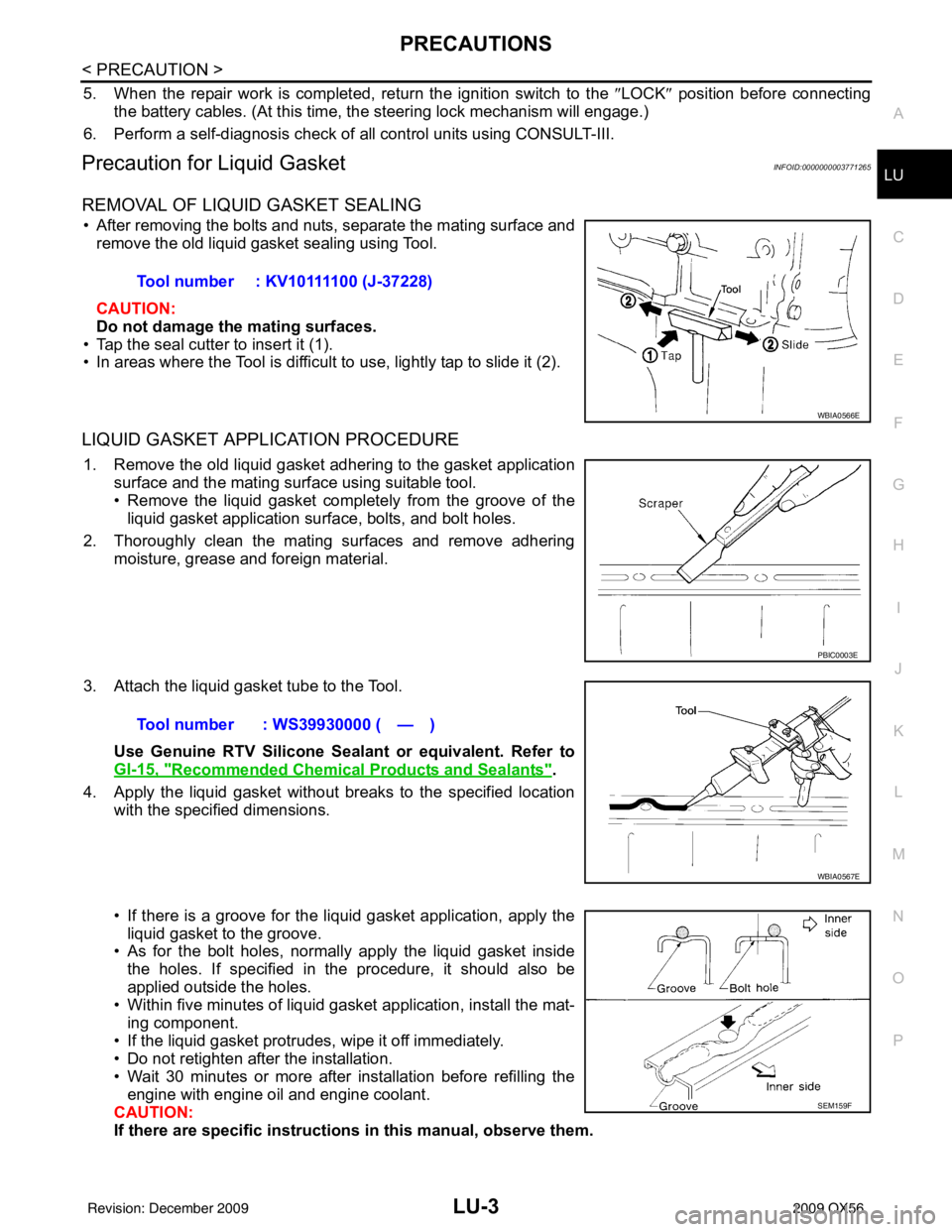
REMOVAL OF LIQUID GASKET SEALING
• After removing the bolts and nuts, separate the mating surface and
remove the old liquid gasket sealing using Tool.
CAUTION:
Do not damage the mating surfaces.
• Tap the seal cutter to insert it (1).
• In areas where the Tool is difficult to use, lightly tap to slide it (2).
LIQUID GASKET APPLICATION PROCEDURE
1. Remove the old liquid gasket adhering to the gasket application surface and the mating surface using suitable tool.
• Remove the liquid gasket completely from the groove of the
liquid gasket application surface, bolts, and bolt holes.
2. Thoroughly clean the mating surfaces and remove adhering moisture, grease and foreign material.
3. Attach the liquid gasket tube to the Tool. Use Genuine RTV Silicone Sealant or equivalent. Refer to
GI-15, "
Recommended Chemical Products and Sealants".
4. Apply the liquid gasket without breaks to the specified location with the specified dimensions.
• If there is a groove for the liquid gasket application, apply theliquid gasket to the groove.
• As for the bolt holes, normally apply the liquid gasket inside
the holes. If specified in the procedure, it should also be
applied outside the holes.
• Within five minutes of liquid gasket application, install the mat-
ing component.
• If the liquid gasket protrudes, wipe it off immediately.
• Do not retighten after the installation.
• Wait 30 minutes or more after installation before refilling the engine with engine oil and engine coolant.
CAUTION:
If there are specific instructions in this manual, observe them.
Tool number : KV10111100 (J-37228)
WBIA0566E
PBIC0003E
Tool number : WS39930000 ( — )
WBIA0567E
SEM159F
Revision: December 20092009 QX56
Page 2659 of 4171
LU-4
< PREPARATION >
PREPARATION
PREPARATION
PREPARATION
Special Service ToolINFOID:0000000003771266
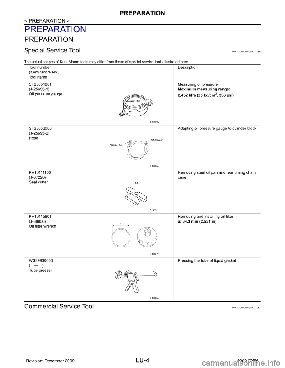
The actual shapes of Kent-Moore tools may differ from those of special service tools illustrated here.
Commercial Service ToolINFOID:0000000003771267
Tool number
(Kent-Moore No.)
Tool name Description
ST25051001
(J-25695-1)
Oil pressure gauge Measuring oil pressure
Maximum measuring range:
2,452 kPa (25 kg/cm
2, 356 psi)
ST25052000
(J-25695-2)
Hose Adapting oil pressure gauge to cylinder block
K V 1 0 1111 0 0
(J-37228)
Seal cutter Removing steel oil pan and rear timing chain
case
KV10115801
(J-38956)
Oil filter wrench Removing and installing oil filter
a: 64.3 mm (2.531 in)
WS39930000
(—)
Tube presser Pressing the tube of liquid gasket
S-NT050
S-NT559
NT046
S-NT375
S-NT052
Revision: December 20092009 QX56
Page 2663 of 4171

LU-8
< ON-VEHICLE MAINTENANCE >
ENGINE OIL
ON-VEHICLE MAINTENANCE
ENGINE OIL
InspectionINFOID:0000000003771270
OIL LEVEL
• Before starting the engine make sure the vehicle is parked on a flatand level surface, then check the oil level. If the engine is already
running, turn it off and allow 10 minutes before checking.
• Check that the oil level is within the low (L) and high (H) range as indicated on the dipstick.
• If the engine oil level is out of range, add oil as necessary. Refer to
MA-12, "
Fluids and Lubricants".
OIL APPEARANCE
• Check the engine oil for a white milky appearance or excessive contamination.
• If the engine oil is milky, it is highly probable that it is contaminated with engine coolant. Repair the broken
parts.
OIL LEAKAGE
Check for oil leakage around the following areas:
•Oil pan
• Oil pan drain plug
• Oil pressure switch
• Oil filter
• Oil cooler
• Intake valve timing control cover
• Intake valve timing control solenoid valve
• Front cover
• Mating surface between cylinder block and cylinder head
• Mating surface between cylinder head and rocker cover
• Crankshaft oil seal (front and rear)
OIL PRESSURE CHECK
WARNING:
• Be careful not to burn yoursel f, as engine oil may be hot.
• Put the A/T shift selector in the Park “P” position.
1. Check the engine oil level. Refer to LU-8, "
Inspection".
2. Remove engine front undercover using power tool.
3. Disconnect the oil pressure switch harness connector.
4. Remove the oil pressure switch (A).
SMA954C
WBIA0791E
Revision: December 20092009 QX56
Page 2664 of 4171
ENGINE OILLU-9
< ON-VEHICLE MAINTENANCE >
C
DE
F
G H
I
J
K L
M A
LU
NP
O
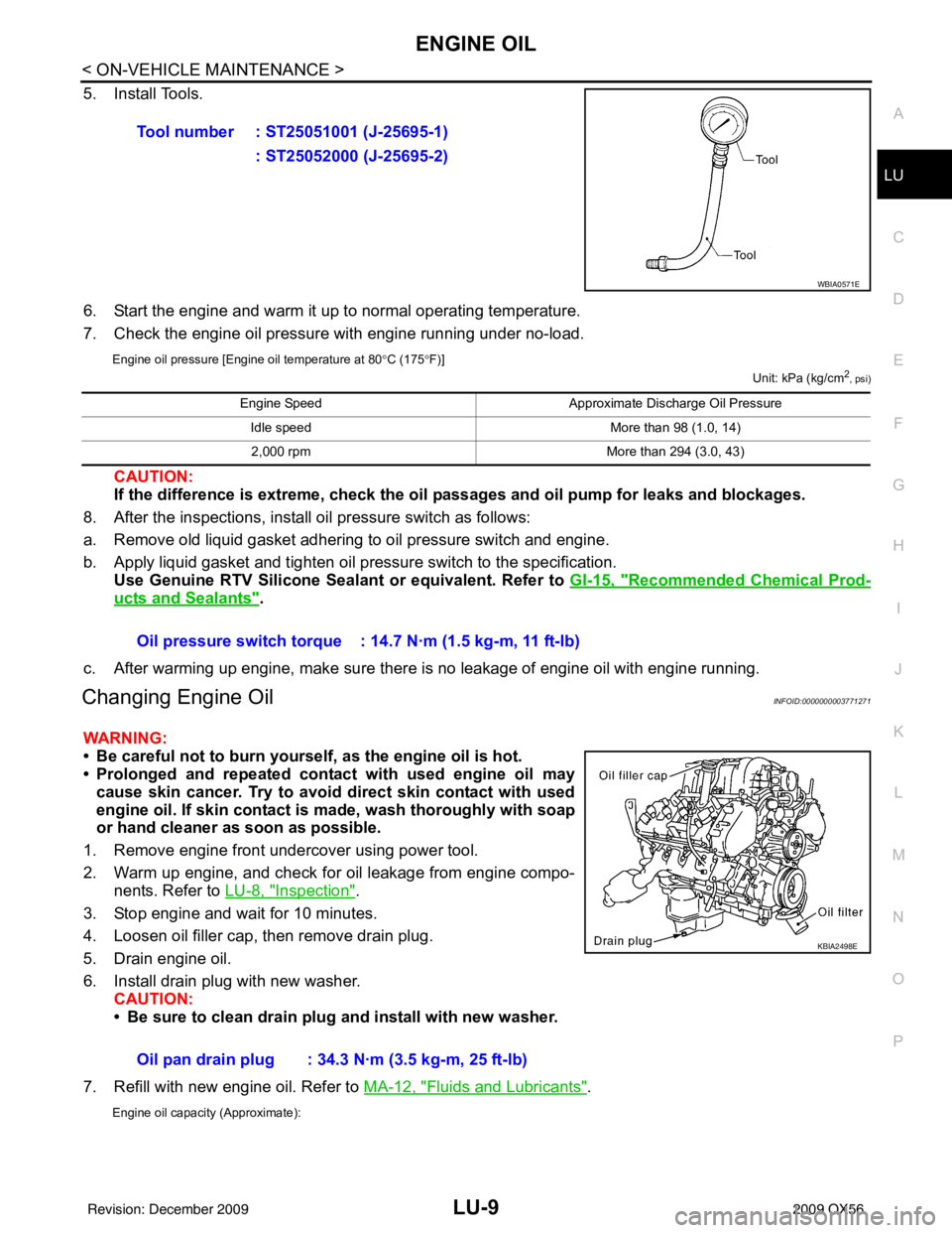
5. Install Tools.
6. Start the engine and warm it up to normal operating temperature.
7. Check the engine oil pressure with engine running under no-load.
Engine oil pressure [Engine oil temperature at 80
°C (175 °F)]
Unit: kPa (kg/cm2, psi)
CAUTION:
If the difference is extreme, check the oil passages and oil pump for leaks and blockages.
8. After the inspections, install oil pressure switch as follows:
a. Remove old liquid gasket adhering to oil pressure switch and engine.
b. Apply liquid gasket and tighten oil pressure switch to the specification. Use Genuine RTV Silicone Seal ant or equivalent. Refer to GI-15, "
Recommended Chemical Prod-
ucts and Sealants".
c. After warming up engine, make sure there is no leakage of engine oil with engine running.
Changing Engine OilINFOID:0000000003771271
WARNING:
• Be careful not to burn yourself, as the engine oil is hot.
• Prolonged and repeated contact with used engine oil may cause skin cancer. Try to avoid direct skin contact with used
engine oil. If skin contact is made, wash thoroughly with soap
or hand cleaner as soon as possible.
1. Remove engine front undercover using power tool.
2. Warm up engine, and check for oil leakage from engine compo- nents. Refer to LU-8, "
Inspection".
3. Stop engine and wait for 10 minutes.
4. Loosen oil filler cap, then remove drain plug.
5. Drain engine oil.
6. Install drain plug with new washer. CAUTION:
• Be sure to clean drain plug and install with new washer.
7. Refill with new engine oil. Refer to MA-12, "
Fluids and Lubricants".
Engine oil capacity (Approximate):
Tool number : ST25051001 (J-25695-1)
: ST25052000 (J-25695-2)
WBIA0571E
Engine Speed Approximate Discharge Oil Pressure
Idle speed More than 98 (1.0, 14)
2,000 rpm More than 294 (3.0, 43)
Oil pressure switch torque : 14.7 N·m (1.5 kg-m, 11 ft-lb)
Oil pan drain plug : 34.3 N·m (3.5 kg-m, 25 ft-lb)
KBIA2498E
Revision: December 20092009 QX56
Page 2667 of 4171
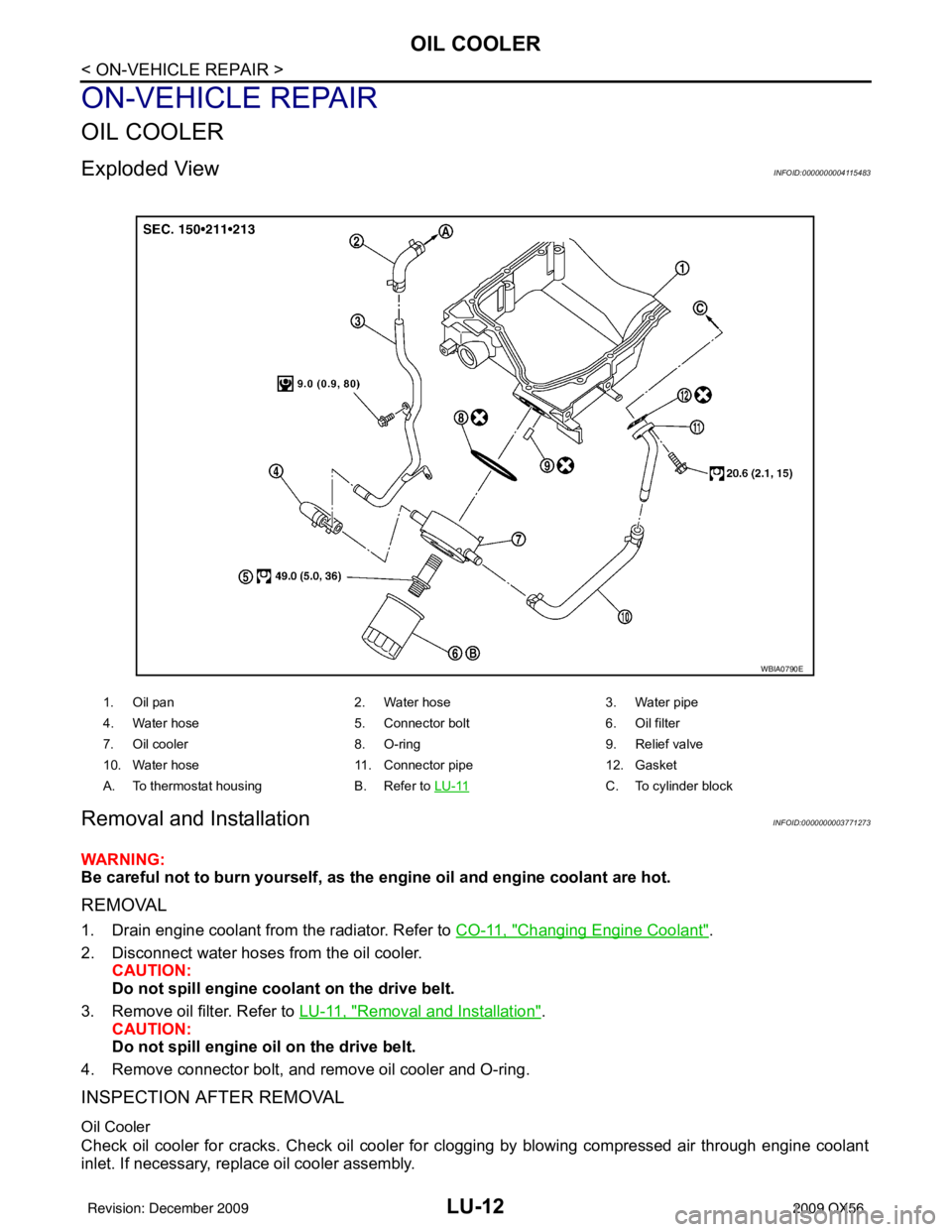
LU-12
< ON-VEHICLE REPAIR >
OIL COOLER
ON-VEHICLE REPAIR
OIL COOLER
Exploded ViewINFOID:0000000004115483
Removal and InstallationINFOID:0000000003771273
WARNING:
Be careful not to burn yourself, as the engine oil and engine coolant are hot.
REMOVAL
1. Drain engine coolant from the radiator. Refer to CO-11, "Changing Engine Coolant".
2. Disconnect water hoses from the oil cooler. CAUTION:
Do not spill engine coolant on the drive belt.
3. Remove oil filter. Refer to LU-11, "
Removal and Installation".
CAUTION:
Do not spill engine oil on the drive belt.
4. Remove connector bolt, and remove oil cooler and O-ring.
INSPECTION AFTER REMOVAL
Oil Cooler
Check oil cooler for cracks. Check oil cooler for clogging by blowing compressed air through engine coolant
inlet. If necessary, replace oil cooler assembly.
1. Oil pan 2. Water hose3. Water pipe
4. Water hose 5. Connector bolt 6. Oil filter
7. Oil cooler 8. O-ring 9. Relief valve
10. Water hose 11. Connector pipe 12. Gasket
A. To thermostat housing B. Refer to LU-11
C. To cylinder block
WBIA0790E
Revision: December 20092009 QX56
Page 2674 of 4171

MA-1
MAINTENANCE
C
DE
F
G H
I
J
K L
M B
MA
SECTION MA
N
O A
CONTENTS
MAINTENANCE
PRECAUTION .......
........................................2
PRECAUTIONS .............................................. .....2
Precaution for Supplemental Restraint System
(SRS) "AIR BAG" and "SEAT BELT PRE-TEN-
SIONER" ............................................................. ......
2
Precaution Necessary for Steering Wheel Rota-
tion After Battery Disconnect ............................... ......
2
PREPARATION ............................................4
PREPARATION .............................................. .....4
Special Service Tool ........................................... ......4
Commercial Service Tool ..........................................4
ON-VEHICLE MAINTENANCE .....................6
GENERAL MAINTE NANCE ........................... .....6
General Maintenance .......................................... ......6
PERIODIC MAINTENANCE ................................8
Introduction of Periodic Maintenance .................. ......8
Maintenance for Off-road Driving (4WD only) ...........8
Schedule 1 ................................................................8
Schedule 2 ..............................................................10
RECOMMENDED FLUIDS AND LUBRI-
CANTS ................................................................
12
Fluids and Lubricants .......................................... ....12
Engine Oil Recommendation ..................................13
ENGINE MAINTENANCE ...................................14
Checking Drive Belts ........................................... ....14
Changing Engine Coolant .......................................14
Checking Fuel Line .............................................. ....17
Changing Fuel Filter ................................................17
Changing Engine Air Cleaner Filter .........................17
Changing Engine Oil ................................................18
Changing Oil Filter ...................................................18
Changing Spark Plugs .............................................19
Checking EVAP Vapor Line .....................................20
CHASSIS AND BODY MAINTENANCE ...........22
Changing In-cabin Microfilter ............................... ....22
Checking Exhaust System .......................................22
Checking the A/T Fluid (ATF) ..................................23
Changing the A/T Fluid (ATF) ..................................24
Checking Transfer Fluid ..........................................25
Changing Transfer Fluid ..........................................26
Checking Propeller Shaft .........................................26
Checking Front Final Drive Oil .................................26
Changing Front Final Drive Oil ................................27
Checking Rear Final Drive Oil .................................27
Changing Rear Final Drive Oil .................................27
Balancing Wheels ....................................................28
Rotation ...................................................................29
Checking Brake Fluid Level and Leaks ...................30
Checking Brake Line and Cables ............................30
Checking Disc Brake ...............................................30
Checking Steering Gear and Linkage ......................31
Checking Power Steering Fluid and Line ................31
Checking Axle and Suspension Parts .....................32
Lubricating Locks, Hinges and Hood Latches .........33
Checking Seat Belts, Buckles, Retractors, An-
chors and Adjusters ............................................. ....
33
Revision: December 20092009 QX56