Page 3948 of 4171
VTL-8
< ON-VEHICLE REPAIR >
CONTROL UNIT
2. Remove the three screws (A) and remove the rear air control(rear) (1).
Installation
Installation is in the reverse order of removal.
ALIIA0059ZZ
Revision: December 20092009 QX56
Page 3949 of 4171
IN-VEHICLE SENSORVTL-9
< ON-VEHICLE REPAIR >
C
DE
F
G H
J
K L
M A
B
VTL
N
O P
IN-VEHICLE SENSOR
Removal and InstallationINFOID:0000000003775262
REMOVAL
1. Remove the lower instrument panel LH. Refer to IP-12, "Exploded View".
2. Remove the two screws (A) and remove the in-vehicle sensor (1).
INSTALLATION
Installation is in the reverse order of removal.
ALIIA0060ZZ
Revision: December 20092009 QX56
Page 3950 of 4171
VTL-10
< ON-VEHICLE REPAIR >
OPTICAL SENSOR
OPTICAL SENSOR
Removal and InstallationINFOID:0000000003775263
REMOVAL
1. Remove the defroster grille from the instrument panel. Refer to VTL-33, "Removal and Installation".
2. Disconnect the optical sensor connector (2).
3. Twist the optical sensor (1) counter clockwise to remove it from the defroster grille.
INSTALLATION
Installation is in the reverse order of removal.
ALIIA0061ZZ
Revision: December 20092009 QX56
Page 3951 of 4171
INTAKE SENSORVTL-11
< ON-VEHICLE REPAIR >
C
DE
F
G H
J
K L
M A
B
VTL
N
O P
INTAKE SENSOR
Removal and InstallationINFOID:0000000003775264
REMOVAL
1. Remove the instrument lower panel RH and glove box. Refer to IP-17, "Removal and Installation".
2. Disconnect the intake sensor electrical connector. NOTE:
The intake sensor is located on the top of the front heater and
cooling unit assembly next to the A/C evaporator cover.
3. Twist the intake sensor to remove the intake sensor from the front heater and cooling unit assembly.
INSTALLATION
Installation is in the reverse order of removal.
LJIA0133E
Revision: December 20092009 QX56
Page 3952 of 4171
VTL-12
< ON-VEHICLE REPAIR >
BLOWER MOTOR
BLOWER MOTOR
ComponentINFOID:0000000003775265
Front Blower MotorRear Blower Motor
Removal and InstallationINFOID:0000000003775266
FRONT BLOWER MOTOR
Removal
1. Remove the instrument lower panel RH and glove box assembly. Refer to IP-17, "Removal and Installa-
tion".
2. Disconnect the front blower motor electrical connector.
3. Remove the three screws and remove the front blower motor.
4. Remove blower motor wheel as necessary to transfer to new blower motor.
Installation
LJIA0136E
1. Front heater and cooling unit assembly 2. Front blower motor 3. Front variable blower control
AWIIA0085ZZ
1. Rear blower motor2. Rear heater and cooling unit assembly 3. Rear variable blower control
Revision: December 20092009 QX56
Page 3953 of 4171
BLOWER MOTORVTL-13
< ON-VEHICLE REPAIR >
C
DE
F
G H
J
K L
M A
B
VTL
N
O P
Installation is in the reverse order of removal.
REAR BLOWER MOTOR
Removal
1. Remove the rear heater and cooling unit assembly. Refer to VTL-16, "Removal and Installation".
2. Disconnect the rear blower motor electrical connector.
3. Remove the three screws and remove the rear blower motor.
4. Remove blower motor wheel as necessary to transfer to new blower motor.
Installation
Installation is in the reverse order of removal.
Revision: December 20092009 QX56
Page 3954 of 4171

VTL-14
< ON-VEHICLE REPAIR >
IN-CABIN MICROFILTER
IN-CABIN MICROFILTER
Removal and InstallationINFOID:0000000003775267
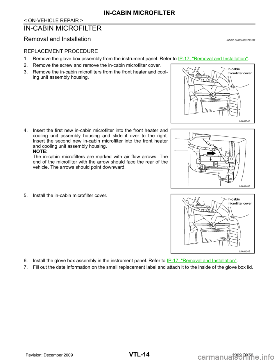
REPLACEMENT PROCEDURE
1. Remove the glove box assembly from the instrument panel. Refer to IP-17, "Removal and Installation".
2. Remove the screw and remove the in-cabin microfilter cover.
3. Remove the in-cabin microfilters from the front heater and cool- ing unit assembly housing.
4. Insert the first new in-cabin micr ofilter into the front heater and
cooling unit assembly housing and slide it over to the right.
Insert the second new in-cabin mi crofilter into the front heater
and cooling unit assembly housing.
NOTE:
The in-cabin microfilters are marked with air flow arrows. The
end of the microfilter with the arro w should face the rear of the
vehicle. The arrows should point downward.
5. Install the in-cabin microfilter cover.
6. Install the glove box assembly in the instrument panel. Refer to IP-17, "
Removal and Installation".
7. Fill out the date information on the sm all replacement label and attach it to the inside of the glove box lid.
LJIA0134E
LJIA0148E
LJIA0134E
Revision: December 20092009 QX56
Page 3955 of 4171
HEATER & COOLING UNIT ASSEMBLYVTL-15
< ON-VEHICLE REPAIR >
C
DE
F
G H
J
K L
M A
B
VTL
N
O P
HEATER & COOLING UNIT ASSEMBLY
ComponentINFOID:0000000003775268
Front A/C System
ALIIA0402ZZ
1. High-pressure service valve 2. Grommet 3. High-pressure pipe
4. Refrigerant pressure sensor 5. Condenser 6. Compressor shaft seal
7. High-pressure flexible hose 8. Low-pressure flexible hose 9. Low-pressure service valve
Revision: December 20092009 QX56