2009 INFINITI QX56 check engine
[x] Cancel search: check enginePage 2874 of 4171
PG
PRECAUTIONSPG-3
< PRECAUTION >
C
DE
F
G H
I
J
K L
B A
O P
N
5. When the repair work is completed, return the ignition switch to the
″LOCK ″ position before connecting
the battery cables. (At this time, the steering lock mechanism will engage.)
6. Perform a self-diagnosis check of al l control units using CONSULT-III.
Precaution for Power Generation Variable Voltage Control SystemINFOID:0000000003776561
CAUTION:
For this model, the battery current sensor that is installed to the negative battery cable measures the
charging/discharging current of the battery and performs various engine controls. If an electrical com-
ponent is connected directly to the negative battery terminal, the current flowing through that compo-
nent will not be measured by the battery current sensor. This condition may cause a malfunction of
the engine control system and battery discharge m ay occur. Do not connect an electrical component
or ground wire directly to the battery terminal.
Revision: December 20092009 QX56
Page 2876 of 4171
PG
BATTERYPG-5
< BASIC INSPECTION >
C
DE
F
G H
I
J
K L
B A
O P
N
BASIC INSPECTION
BATTERY
How to Handle BatteryINFOID:0000000003776564
CAUTION:
• If it becomes necessary to start the engine with
a booster battery and jumper cables, use a 12-volt
booster battery.
• After connecting battery cables, ensure that they are tightly clamped to battery terminals for good
contact.
• Never add distilled water through the hole used to check specific gravity.
METHODS OF PREVENTING OVER-DISCHARGE
The following precautions must be taken to prevent over-discharging a battery.
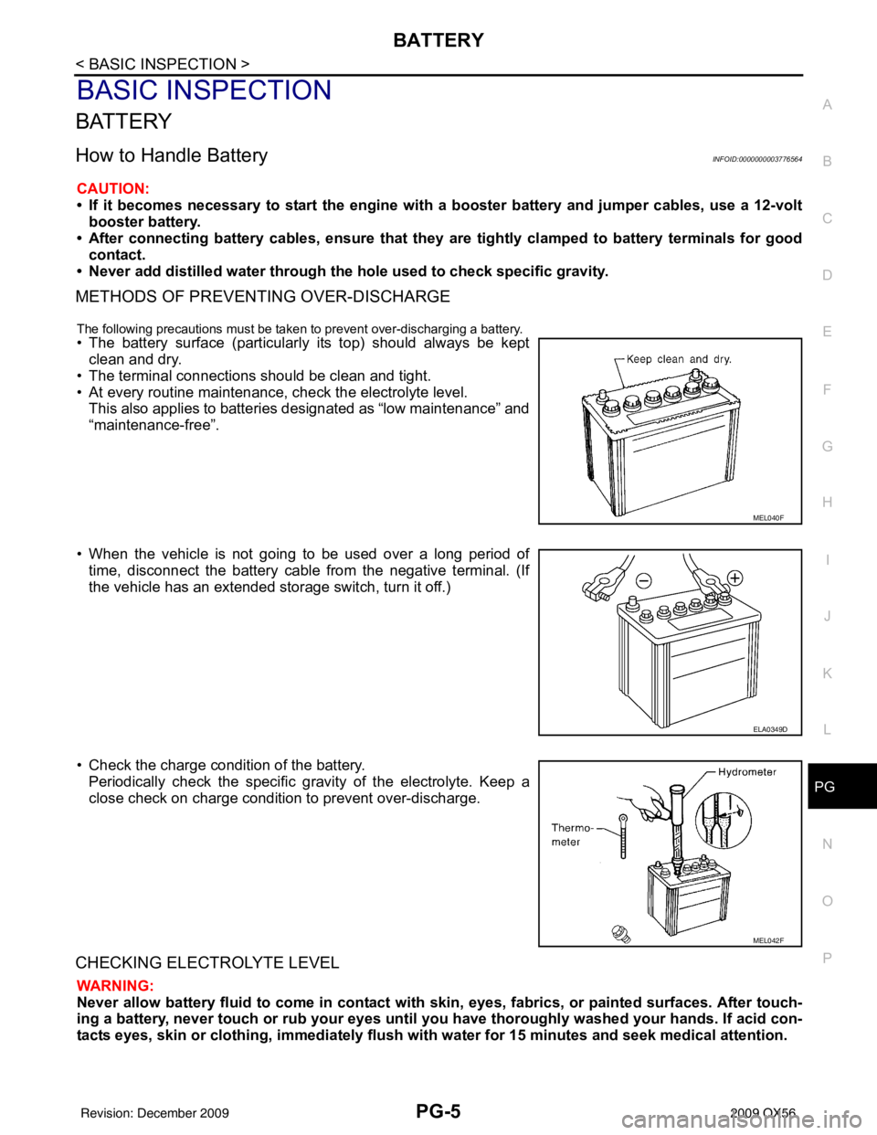
• The battery surface (particularly its top) should always be kept
clean and dry.
• The terminal connections should be clean and tight.
• At every routine maintenance, check the electrolyte level. This also applies to batteries designated as “low maintenance” and
“maintenance-free”.
• When the vehicle is not going to be used over a long period of time, disconnect the battery cable from the negative terminal. (If
the vehicle has an extended storage switch, turn it off.)
• Check the charge condition of the battery. Periodically check the specific gr avity of the electrolyte. Keep a
close check on charge condition to prevent over-discharge.
CHECKING ELECTROLYTE LEVEL
WARNING:
Never allow battery fluid to come in contact with skin, eyes, fabrics, or painted surfaces. After touch-
ing a battery, never touch or rub your eyes until you have thoroughly washed your hands. If acid con-
tacts eyes, skin or clothing, imme diately flush with water for 15 minutes and seek medical attention.
MEL040F
ELA0349D
MEL042F
Revision: December 20092009 QX56
Page 3120 of 4171
BCM (BODY CONTROL MODULE)RF-29
< ECU DIAGNOSIS >
C
DE
F
G H
I
J
L
M A
B
RF
N
O P
DTC Inspection Priority ChartINFOID:0000000005867492
If some DTCs are displayed at the same time, perform inspections one by one based on the following priority
chart.
DTC IndexINFOID:0000000005867493
NOTE: Details of time display
• CRNT: Displays when there is a malfunction now or after returning to the normal condition until turning igni-
tion switch OFF → ON again.
• 1 - 39: Displayed if any previous ma lfunction is present when current conditi on is normal. It increases like 1
→ 2 → 3...38 → 39 after returning to the normal condition whenever ignition switch OFF → ON. The counter
remains at 39 even if the number of cycles exceeds it. It is counted from 1 again when turning ignition switch
OFF → ON after returning to the normal condi tion if the malfunction is detected again.
Display contents of CONSULT Fail-safe Cancellation
U1000: CAN COMM CIRCUIT I nhibit engine crankingWhen the BCM re-establishes communication with the other mod-
ules.
U1010: CONTROL UNIT (CAN) Inhibit engine cranking When the BCM re-start communicating with the other modules.
Priority DTC
1 • U1000: CAN COMM CIRCUIT
• U1010: CONTROL UNIT (CAN)
2 • B2190: NATS ANTENNA AMP
• B2191: DIFFERENCE OF KEY
• B2192: ID DISCORD BCM-ECM
• B2193: CHAIN OF BCM-ECM
• B2013: STRG COMM 1
• B2552: INTELLIGENT KEY
• B2590: NATS MALFUNCTION
3 • C1729: VHCL SPEED SIG ERR
• C1735: IGNITION SIGNAL
4 • C1704: LOW PRESSURE FL
• C1705: LOW PRESSURE FR
• C1706: LOW PRESSURE RR
• C1707: LOW PRESSURE RL
• C1708: [NO DATA] FL
• C1709: [NO DATA] FR
• C1710: [NO DATA] RR
• C1711: [NO DATA] RL
• C1712: [CHECKSUM ERR] FL
• C1713: [CHECKSUM ERR] FR
• C1714: [CHECKSUM ERR] RR
• C1715: [CHECKSUM ERR] RL
• C1716: [PRESSDATA ERR] FL
• C1717: [PRESSDATA ERR] FR
• C1718: [PRESSDATA ERR] RR
• C1719: [PRESSDATA ERR] RL
• C1720: [CODE ERR] FL
• C1721: [CODE ERR] FR
• C1722: [CODE ERR] RR
• C1723: [CODE ERR] RL
• C1724: [BATT VOLT LOW] FL
• C1725: [BATT VOLT LOW] FR
• C1726: [BATT VOLT LOW] RR
• C1727: [BATT VOLT LOW] RL
Revision: December 20092009 QX56
Page 3134 of 4171
SQUEAK AND RATTLE TROUBLE DIAGNOSESRF-43
< SYMPTOM DIAGNOSIS >
C
DE
F
G H
I
J
L
M A
B
RF
N
O P
If the noise can be duplicated easily during the test drive, to help identify the source of the noise, try to dupli-
cate the noise with the vehicle stopped by doing one or all of the following:
1) Close a door.
2) Tap or push/pull around the area where the noise appears to be coming from.
3) Rev the engine.
4) Use a floor jack to recreate vehicle “twist”.
5) At idle, apply engine load. With brakes appllied, place A/T shift selector in drive position.
6) Raise the vehicle on a hoist and hit a tire with a rubber hammer.
• Drive the vehicle and attempt to duplicate the conditions the customer states exist when the noise occurs.
• If it is difficult to duplicate the noise, drive the vehicle slowly on an undulating or rough road to stress the
vehicle body.
CHECK RELATED SERVICE BULLETINS
After verifying the customer concern or symptom, check ASIST for Technical Service Bulletins (TSBs) related
to that concern or symptom.
If a TSB relates to the symptom, follow the procedure to repair the noise.
LOCATE THE NOISE AND IDENTIFY THE ROOT CAUSE
1. Narrow down the noise to a general area. To help pinpoint the source of the noise, use a listening tool (Chassis Ear: J-39570, Engine Ear and mechanics stethoscope).
2. Narrow down the noise to a more specific area and identify the cause of the noise by:
• removing the components in the area that you suspect the noise is coming from. Do not use too much force when removing clips and fasteners, otherwise clips and fastener can be broken
or lost during the repair, resulting in the creation of new noise.
• tapping or pushing/pulling the component that you suspect is causing the noise.
Do not tap or push/pull the component with excessive force, otherwise the noise will be eliminated only tem-
porarily.
• feeling for a vibration with your hand by touching the component(s) that you suspect is (are) causing the
noise.
• placing a piece of paper between components that you suspect are causing the noise.
• looking for loose components and contact marks. Refer to RF-44, "
Generic Squeak and Rattle Troubleshooting".
REPAIR THE CAUSE
• If the cause is a loose component, tighten the component securely.
• If the cause is insufficient clearance between components:
- separate components by repositioning or loos ening and retightening the component, if possible.
- insulate components with a suitable insulator such as urethane pads, foam blocks, felt cloth tape or urethane tape. A Nissan Squeak and Rattle Kit (J-43980) is av ailable through your authorized Nissan Parts Depart-
ment.
CAUTION:
Do not use excessive force as many components are constructed of plastic and may be damaged.
NOTE:
Always check with the Parts Department for the latest parts information.
The following materials are contained in the Niss an Squeak and Rattle Kit (J-43980). Each item can be
ordered separately as needed.
URETHANE PADS [1.5 mm (0.059 in) thick]
Insulates connectors, harness, etc.
76268-9E005: 100 ×135 mm (3.94 ×5.31 in)/76884-71L01: 60 ×85 mm (2.36 ×3.35 in)/76884-
71L02: 15 ×25 mm (0.59 ×0.98 in)
INSULATOR (Foam blocks)
Insulates components from contact. Can be used to fill space behind a panel.
73982-9E000: 45 mm (1.77 in) thick, 50 ×50 mm (1.97 ×1.97 in)/73982-
50Y00: 10 mm (0.39 in) thick, 50 ×50 mm (1.97 ×1.97 in)
INSULATOR (Light foam block)
80845-71L00: 30 mm (1.18 in) thick, 30 ×50 mm (1.18 ×1.97 in)
FELT CLOTHTAPE
Used to insulate where movement does not occur. Ideal for instrument panel applications.
68370-4B000: 15 ×25 mm (0.59 ×0.98 in) pad/68239-13E00: 5 mm (0.20 in) wide tape roll
The following materials, not found in the kit, can also be used to repair squeaks and rattles.
UHMW (TEFLON) TAPE
Revision: December 20092009 QX56
Page 3162 of 4171
RSU-14
< REMOVAL AND INSTALLATION >
REAR SUSPENSION MEMBER
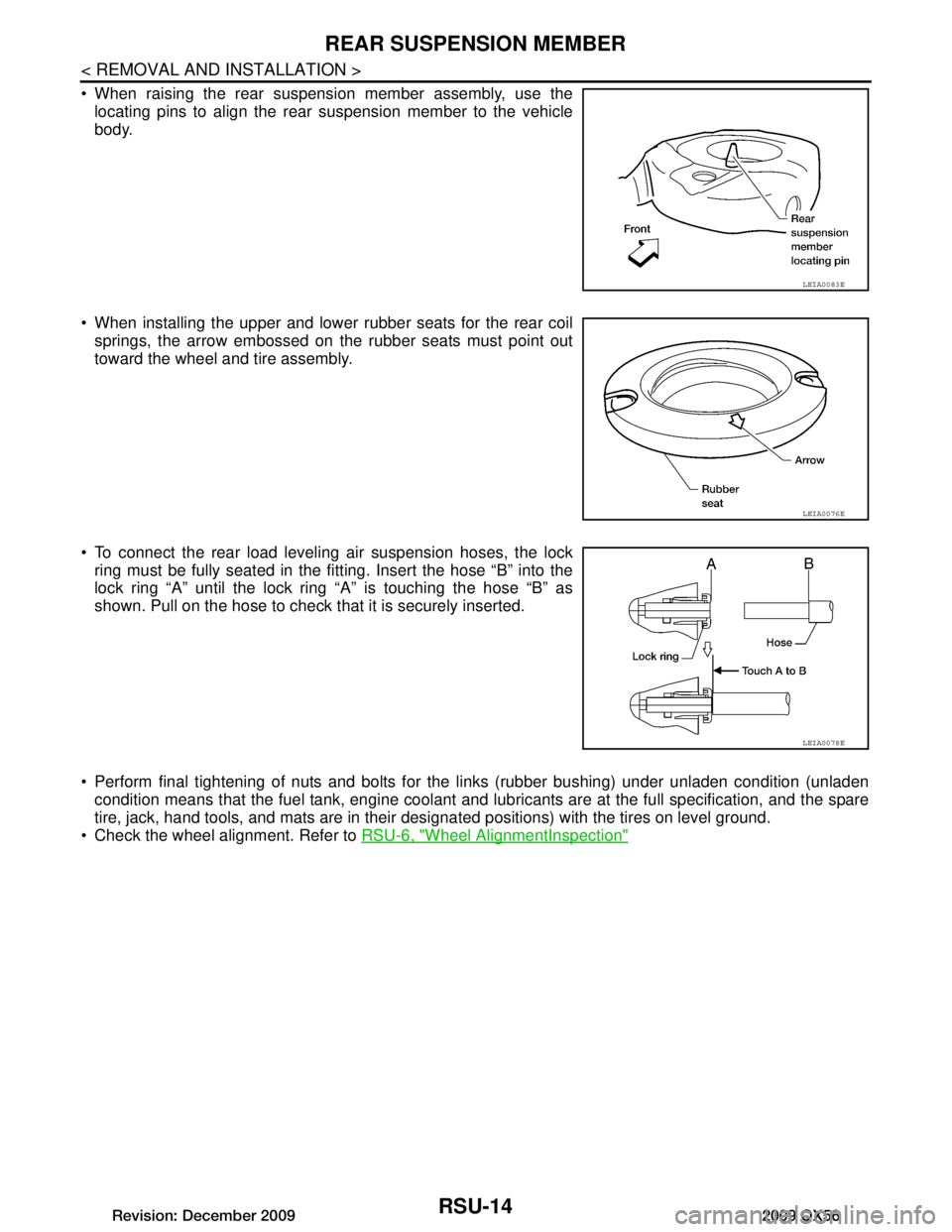
When raising the rear suspension member assembly, use thelocating pins to align the rear suspension member to the vehicle
body.
When installing the upper and lower rubber seats for the rear coil springs, the arrow embossed on the rubber seats must point out
toward the wheel and tire assembly.
To connect the rear load leveling air suspension hoses, the lock ring must be fully seated in the fitt ing. Insert the hose “B” into the
lock ring “A” until the lock ring “A” is touching the hose “B” as
shown. Pull on the hose to check that it is securely inserted.
Perform final tightening of nuts and bolts for the links (rubber bushing) under unladen condition (unladen condition means that the fuel tank, engine coolant and l ubricants are at the full specification, and the spare
tire, jack, hand tools, and mats are in their designated positions) with the tires on level ground.
Check the wheel alignment. Refer to RSU-6, "Wheel AlignmentInspection"
LEIA0083E
LEIA0076E
LEIA0078E
Revision: December 20092009 QX56
Page 3166 of 4171

RSU-18
< REMOVAL AND INSTALLATION >
SUSPENSION ARM
17. Remove the two bolts to disconnect the seat belt latch anchorfrom the rear suspension member.
18. Disconnect both of the connecting rods from the front lower link.
19. Set a suitable jack under the rear suspension member.
20. Remove the six rear suspension member bolts.
21. Slowly lower the jack to remove the rear suspension member assembly.
22. Remove suspension arm from rear suspension member.
INSPECTION AFTER REMOVAL
Check suspension arm for damage, cracks, deformation and replace if necessary.
Check rubber bushing for damage, cracks and deformation. Replace suspension arm assembly if neces- sary.
Before checking, turn ball joint at least 10 revolutions so that ball joint is properly broken in.
Check ball joint. Replace suspension arm assembly if any of the following exists:
- Ball stud is worn.
- Joint is hard to swing.
- Play in axial direction is excessive.
INSTALLATION
Installation is in the reverse order of removal.
Tighten the nuts and bolts to specification. Refer to RSU-11, "Removal and Installation"
.
Perform final tightening of nuts and bolts for the links (rubber bushing) under unladen condition (unladen
condition means that the fuel tank, engine coolant and l ubricants are at the full specification, and the spare
tire, jack, hand tools, and mats are in their designated positions) with the tires on level ground.
Check the wheel alignment. Refer to RSU-29, "Wheel Alignment (Unladen
*1)".
LEIA0075E
Swinging force (A) : Refer to RSU-29, "Ball Joint"
Turning force (B) : Refer to RSU-29, "Ball Joint"
Vertical end play (C) : Refer to RSU-29, "Ball Joint"
SFA858A
Revision: December 20092009 QX56
Page 3168 of 4171
RSU-20
< REMOVAL AND INSTALLATION >
FRONT LOWER LINK
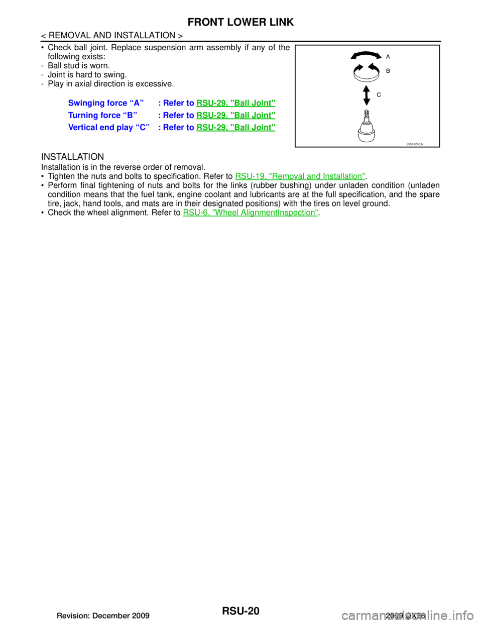
Check ball joint. Replace suspension arm assembly if any of thefollowing exists:
- Ball stud is worn.
- Joint is hard to swing.
- Play in axial direction is excessive.
INSTALLATION
Installation is in the reverse order of removal.
Tighten the nuts and bolts to specification. Refer to RSU-19, "Removal and Installation"
.
Perform final tightening of nuts and bolts for the links (rubber bushing) under unladen condition (unladen condition means that the fuel tank, engine coolant and l ubricants are at the full specification, and the spare
tire, jack, hand tools, and mats are in their designated positions) with the tires on level ground.
Check the wheel alignment. Refer to RSU-6, "Wheel AlignmentInspection"
.
Swinging force “A” : Refer to
RSU-29, "Ball Joint"
Turning force “B” : Refer to RSU-29, "Ball Joint"
Vertical end play “C” : Refer to RSU-29, "Ball Joint"
SFA858A
Revision: December 20092009 QX56
Page 3176 of 4171
RSU-28
< REMOVAL AND INSTALLATION >
HEIGHT SENSOR
1. Start the engine.
2. Use CONSULT-III to perform "STANDARD HEIGHT LEVEL" work support function.
3. Using data monitor of CONSULT-III, verify "HEIGT CALC" is at 0 mm.
4. Check the vehicle height. Refer to RSU-30, "Wheelarch Height (Unladen*
1)" . If vehicle height is not
within ± 10 mm (0 ± 0.39 in) of the specification, perform the initialization procedure. Refer to RSU-26,
"Initialization Procedure".
Revision: December 20092009 QX56