Page 3844 of 4171
TM-196
< ON-VEHICLE REPAIR >
SHIFT CONTROL SYSTEM
ON-VEHICLE REPAIR
SHIFT CONTROL SYSTEM
A/T Shift Selector Removal and InstallationINFOID:0000000004187479
REMOVAL
1. Remove A/T finisher. Refer to IP-19, "Removal and Installation".
2. Disconnect A/T shift selector control cable.
3. Disconnect A/T shift selector harness connector.
4. Remove A/T shift selector assembly.
INSTALLATION
Installation is in reverse order of removal. Be careful of the following:
After installation is completed, adjust and check A/T position. Refer to TM-195, "Adjustment of A/T Position"
,
TM-195, "Checking of A/T Position"
.
1. Select lever handle 2. A/T console finisher 3. A/T shift selector
4. Position lamp 5. A/T shift selector control cable 6. Lock plate
LCIA0348E
Revision: December 20092009 QX56
Page 3845 of 4171
AIR BREATHER HOSETM-197
< ON-VEHICLE REPAIR >
CEF
G H
I
J
K L
M A
B
TM
N
O P
AIR BREATHER HOSE
2WD
2WD : Removal and InstallationINFOID:0000000005892370
CAUTION:
Install air breather hose with paint mark at upper side.
When installing the air breather hose, do not crush or block by folding or bending the hose.
When inserting the hose to the tran smission tube, be sure to insert it fully until its end reaches the
tube bend portion.
Make sure clip is securely installed to bracket.
4WD
4WD : Removal and InstallationINFOID:0000000005892369
REMOVAL
A. Set air breather hose with
paint mark at upper side B. Clip (set securely to bracket)
AWDIA0554GB
Revision: December 20092009 QX56
Page 3846 of 4171
TM-198
< ON-VEHICLE REPAIR >
AIR BREATHER HOSE
INSTALLATION
CAUTION:
Make sure there are no pinched or restricted areas on each air breather hose caused by folding or
bending when installing it.
1. Install each air breather hose into the breather tube (4). Set
each air breather hose with paint mark facing upward.
A/T breather hose (1)
Transfer breather hose (2)
Actuator/transfer motor breather hose (3)
Paint marks (A)
2. Install actuator/transfer motor air breather hose (1) and transfer air breather hose (2) on clip (A) with the paint mark (B) facing
upward.
:Front
1. Breather tube 2. Clip A 3. Clip B
4. Clip C 5. Clip D 6. Actuator
7. Air breather hose clamp 8. Clip E 9. Transfer motor
10. Breather tube (transfer) Vehicle front
AWDIA0010ZZ
ALDIA0110ZZ
ALDIA0111ZZ
Revision: December 20092009 QX56
Page 3847 of 4171

AIR BREATHER HOSETM-199
< ON-VEHICLE REPAIR >
CEF
G H
I
J
K L
M A
B
TM
N
O P
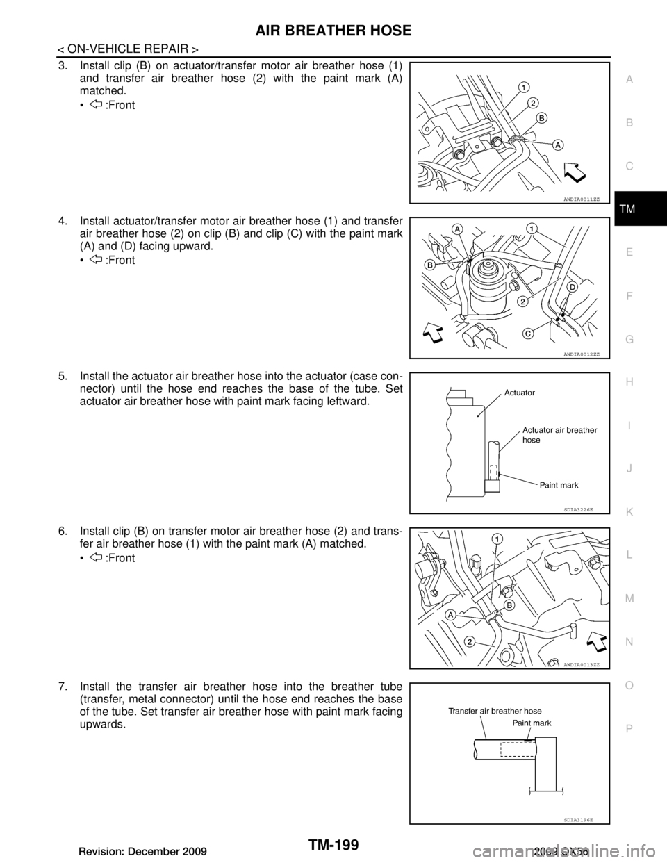
3. Install clip (B) on actuator/transfer motor air breather hose (1) and transfer air breather hose (2) with the paint mark (A)
matched.
:Front
4. Install actuator/transfer motor air breather hose (1) and transfer air breather hose (2) on clip (B) and clip (C) with the paint mark
(A) and (D) facing upward.
:Front
5. Install the actuator air breather hose into the actuator (case con-
nector) until the hose end reaches the base of the tube. Set
actuator air breather hose with paint mark facing leftward.
6. Install clip (B) on transfer motor air breather hose (2) and trans- fer air breather hose (1) with the paint mark (A) matched.
:Front
7. Install the transfer air breather hose into the breather tube (transfer, metal connector) until the hose end reaches the base
of the tube. Set transfer air breather hose with paint mark facing
upwards.
AWDIA0011ZZ
AWDIA0012ZZ
SDIA3226E
AWDIA0013ZZ
SDIA3196E
Revision: December 20092009 QX56
Page 3848 of 4171
TM-200
< ON-VEHICLE REPAIR >
AIR BREATHER HOSE
8. Install the transfer motor air breather hose into the transfermotor (case connector) until the hose end reaches the end of
the curved section. Set transfer motor air breather hose with
paint mark facing leftward.
SDIA3194E
Revision: December 20092009 QX56
Page 3849 of 4171

OIL PANTM-201
< ON-VEHICLE REPAIR >
CEF
G H
I
J
K L
M A
B
TM
N
O P
OIL PAN
Oil PanINFOID:0000000005880214
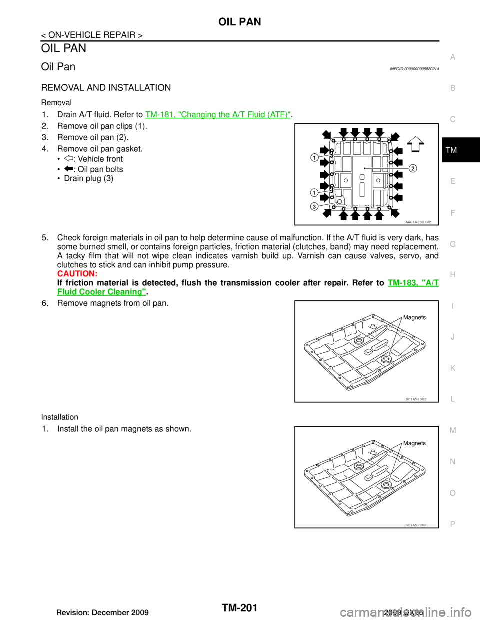
REMOVAL AND INSTALLATION
Removal
1. Drain A/T fluid. Refer to TM-181, "Changing the A/T Fluid (ATF)".
2. Remove oil pan clips (1).
3. Remove oil pan (2).
4. Remove oil pan gasket. : Vehicle front
: Oil pan bolts
Drain plug (3)
5. Check foreign materials in oil pan to help determine c ause of malfunction. If the A/T fluid is very dark, has
some burned smell, or contains foreign particles, friction material (clutches, band) may need replacement.
A tacky film that will not wipe clean indicates varnis h build up. Varnish can cause valves, servo, and
clutches to stick and can inhibit pump pressure.
CAUTION:
If friction material is detected, flush th e transmission cooler after repair. Refer to TM-183, "A/T
Fluid Cooler Cleaning".
6. Remove magnets from oil pan.
Installation
1. Install the oil pan magnets as shown.
AWDIA0023ZZ
SCIA5200E
SCIA5200E
Revision: December 20092009 QX56
Page 3850 of 4171

TM-202
< ON-VEHICLE REPAIR >
OIL PAN
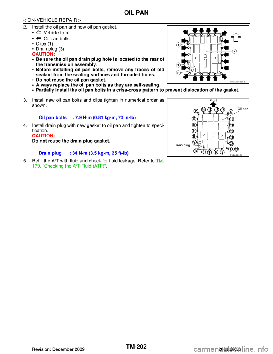
2. Install the oil pan and new oil pan gasket. : Vehicle front
: Oil pan bolts
Clips (1)
Drain plug (3)
CAUTION:
Be sure the oil pan drain plug hole is located to the rear ofthe transmission assembly.
Before installing oil pan bolts, remove any traces of old sealant from the sealing su rfaces and threaded holes.
Do not reuse the oil pan gasket.
Always replace the oil pan bolts as they are self-sealing.
Partially install the oil pan bolts in a criss- cross pattern to prevent dislocation of the gasket.
3. Install new oil pan bolts and clips tighten in numerical order as shown.
4. Install drain plug with new gasket to oil pan and tighten to speci- fication.
CAUTION:
Do not reuse the drain plug gasket.
5. Refill the A/T with fluid and check for fluid leakage. Refer to TM-
179, "Checking the A/T Fluid (ATF)".
AWDIA0023ZZ
Oil pan bolts : 7.9 N·m (0.81 kg-m, 70 in-lb)
Drain plug : 34 N·m (3.5 kg-m, 25 ft-lb)
SCIA4113E
Revision: December 20092009 QX56
Page 3851 of 4171
CONTROL VALVE WITH TCMTM-203
< ON-VEHICLE REPAIR >
CEF
G H
I
J
K L
M A
B
TM
N
O P
CONTROL VALVE WITH TCM
Control Valve with TCM and A/T Fluid Temperature Sensor 2INFOID:0000000004219688
COMPONENTS
CONTROL VALVE WITH TCM REMOVAL AND INSTALLATION
Removal
1. Disconnect negative battery terminal. Refer to PG-77, "Removal and Installation".
2. Drain A/T fluid. Refer to TM-181, "Changing the A/T Fluid (ATF)"
.
3. Disconnect A/T assembly harness connector.
1. Transmission 2. Snap ring 3. Sub-harness
4. Control valve with TCM 5. Bracket 6. A/T fluid temperature sensor 2
7. Oil pan gasket 8. Brackets 9. Oil pan bolt
10. Oil pan 11. Magnet 12. Drain plug
13. Drain plug gasket 14. A/T assembly harness connector 15. O-ring
AWDIA0024ZZ
Revision: December 20092009 QX56