Page 4081 of 4171
PREPARATIONWT-39
< PREPARATION >
C
DF
G H
I
J
K L
M A
B
WT
N
O P
PREPARATION
PREPARATION
Special Service ToolINFOID:0000000003772400
The actual shapes of Kent-Moore tools may differ from those of special service tools illustrated here.
Commercial Service ToolINFOID:0000000003772401
Tool number
(Kent-Moore No.)
Tool name Description
KV991B1000
(J-45295)
Transmitter activation tool • Transmitter wake up operation
• ID registration procedure
WEIA0144E
Tool name
Description
Power tool Removing wheel nuts
PBIC0190E
Revision: December 20092009 QX56
Page 4082 of 4171
WT-40
< ON-VEHICLE MAINTENANCE >
WHEEL
ON-VEHICLE MAINTENANCE
WHEEL
InspectionINFOID:0000000003772402
1. Check tires for wear and improper inflation.
2. Check wheels for deformation, cracks and other damage. Ifdeformed, remove wheel and check wheel runout.
a. Remove tire from wheel and mount wheel on a tire balance machine.
b. Set dial indicator as shown. Refer to WT-45, "
Road Wheel" .
3. Check front wheel bearings for looseness.
4. Check front suspension for looseness.
SFA975B
Revision: December 20092009 QX56
Page 4083 of 4171

WHEEL AND TIRE ASSEMBLYWT-41
< ON-VEHICLE REPAIR >
C
DF
G H
I
J
K L
M A
B
WT
N
O P
ON-VEHICLE REPAIR
WHEEL AND TIRE ASSEMBLY
AdjustmentINFOID:0000000005873223
BALANCING WHEELS (ADH ESIVE WEIGHT TYPE)
Preparation Before Adjustment
Remove inner and outer balance weights from the r oad wheel using releasing agent, remove double-faced
adhesive tape from the road wheel.
CAUTION:
• Be careful not scratch the road wheel during removal.
• After removing double-faced adhesive tape, wipe clean traces of releasing agent from the road
wheel.
Wheel Balance Adjustment
CAUTION:
• Use canter hole cone-type clampi ng machines due to clad wheels.
• If a balancer machine has an adhesive weight mode setting, select the adhesive weight mode setting and
skip Step 2. below. If a balancer machine only has the clip-on (rim flange) weight mode setting, follow Step 2.
to calculate the correct size adhesive weight.
1. Set road wheel on balancer machine using the cent er hole as a guide. Start the balancer machine.
2. For tire balance machines that only have a clip-on (ri m flange) weight mode setting, follow this step to cal-
culate the correct size adhesive weight to use. When inner and outer imbalance values are shown on the
balancer machine indicator, multiply outer imbalance value by 5/3 (1.67) to determine balance weight that
should be used. Select the outer balance weight with a value closest to the calculated value above and
install in to the designated outer position of, or at the designated angle in relation to the road wheel.
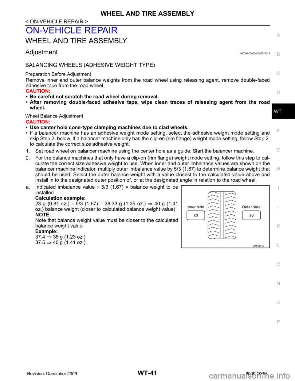
a. Indicated imbalance value × 5/3 (1.67) = balance weight to be
installed
Calculation example:
23 g (0.81 oz.) × 5/3 (1.67) = 38.33 g (1.35 oz.) ⇒ 40 g (1.41
oz.) balance weight (closer to calculated balance weight value)
NOTE:
Note that balance weight value must be closer to the calculated
balance weight value.
Example:
37.4 ⇒ 35 g (1.23 oz.)
37.5 ⇒ 40 g (1.41 oz.)
SMA054D
Revision: December 20092009 QX56
Page 4084 of 4171

WT-42
< ON-VEHICLE REPAIR >
WHEEL AND TIRE ASSEMBLY
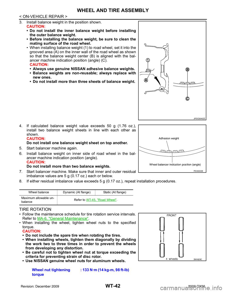
3. Install balance weight in the position shown.CAUTION:
• Do not install the inner bala nce weight before installing
the outer balance weight.
• Before installing the balance weight, be sure to clean the mating surface of the road wheel.
• When installing balance weight (1) to road wheel, set it into the grooved area (A) on the inner wall of the road wheel as shown
so that the balance weight center (B) is aligned with the bal-
ancer machine indication position (angle) (C).
CAUTION:
• Always use genuine NISSAN adhesive balance weights.
• Balance weights are non-reusable; always replace withnew ones.
• Do not install more than three sheets of balance weight.
4. If calculated balance weight value exceeds 50 g (1.76 oz.), install two balance weight sheets in line with each other as
shown.
CAUTION:
Do not install one balance weight sheet on top another.
5. Start balancer machine again.
6. Install balance weight on inner side of road wheel in the bal- ancer machine indication position (angle).
CAUTION:
Do not install more than two balance weights.
7. Start balancer machine. Make sure that inner and outer residual imbalance values are 5 g (0.17 oz.) each or below.
8. If either residual imbalance value exceeds 5 g (0.17 oz.), repeat installation procedures.
TIRE ROTATION
• Follow the maintenance schedule for tire rotation service intervals.
Refer to MA-6, "
General Maintenance".
• When installing the wheel, tighten wheel nuts to the specified
torque.
CAUTION:
• Do not include the spare tire when rotating the tires.
• When installing wheels, tighten them diagonally by dividing
the work two to three times in order to prevent the wheels
from developing any distortion.
• Be careful not to tighten wheel nut at torque exceeding the criteria for preventing strain of disc rotor.
• Use NISSAN genuine wheel nuts for aluminum wheels.
JPEIC0040ZZ
Wheel balance Dynamic (At flange) Static (At flange)
Maximum allowable un-
balance Refer to
WT-45, "
Road Wheel".
PEIA0033E
Wheel nut tightening
torque : 133 N·m (14 kg-m, 98 ft-lb)
SMA829C
Revision: December 20092009 QX56
Page 4085 of 4171

REMOVAL AND INSTALLATIONWT-43
< REMOVAL AND INSTALLATION >
C
DF
G H
I
J
K L
M A
B
WT
N
O P
REMOVAL AND INSTALLATION
REMOVAL AND INSTALLATION
Transmitter (Pressure Sensor)INFOID:0000000003772405
REMOVAL
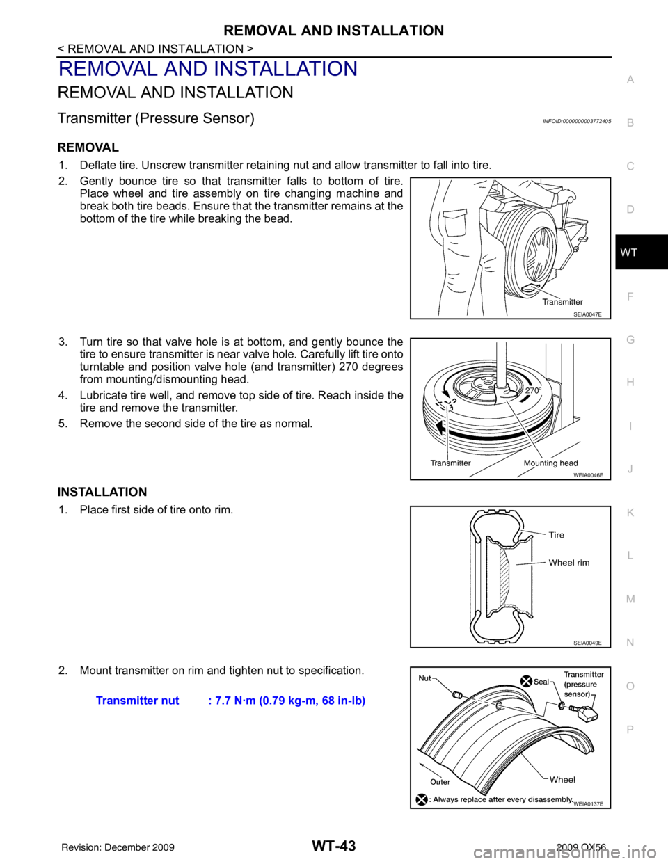
1. Deflate tire. Unscrew transmitter retaining nut and allow transmitter to fall into tire.
2. Gently bounce tire so that transmitter falls to bottom of tire. Place wheel and tire assembly on tire changing machine and
break both tire beads. Ensure that the transmitter remains at the
bottom of the tire while breaking the bead.
3. Turn tire so that valve hole is at bottom, and gently bounce the tire to ensure transmitter is near valve hole. Carefully lift tire onto
turntable and position valve hole (and transmitter) 270 degrees
from mounting/dismounting head.
4. Lubricate tire well, and remove top side of tire. Reach inside the tire and remove the transmitter.
5. Remove the second side of the tire as normal.
INSTALLATION
1. Place first side of tire onto rim.
2. Mount transmitter on rim and tighten nut to specification.
SEIA0047E
WEIA0046E
SEIA0049E
Transmitter nut : 7.7 N·m (0.79 kg-m, 68 in-lb)
WEIA0137E
Revision: December 20092009 QX56
Page 4086 of 4171
WT-44
< REMOVAL AND INSTALLATION >
REMOVAL AND INSTALLATION
3. Place wheel on turntable of tire machine. Ensure that transmitteris 270 degrees from mounting/dismounting head.
NOTE:
Do not touch transmitter with mounting head.
4. Lubricate tire well, and install second side of tire as normal. Ensure that tire does not rotate relative to rim.
5. Inflate tire and balance the wheel and tire assembly. Refer to WT-41, "
Adjustment".
6. Install Wheel and tire assembly in appropriate wheel position on vehicle.
NOTE:
If replacing the transmitter, then transmitter wake up operation
must be performed. Refer to WT-5, "
Transmitter Wake Up Operation" .
7. Adjust neutral position of steering angle sensor. Refer to BRC-8, "
ADJUSTMENT OF STEERING ANGLE
SENSOR NEUTRAL POSITION : Special Repair Requirement" .
WEIA0046E
Revision: December 20092009 QX56
Page 4087 of 4171
SERVICE DATA AND SPECIFICATIONS (SDS)WT-45
< SERVICE DATA AND SPECIFICATIONS (SDS)
C
DF
G H
I
J
K L
M A
B
WT
N
O P
SERVICE DATA AND SPECIFICATIONS (SDS)
SERVICE DATA AND SPECIFICATIONS (SDS)
Road WheelINFOID:0000000004201424
TireINFOID:0000000003772407
Unit: kPa (kg/cm2, psi)
Wheel type AluminumSte el
Inside Outside
Maximum radial
runout limit Lateral mm (in)
0.3 (0.012) or less 1.0 (0.039) or less 0.9 (0.035) or less
Radial mm (in) 0.3 (0.012) or less 0.8 (0.031) or less 0.4 (0.016) or less
Maximum residual im-
balance Dynamic (at rim flange)
Less than 5 g (0.18 oz) (per side)
Static (at rim flange) Less than 10 g (0.35 oz)
Tire size Air pressure
Conventional tire Spare tire
Full size spare tire —240 (2.4, 35)
P275/60R20 240 (2.4, 35)—
Revision: December 20092009 QX56
Page 4089 of 4171

WW-2
Wiring Diagram .......................................................61
Fail Safe .................................................................64
SYMPTOM DIAGNOSIS .............................66
WIPER AND WASHER SYSTEM SYMPTOMS
...
66
Symptom Table ................................................... ...66
NORMAL OPERATING CONDITION ................69
Description ........................................................... ...69
FRONT WIPER DOES NOT OPERATE ............70
Description ........................................................... ...70
Diagnosis Procedure ..............................................70
PRECAUTION .............................................72
PRECAUTION ... .............................................. ...72
Precaution for Supplemental Restraint System
(SRS) "AIR BAG" and "SEAT BELT PRE-TEN-
SIONER" .............................................................. ...
72
Precaution Necessary for Steering Wheel Rota-
tion After Battery Disconnect ..................................
72
ON-VEHICLE REPAIR ................................74
FRONT WIPER ARM ...................................... ...74
Front Wiper Arms ................................................ ...74
FRONT WIPER DRIVE ASSEMBLY .................75
Wiper Motor and Linkage ..................................... ...75
FRONT WASHER TUBE ...................................76
Washer Tube Layout ............................................ ...76
FRONT WASHER NOZZLE ..............................77
Washer Nozzle Adjustment .................................. ...77
WASHER TANK ................................................78
Washer Fluid Reservoir ..........................................78
FRONT WASHER PUMP ..................................79
Washer Motor ...................................................... ...79
FRONT WIPER AND WASHER SWITCH .........80
Wiper and Washer Switch .................................... ...80
REAR WIPER AND WASHER SYSTEM ...........81
Rear Wiper Arm ................................................... ...81
Rear Wiper Motor ....................................................81
Rear Washer Nozzle Adjustment ............................82
Rear Washer Tube Layout ......................................83
Rear Washer Nozzle ...............................................83
Rear Wiper and Washer Switch ..............................83
Washer Fluid Reservoir ....................................... ...84
Washer Motor .........................................................84
Revision: December 20092009 QX56