2009 INFINITI QX56 key
[x] Cancel search: keyPage 1787 of 4171
![INFINITI QX56 2009 Factory Service Manual
EC-460
< ECU DIAGNOSIS >[VK56DE]
ECM
*1: 1st trip DTC No. is
the same as DTC No.
*2: This number is prescribed by SAE J2012.
*3: In Diagnostic Test Mode II (Self-diagnostic results), this number i INFINITI QX56 2009 Factory Service Manual
EC-460
< ECU DIAGNOSIS >[VK56DE]
ECM
*1: 1st trip DTC No. is
the same as DTC No.
*2: This number is prescribed by SAE J2012.
*3: In Diagnostic Test Mode II (Self-diagnostic results), this number i](/manual-img/42/57031/w960_57031-1786.png)
EC-460
< ECU DIAGNOSIS >[VK56DE]
ECM
*1: 1st trip DTC No. is
the same as DTC No.
*2: This number is prescribed by SAE J2012.
*3: In Diagnostic Test Mode II (Self-diagnostic results), this number is controlled by NISSAN.
*4: SRT code will not be set if the self-diagnostic result is NG.
*5: The troubleshooting for this DTC needs CONSULT-III.
*6: When the fail-safe operations for both self-diagnoses occur, the MIL illuminates.
*7: When the ECM is in the mode of displaying SRT status, MIL may flash. For the details, refer to "How to Display SRT Status".
*8: 2WD models
*9: Models with ICC
*10: Models without ICC
Emission-related Diagnostic InformationINFOID:0000000004114214
DTC AND 1ST TRIP DTC
The 1st trip DTC (whose number is the same as the DT C number) is displayed for the latest self-diagnostic
result obtained. If the ECM memory was cleared previous ly, and the 1st trip DTC did not reoccur, the 1st trip
DTC will not be displayed.
If a malfunction is detected during the 1st trip, the 1st trip DTC is stored in the ECM memory. The MIL will not
light up (two trip detection logic). If the same malfunc tion is not detected in the 2nd trip (meeting the required
driving pattern), the 1st trip DTC is cleared from the ECM memory. If the same malfunction is detected in the
2nd trip, both the 1st trip DTC and DTC are stored in t he ECM memory and the MIL lights up. In other words,
the DTC is stored in the ECM memory and the MIL light s up when the same malfunction occurs in two consec-
utive trips. If a 1st trip DTC is stored and a non-diagnostic operation is performed between the 1st and 2nd
trips, only the 1st trip DTC will continue to be stored. Fo r malfunctions that blink or light up the MIL during the
1st trip, the DTC and 1st trip DTC are stored in the ECM memory.
DIFFERENCE OF KEY P1615 1615 — 2 — SEC-30
INTERLOCK P1730 1730 — 1×TM-76
INPUT CLUTCH SOL P1752 1752 — 1 ×TM-80
FR BRAKE SOLENOID P1757 1757 — 1 ×TM-82
DRCT CLUTCH SOL P1762 1762 — 1 ×TM-84
HLR CLUTCH SOLENOID P1767 1767 — 1 ×TM-86
L C BRAKE SOLENOID P1772 1772 — 1 ×TM-88
L C BRAKE SOLENOID P1774 1774 — 1 ×TM-90
BRAKE SW/CIRCUIT P1805 1805 — 2 — EC-348
ETC MOT PWR-B1 P2100 2100 — 1×EC-351
ETC FUNCTION/CIRC-B1 P2101 2101 — 1 ×EC-354
ETC MOT PWR P2103 2103 — 1 ×EC-351
ETC MOT-B1 P2118 2118 — 1 ×EC-358
ETC ACTR-B1 P2119 2119 — 1 ×EC-360
APP SEN 1/CIRC P2122 2122 — 1 ×EC-362
APP SEN 1/CIRC P2123 2123 — 1 ×EC-362
APP SEN 2/CIRC P2127 2127 — 1 ×EC-365
APP SEN 2/CIRC P2128 2128 — 1 ×EC-365
TP SENSOR-B1 P2135 2135 — 1 ×EC-369
APP SENSOR P2138 2138 — 1 ×EC-373
A/F SENSOR1 (B1) P2A00 2A00 — 2 ×EC-377
A/F SENSOR1 (B2) P2A03 2A03 — 2 ×EC-377
Items
(CONSULT-IIl screen terms) DTC*
1
SRT code Trip MIL
Reference
page
CONSULT-IIl
GST*
2ECM*3
Revision: December 20092009 QX56
Page 1826 of 4171
PRECAUTIONSEM-3
< PRECAUTION >
C
DE
F
G H
I
J
K L
M A
EM
NP
O
PRECAUTION
PRECAUTIONS
Precaution for Supplemental
Restraint System (SRS) "AIR BAG" and "SEAT BELT
PRE-TENSIONER"
INFOID:0000000005885848
The Supplemental Restraint System such as “AIR BAG” and “SEAT BELT PRE-TENSIONER”, used along
with a front seat belt, helps to reduce the risk or severi ty of injury to the driver and front passenger for certain
types of collision. This system includes seat belt switch inputs and dual stage front air bag modules. The SRS
system uses the seat belt switches to determine the front air bag deployment, and may only deploy one front
air bag, depending on the severity of a collision and w hether the front occupants are belted or unbelted.
Information necessary to service the system safely is included in the SR and SB section of this Service Man-
ual.
WARNING:
• To avoid rendering the SRS inoper ative, which could increase the risk of personal injury or death in
the event of a collision which would result in air bag inflation, all maintenance must be performed by
an authorized NISSAN/INFINITI dealer.
• Improper maintenance, including in correct removal and installation of the SRS, can lead to personal
injury caused by unintentional act ivation of the system. For removal of Spiral Cable and Air Bag
Module, see the SR section.
• Do not use electrical test equipm ent on any circuit related to the SRS unless instructed to in this
Service Manual. SRS wiring harnesses can be identi fied by yellow and/or orange harnesses or har-
ness connectors.
PRECAUTIONS WHEN USING POWER TOOLS (AIR OR ELECTRIC) AND HAMMERS
WARNING:
• When working near the Airbag Diagnosis Sensor Un it or other Airbag System sensors with the Igni-
tion ON or engine running, DO NOT use air or el ectric power tools or strike near the sensor(s) with a
hammer. Heavy vibration could activate the sensor( s) and deploy the air bag(s), possibly causing
serious injury.
• When using air or electric power tools or hammers, always switch the Ignition OFF, disconnect the battery, and wait at least 3 minutes before performing any service.
Precaution Necessary for Steering Wheel Rotation After Battery Disconnect
INFOID:0000000005885849
NOTE:
• This Procedure is applied only to models with Intelligent Key system and NATS (NISSAN ANTI-THEFT SYS-
TEM).
• Remove and install all control units after disconnecti ng both battery cables with the ignition knob in the
″ LOCK ″ position.
• Always use CONSULT-III to perform self-diagnosis as a part of each function inspection after finishing work.
If DTC is detected, perform trouble diagnosis according to self-diagnostic results.
For models equipped with the Intelligent Key system and NATS , an electrically controlled steering lock mech-
anism is adopted on the key cylinder.
For this reason, if the battery is disconnected or if the battery is discharged, the steering wheel will lock and
steering wheel rotation will become impossible.
If steering wheel rotation is required when battery power is interrupted, follow the procedure below before
starting the repair operation.
OPERATION PROCEDURE
1. Connect both battery cables. NOTE:
Supply power using jumper cables if battery is discharged.
2. Use the Intelligent Key or mechanical key to turn the ignition switch to the ″ACC ″ position. At this time, the
steering lock will be released.
3. Disconnect both battery cables. The steering lock will remain released and the steering wheel can be
rotated.
4. Perform the necessary repair operation.
Revision: December 20092009 QX56
Page 1871 of 4171
EM-48
< ON-VEHICLE REPAIR >
TIMING CHAIN
Check for cracks and any excessive wear at link plates. Replace
chain if necessary.
• In the same way as for the LH bank, inspect the timing chain andassociated parts on the RH bank.
INSTALLATION
NOTE:
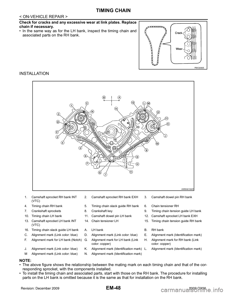
• The above figure shows the relationship between the ma ting mark on each timing chain and that of the cor-
responding sprocket, with the components installed.
• To install the timing chain and associated parts, start with those on the RH bank. The procedure for installing parts on the LH bank is omitted because it is t he same as that for installation on the RH bank.
PBIC0282E
1. Camshaft sprocket RH bank INT
(VTC) 2. Camshaft sprocket RH bank EXH 3. Camshaft dowel pin RH bank
4. Timing chain RH bank 5. Timing chain slack guide RH bank 6. Chain tensioner RH
7. Crankshaft sprockets 8. Crankshaft key9. Timing chain tension guide LH bank
10. Timing chain LH bank 11. Camshaft dowel pin LH bank 12. Camshaft sprocket LH bank EXH
13. Camshaft sprocket LH bank INT (VTC) 14. Chain tensioner LH
15. Timing chain tension guide RH bank
16. Timing chain slack guide LH bank A. LH bank B. RH bank
C. Alignment mark (Link color: blue) D. Alignment mark (Link color: blue) E. Alignment mark (Identification mark)
F. Alignment mark for LH bank (Notch) G. Alignment mark for LH bank (Link color: copper)H. Alignment mark
for RH bank (Link
color: copper)
J. Alignment mark (Link color: blue) K. Alignment mark (Identification mark) L. Alignment mark (Identification mark)
M Alignment mark (Link color: blue) N. Alignment mark (Identification mark)
AWBIA0150ZZ
Revision: December 20092009 QX56
Page 1872 of 4171

TIMING CHAINEM-49
< ON-VEHICLE REPAIR >
C
DE
F
G H
I
J
K L
M A
EM
NP
O
1. Make sure the crankshaft key and camshaft dowel pin RH bank
and camshaft dowel pin LH bank are facing in the direction
shown.
2. Install the camshaft sprockets. • Install the camshaft sprocket INT (VTC) (A) and camshaftsprockets EXH (B) by selectively using the groove of the
dowel pin according to the bank. (Common part used for both
exhaust banks.)
NOTE:
Use the groove marked "R" for RH bank and "L" for LH bank.
• Lock the hexagonal part of the camshaft in the same way as for removal, and tighten the bolts.
3. Install the crankshaft sprockets for both banks. • Install LH bank crankshaft sprocket (B) and RH bank crank-shaft sprocket (C) so that their flange side (A) (the larger diam-
eter side without teeth) faces in the direction shown.
NOTE:
The same parts are used but facing directions are different.
4. Install the timing chains and associated parts. • Align the alignment mark on each sprocket and the timing chain for installation.CAUTION:
• Before installing timing chain tensioner, it is possible to change the position of alignment mark
on timing chain and each sprocket . After the alignment marks are aligned, keep them aligned
by holding them by hand.
• Install the slack guides and tension guides onto the correct side by checking the identification mark on
the surface.
• Install the chain tensioner with t he plunger locked in with the stopper pin.
CAUTION:
• Before and after the installation of the timing chain tensioner, make sure that the alignment
mark on the timing chain is not out of alignment.
• After installing the timing chain tensioner, remove the stopp er pin to release the tensioner.
Make sure the tensioner is released.
• To avoid chain-link skipping of the timing chain, do not move crankshaft or camshafts until the
front cover is installed.
5. In the same way as for the RH bank, install the timing chain and associated parts on the LH bank.
6. Install the oil pump.
SBIA0356E
AWBIA0151ZZ
WBIA0701E
Revision: December 20092009 QX56
Page 1873 of 4171

EM-50
< ON-VEHICLE REPAIR >
TIMING CHAIN
7. Install the oil pump drive spacer as follows:• Install so that the front mark on the front edge of the oil pumpdrive spacer faces the front of the engine.
• Insert the oil pump drive spacer according to the directions of the crankshaft key and the two flat surfaces of the oil pump
inner rotor.
• If the positional relationship does not allow the insertion, rotate the oil pump inner rotor to allow the oil pump drive spacer to
be inserted.
8. Install the front oil seal using suitable tool. CAUTION:
Do not scratch or make burrs on the circumference of the
oil seal.
9. Install the chain tensioner cover. • Apply liquid gasket as shown.
Use Genuine RTV Silicone Seal ant or equivalent. Refer to
GI-15, "
Recommended Chemical Products and Sealants".
10. Install the front cover as follows:
a. Install a new O-ring on the cylinder block.
KBIA2490E
PBIC0059E
KBIA2547E
KBIA2516E
Revision: December 20092009 QX56
Page 1874 of 4171
TIMING CHAINEM-51
< ON-VEHICLE REPAIR >
C
DE
F
G H
I
J
K L
M A
EM
NP
O
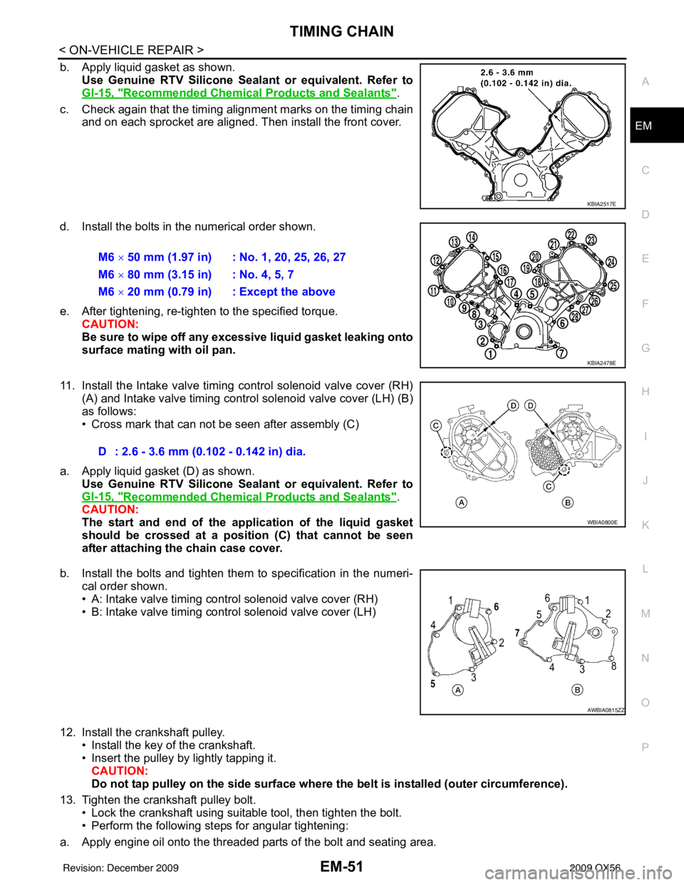
b. Apply liquid gasket as shown.
Use Genuine RTV Silicone Seal ant or equivalent. Refer to
GI-15, "
Recommended Chemical Products and Sealants".
c. Check again that the timing alignment marks on the timing chain and on each sprocket are aligned. Then install the front cover.
d. Install the bolts in the numerical order shown.
e. After tightening, re-tighten to the specified torque. CAUTION:
Be sure to wipe off any excessive liquid gasket leaking onto
surface mating with oil pan.
11. Install the Intake valve timing control solenoid valve cover (RH) (A) and Intake valve timing control solenoid valve cover (LH) (B)
as follows:
• Cross mark that can not be seen after assembly (C)
a. Apply liquid gasket (D) as shown. Use Genuine RTV Silicone Seal ant or equivalent. Refer to
GI-15, "
Recommended Chemical Products and Sealants".
CAUTION:
The start and end of the appl ication of the liquid gasket
should be crossed at a position (C) that cannot be seen
after attaching the chain case cover.
b. Install the bolts and tighten them to specification in the numeri- cal order shown.
• A: Intake valve timing control solenoid valve cover (RH)
• B: Intake valve timing control solenoid valve cover (LH)
12. Install the crankshaft pulley. • Install the key of the crankshaft.
• Insert the pulley by lightly tapping it.
CAUTION:
Do not tap pulley on the side surface where th e belt is installed (outer circumference).
13. Tighten the crankshaft pulley bolt. • Lock the crankshaft using suitable tool, then tighten the bolt.
• Perform the following steps for angular tightening:
a. Apply engine oil onto the threaded parts of the bolt and seating area.
KBIA2517E
M6 × 50 mm (1.97 in) : No. 1, 20, 25, 26, 27
M6 × 80 mm (3.15 in) : No. 4, 5, 7
M6 × 20 mm (0.79 in) : Except the above
KBIA2478E
D : 2.6 - 3.6 mm (0.102 - 0.142 in) dia.
WBIA0800E
AWBIA0815ZZ
Revision: December 20092009 QX56
Page 1885 of 4171
EM-62
< ON-VEHICLE REPAIR >
CAMSHAFT
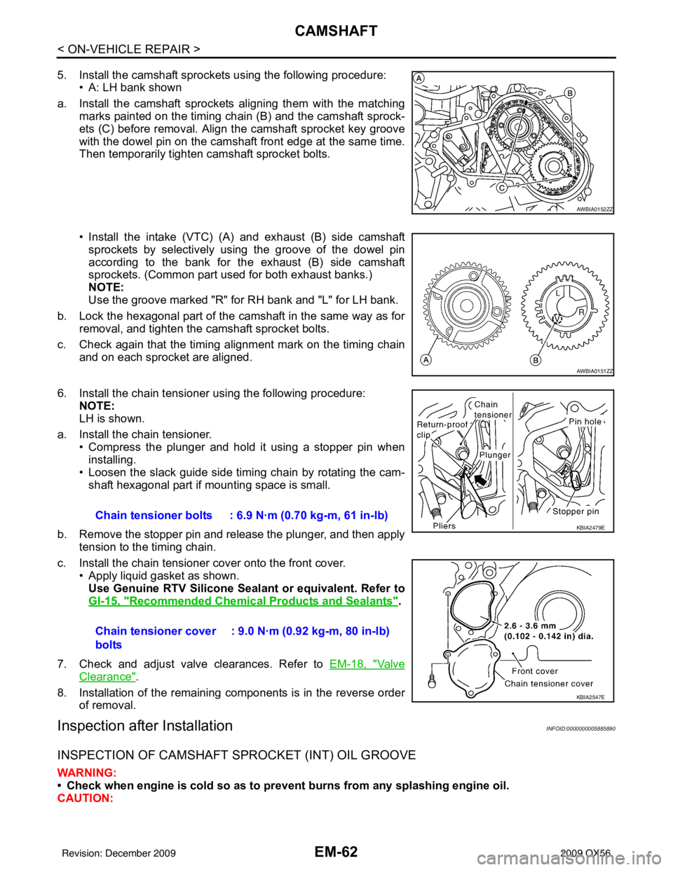
5. Install the camshaft sprockets using the following procedure:• A: LH bank shown
a. Install the camshaft sprockets aligning them with the matching marks painted on the timing chain (B) and the camshaft sprock-
ets (C) before removal. Align the camshaft sprocket key groove
with the dowel pin on the camshaft front edge at the same time.
Then temporarily tighten camshaft sprocket bolts.
• Install the intake (VTC) (A) and exhaust (B) side camshaft
sprockets by selectively using the groove of the dowel pin
according to the bank for the exhaust (B) side camshaft
sprockets. (Common part used for both exhaust banks.)
NOTE:
Use the groove marked "R" for RH bank and "L" for LH bank.
b. Lock the hexagonal part of the camshaft in the same way as for removal, and tighten the camshaft sprocket bolts.
c. Check again that the timing alignment mark on the timing chain and on each sprocket are aligned.
6. Install the chain tensioner using the following procedure: NOTE:
LH is shown.
a. Install the chain tensioner. • Compress the plunger and hold it using a stopper pin wheninstalling.
• Loosen the slack guide side timing chain by rotating the cam- shaft hexagonal part if mounting space is small.
b. Remove the stopper pin and release the plunger, and then apply tension to the timing chain.
c. Install the chain tensioner cover onto the front cover. • Apply liquid gasket as shown.
Use Genuine RTV Silicone Seal ant or equivalent. Refer to
GI-15, "
Recommended Chemical Products and Sealants".
7. Check and adjust valve clearances. Refer to EM-18, "
Va l v e
Clearance".
8. Installation of the remaining components is in the reverse order of removal.
Inspection after InstallationINFOID:0000000005885890
INSPECTION OF CAMSHAFT SPROCKET (INT) OIL GROOVE
WARNING:
• Check when engine is cold so as to pr event burns from any splashing engine oil.
CAUTION:
AWBIA0152ZZ
AWBIA0151ZZ
Chain tensioner bolts : 6.9 N·m (0.70 kg-m, 61 in-lb)
Chain tensioner cover
bolts : 9.0 N·m (0.92 kg-m, 80 in-lb)KBIA2479E
KBIA2547E
Revision: December 20092009 QX56
Page 1905 of 4171
EM-82
< DISASSEMBLY AND ASSEMBLY >
ENGINE UNIT
DISASSEMBLY AND ASSEMBLY
ENGINE UNIT
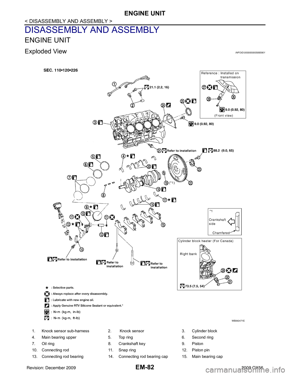
Exploded ViewINFOID:0000000005885901
1. Knock sensor sub-harness 2. Knock sensor3. Cylinder block
4. Main bearing upper 5. Top ring6. Second ring
7. Oil ring 8. Crankshaft key9. Piston
10. Connecting rod 11. Snap ring12. Piston pin
13. Connecting rod bearing 14. Connecting rod bearing cap 15. Main bearing cap
WBIA0471E
Revision: December 20092009 QX56