2009 INFINITI QX56 key fob
[x] Cancel search: key fobPage 1039 of 4171
![INFINITI QX56 2009 Factory Service Manual PREPARATIONDLK-227
< PREPARATION > [WITH INTELLIGENT KEY SYSTEM]
C
D
E
F
G H
I
J
L
M A
B
DLK
N
O P
PREPARATION
PREPARATION
Special Service ToolINFOID:0000000003775849
The actual shapes of Kent-Moore t INFINITI QX56 2009 Factory Service Manual PREPARATIONDLK-227
< PREPARATION > [WITH INTELLIGENT KEY SYSTEM]
C
D
E
F
G H
I
J
L
M A
B
DLK
N
O P
PREPARATION
PREPARATION
Special Service ToolINFOID:0000000003775849
The actual shapes of Kent-Moore t](/manual-img/42/57031/w960_57031-1038.png)
PREPARATIONDLK-227
< PREPARATION > [WITH INTELLIGENT KEY SYSTEM]
C
D
E
F
G H
I
J
L
M A
B
DLK
N
O P
PREPARATION
PREPARATION
Special Service ToolINFOID:0000000003775849
The actual shapes of Kent-Moore tools may differ from those of special service tools illustrated here.
Tool number
(Kent-Moore No.)
Tool name Description
—
(J-39570)
Chassis ear Locating the noise
—
(J-43980)
NISSAN Squeak and Rat-
tle Kit Repairing the cause of noise
—
(J-43241)
Remote Keyless Entry
Te s t e r Used to test keyfobs
SIIA0993E
SIIA0994E
LEL946A
Revision: December 20092009 QX56
Page 2058 of 4171

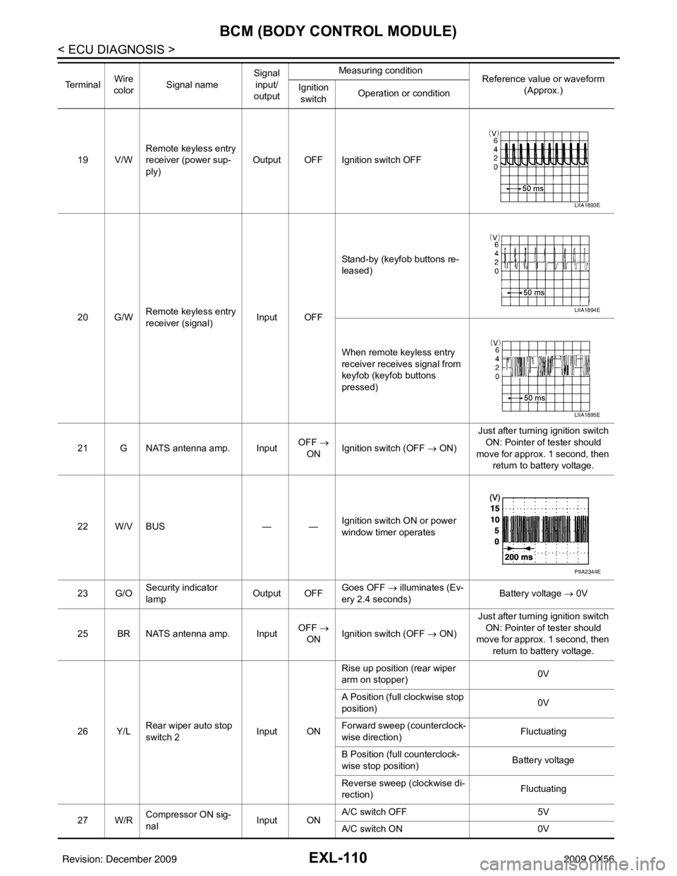
EXL-110
< ECU DIAGNOSIS >
BCM (BODY CONTROL MODULE)
19 V/WRemote keyless entry
receiver (power sup-
ply) Output OFF Ignition switch OFF
20 G/W Remote keyless entry
receiver (signal) Input OFFStand-by (keyfob buttons re-
leased)
When remote keyless entry
receiver receives signal from
keyfob (keyfob buttons
pressed)
21 G NATS antenna amp. Input OFF
→
ON Ignition switch (OFF
→ ON)Just after turning ignition switch
ON: Pointer of tester should
move for approx. 1 second, then return to battery voltage.
22 W/V BUS — —Ignition switch ON or power
window timer operates
23 G/O Security indicator
lamp Output OFF
Goes OFF
→ illuminates (Ev-
ery 2.4 seconds) Battery voltage
→ 0V
25 BR NATS antenna amp. Input OFF
→
ON Ignition switch (OFF
→ ON)Just after turning ignition switch
ON: Pointer of tester should
move for approx. 1 second, then return to battery voltage.
26 Y/L Rear wiper auto stop
switch 2 Input ONRise up position (rear wiper
arm on stopper)
0V
A Position (full clockwise stop
position) 0V
Forward sweep (counterclock-
wise direction) Fluctuating
B Position (full counterclock-
wise stop position) Battery voltage
Reverse sweep (clockwise di-
rection) Fluctuating
27 W/R Compressor ON sig-
nal Input ONA/C switch OFF
5V
A/C switch ON 0V
Te r m i n a l
Wire
color Signal name Signal
input/
output Measuring condition
Reference value or waveform
(Approx.)
Ignition
switch Operation or condition
LIIA1893E
LIIA1894E
LIIA1895E
PIIA2344E
Revision: December 20092009 QX56
Page 2074 of 4171

EXL-126
< ECU DIAGNOSIS >
IPDM E/R (INTELLIGENT POWER DISTRIBUTION MODULE ENGINE ROOM)
41 Y/B Hood switch Input —Hood closed OFF
0V
Hood open ON Battery voltage
42 GR Oil pressure switch Input — Engine running
Battery voltage
Engine stopped 0V
43 L/Y Wiper auto stop signal Input ON or
START Wiper switch OFF, LO, INT Battery voltage
44 BR Daytime light relay
control Input ONDaytime light system active
0V
Daytime light system inactive Battery voltage
45 G/W Horn relay control Input ON When door locks are operated
using keyfob or Intelligent Key
(OFF
→ ON)* Battery voltage
→ 0V
46 GR Fuel pump relay con-
trol
Input —Ignition switch ON or START
0V
Ignition switch OFF or ACC Battery voltage
47 O Throttle control motor
relay control
Input —Ignition switch ON or START
0V
Ignition switch OFF or ACC Battery voltage
48 B/R Starter relay (inhibit
switch) InputON or
START Selector lever in "P" or "N"
0V
Selector lever any other posi-
tion Battery voltage
49 R/L Trailer tow relay Output ON Lighting
switch must
be in the 1st
positionOFF
0V
ON Battery voltage
50 W/R Front fog lamp (LH) Output ON or
START Lighting
switch must
be in the 2nd
position
(LOW beam
is ON) and
the front fog
lamp switch OFF
0V
ON Battery voltage
51 W/R Front fog lamp (RH) Output ON or
START Lighting
switch must
be in the 2nd
position
(LOW beam
is ON) and
the front fog
lamp switch OFF
0V
ON Battery voltage
52 L LH low beam head-
lamp Output — Lighting switch in 2nd position Battery voltage
54 R/Y RH low beam head-
lamp Output — Lighting switch in 2nd position Battery voltage
55 G LH high beam head-
lamp Output —Lighting switch in 2nd position
and placed in HIGH or PASS
position Battery voltage
56 L/W RH high beam head-
lamp Output —Lighting switch in 2nd position
and placed in HIGH or PASS
position Battery voltage
57 R/L Parking, license, and
tail lamp
Output ONLighting
swi
t
ch 1st po-
sition OFF
0V
ON Battery voltage
Te r m i n a l
Wire
color Signal name Signal
input/
output Measuring condition
Reference value(Approx.)
Igni-
tion
switch Operation or condition
Revision: December 20092009 QX56
Page 2503 of 4171

BCM (BODY CONTROL MODULE)INL-59
< ECU DIAGNOSIS >
C
DE
F
G H
I
J
K
M A
B
INL
N
O P
19 V/W Remote keyless entry
receiver (power sup-
ply) Output OFF Ignition switch OFF
20 G/W Remote keyless entry
receiver (signal) Input OFFStand-by (keyfob buttons re-
leased)
When remote keyless entry
receiver receives signal from
keyfob (keyfob buttons
pressed)
21 G NATS antenna amp. Input OFF
→
ON Ignition switch (OFF → ON) Just after turning ignition switch
ON: Pointer of tester should
move for approx. 1 second, then return to battery voltage.
22 W/V BUS — —Ignition switch ON or power
window timer operates
23 G/O Security indicator
lamp Output OFF
Goes OFF
→ illuminates (Ev-
ery 2.4 seconds) Battery voltage
→ 0V
25 BR NATS antenna amp. Input OFF
→
ON Ignition switch (OFF → ON) Just after turning ignition switch
ON: Pointer of tester should
move for approx. 1 second, then return to battery voltage.
26 Y/L Rear wiper auto stop
switch 2 Input ONRise up position (rear wiper
arm on stopper)
0V
A Position (full clockwise stop
position) 0V
Forward sweep (counterclock-
wise direction) Fluctuating
B Position (full counterclock-
wise stop position) Battery voltage
Reverse sweep (clockwise di-
rection) Fluctuating
27 W/R Compressor ON sig-
nal Input ONA/C switch OFF
5V
A/C switch ON 0V
Te r m i n a l
Wire
color Signal name Signal
input/
output Measuring condition
Reference value or waveform
(Approx.)
Ignition
switch Operation or condition
LIIA1893E
LIIA1894E
LIIA1895E
PIIA2344E
Revision: December 20092009 QX56
Page 2614 of 4171
![INFINITI QX56 2009 Factory Service Manual LAN
CAN COMMUNICATION SYSTEMLAN-45
< FUNCTION DIAGNOSIS > [CAN]
C
D
E
F
G H
I
J
K L
B A
O P
N
Engine speed signal
T RRR R R R R R
Engine status signal TR
Fuel consumption monitor signal TR
RT
ICC stee INFINITI QX56 2009 Factory Service Manual LAN
CAN COMMUNICATION SYSTEMLAN-45
< FUNCTION DIAGNOSIS > [CAN]
C
D
E
F
G H
I
J
K L
B A
O P
N
Engine speed signal
T RRR R R R R R
Engine status signal TR
Fuel consumption monitor signal TR
RT
ICC stee](/manual-img/42/57031/w960_57031-2613.png)
LAN
CAN COMMUNICATION SYSTEMLAN-45
< FUNCTION DIAGNOSIS > [CAN]
C
D
E
F
G H
I
J
K L
B A
O P
N
Engine speed signal
T RRR R R R R R
Engine status signal TR
Fuel consumption monitor signal TR
RT
ICC steering switch signal TR
Malfunction indicator lamp signal T R
Wide open throttle position signal T R
A/T CHECK indicato r lamp signal T R
A/T fluid temperature sensor signal T R
A/T position indicator lamp signal TR RR
A/T self-diagnosis signal R T
Current gear position signal TR R
Input speed signal R TR
Output shaft revolution signal R TR R
P range signal TR R RR
ICC sensor signal T R
Buzzer output signal TR
TR
ICC OD cancel request signal R RT
ICC operation signal R RT
ICC system display signal TR
System setting signal TRT
RTR
A/C switch/indicator signal TR
RT
A/C switch signal RT R
Blower fan motor switch signal RT
Day time running light request signal TR R
Door lock/unlock status signal TR
Door switch signal R R TR R R
Front fog light request signal TR
Front wiper request signal RT R
High beam request signal TR R
Horn chirp signal TR
Ignition switch signal RTR R
Key fob door unlock signal RT
Key fob ID signal RT
Key switch signal RT
Low beam request signal TR
Position light request signal TR R
Rear window defogger switch signal T RR
Sleep wake up signal RT R R
Theft warning horn request signal TR
Signal name/Connecting unit
ECM
TCM
LASER ICC
ADP AV
BCM
HVAC I-KEY M&A
STRG 4WD
ABS
IPDM-E
Revision: December 20092009 QX56
Page 2790 of 4171

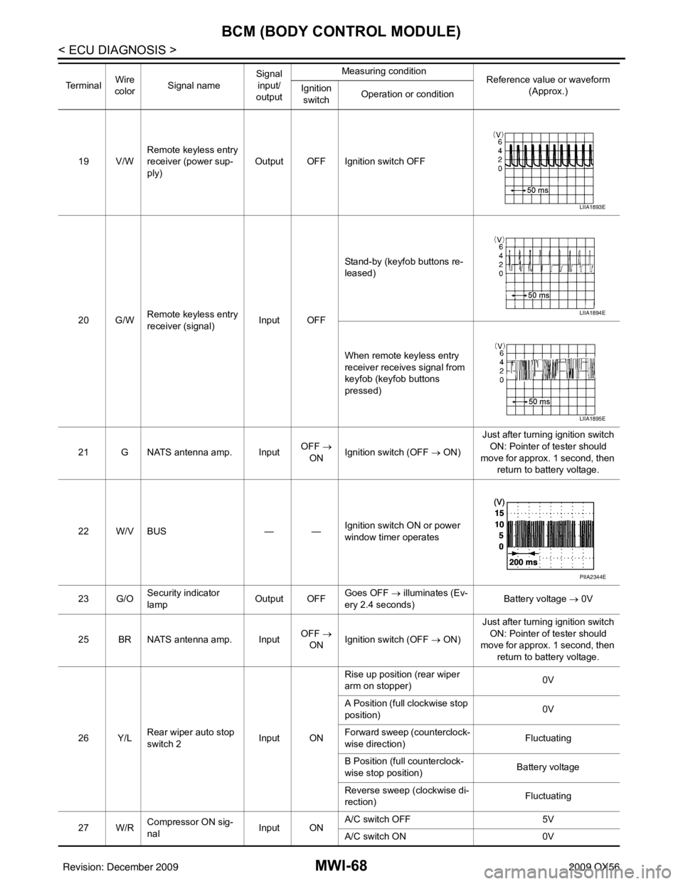
MWI-68
< ECU DIAGNOSIS >
BCM (BODY CONTROL MODULE)
19 V/WRemote keyless entry
receiver (power sup-
ply) Output OFF Ignition switch OFF
20 G/W Remote keyless entry
receiver (signal) Input OFFStand-by (keyfob buttons re-
leased)
When remote keyless entry
receiver receives signal from
keyfob (keyfob buttons
pressed)
21 G NATS antenna amp. Input OFF
→
ON Ignition switch (OFF
→ ON)Just after turning ignition switch
ON: Pointer of tester should
move for approx. 1 second, then return to battery voltage.
22 W/V BUS — —Ignition switch ON or power
window timer operates
23 G/O Security indicator
lamp Output OFF
Goes OFF
→ illuminates (Ev-
ery 2.4 seconds) Battery voltage
→ 0V
25 BR NATS antenna amp. Input OFF
→
ON Ignition switch (OFF
→ ON)Just after turning ignition switch
ON: Pointer of tester should
move for approx. 1 second, then return to battery voltage.
26 Y/L Rear wiper auto stop
switch 2 Input ONRise up position (rear wiper
arm on stopper)
0V
A Position (full clockwise stop
position) 0V
Forward sweep (counterclock-
wise direction) Fluctuating
B Position (full counterclock-
wise stop position) Battery voltage
Reverse sweep (clockwise di-
rection) Fluctuating
27 W/R Compressor ON sig-
nal Input ONA/C switch OFF
5V
A/C switch ON 0V
Te r m i n a l
Wire
color Signal name Signal
input/
output Measuring condition
Reference value or waveform
(Approx.)
Ignition
switch Operation or condition
LIIA1893E
LIIA1894E
LIIA1895E
PIIA2344E
Revision: December 20092009 QX56
Page 3006 of 4171

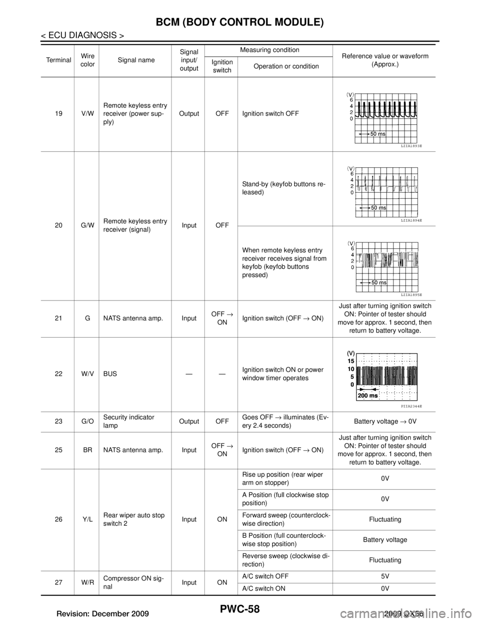
PWC-58
< ECU DIAGNOSIS >
BCM (BODY CONTROL MODULE)
19 V/WRemote keyless entry
receiver (power sup-
ply) Output OFF Ignition switch OFF
20 G/W Remote keyless entry
receiver (signal) Input OFFStand-by (keyfob buttons re-
leased)
When remote keyless entry
receiver receives signal from
keyfob (keyfob buttons
pressed)
21 G NATS antenna amp. Input OFF
→
ON Ignition switch (OFF
→ ON) Just after turning ignition switch
ON: Pointer of tester should
move for approx. 1 second, then return to battery voltage.
22 W/V BUS — — Ignition switch ON or power
window timer operates
23 G/O Security indicator
lamp Output OFF
Goes OFF
→ illuminates (Ev-
ery 2.4 seconds) Battery voltage
→ 0V
25 BR NATS antenna amp. Input OFF
→
ON Ignition switch (OFF
→ ON) Just after turning ignition switch
ON: Pointer of tester should
move for approx. 1 second, then return to battery voltage.
26 Y/L Rear wiper auto stop
switch 2 Input ONRise up position (rear wiper
arm on stopper)
0V
A Position (full clockwise stop
position) 0V
Forward sweep (counterclock-
wise direction) Fluctuating
B Position (full counterclock-
wise stop position) Battery voltage
Reverse sweep (clockwise di-
rection) Fluctuating
27 W/R Compressor ON sig-
nal Input ONA/C switch OFF 5V
A/C switch ON 0V
Te r m i n a l
Wire
color Signal name Signal
input/
output Measuring condition
Reference value or waveform
(Approx.)
Ignition
switch Operation or condition
LIIA1893E
LIIA1894E
LIIA1895E
PIIA2344E
Revision: December 20092009 QX56
Page 3111 of 4171

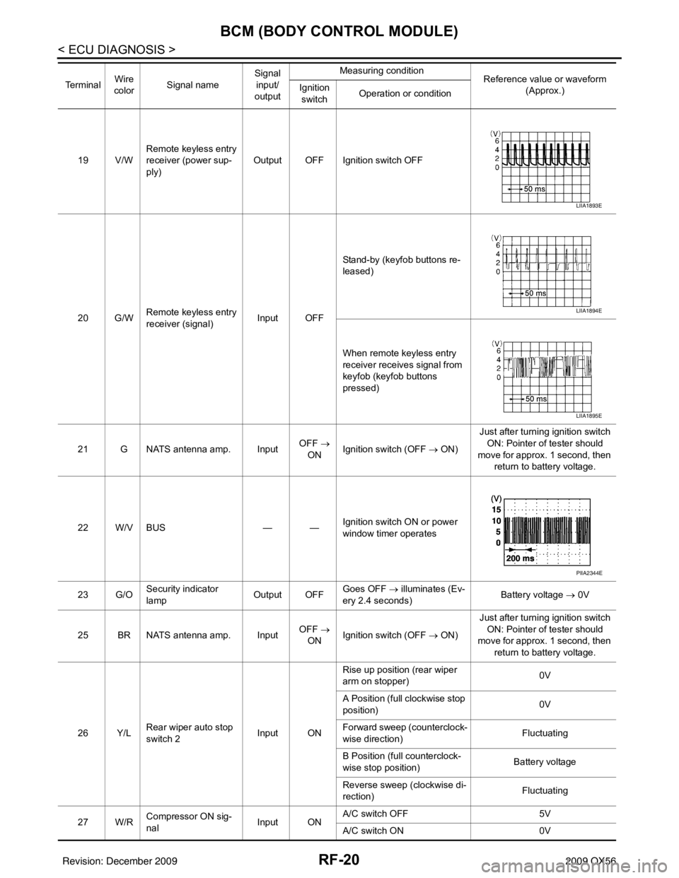
RF-20
< ECU DIAGNOSIS >
BCM (BODY CONTROL MODULE)
19 V/WRemote keyless entry
receiver (power sup-
ply) Output OFF Ignition switch OFF
20 G/W Remote keyless entry
receiver (signal) Input OFFStand-by (keyfob buttons re-
leased)
When remote keyless entry
receiver receives signal from
keyfob (keyfob buttons
pressed)
21 G NATS antenna amp. Input OFF
→
ON Ignition switch (OFF
→ ON)Just after turning ignition switch
ON: Pointer of tester should
move for approx. 1 second, then return to battery voltage.
22 W/V BUS — —Ignition switch ON or power
window timer operates
23 G/O Security indicator
lamp Output OFF
Goes OFF
→ illuminates (Ev-
ery 2.4 seconds) Battery voltage
→ 0V
25 BR NATS antenna amp. Input OFF
→
ON Ignition switch (OFF
→ ON)Just after turning ignition switch
ON: Pointer of tester should
move for approx. 1 second, then return to battery voltage.
26 Y/L Rear wiper auto stop
switch 2 Input ONRise up position (rear wiper
arm on stopper)
0V
A Position (full clockwise stop
position) 0V
Forward sweep (counterclock-
wise direction) Fluctuating
B Position (full counterclock-
wise stop position) Battery voltage
Reverse sweep (clockwise di-
rection) Fluctuating
27 W/R Compressor ON sig-
nal Input ONA/C switch OFF
5V
A/C switch ON 0V
Te r m i n a l
Wire
color Signal name Signal
input/
output Measuring condition
Reference value or waveform
(Approx.)
Ignition
switch Operation or condition
LIIA1893E
LIIA1894E
LIIA1895E
PIIA2344E
Revision: December 20092009 QX56