Page 2940 of 4171

PG
HARNESS CONNECTORPG-69
< COMPONENT DIAGNOSIS >
C
DE
F
G H
I
J
K L
B A
O P
N
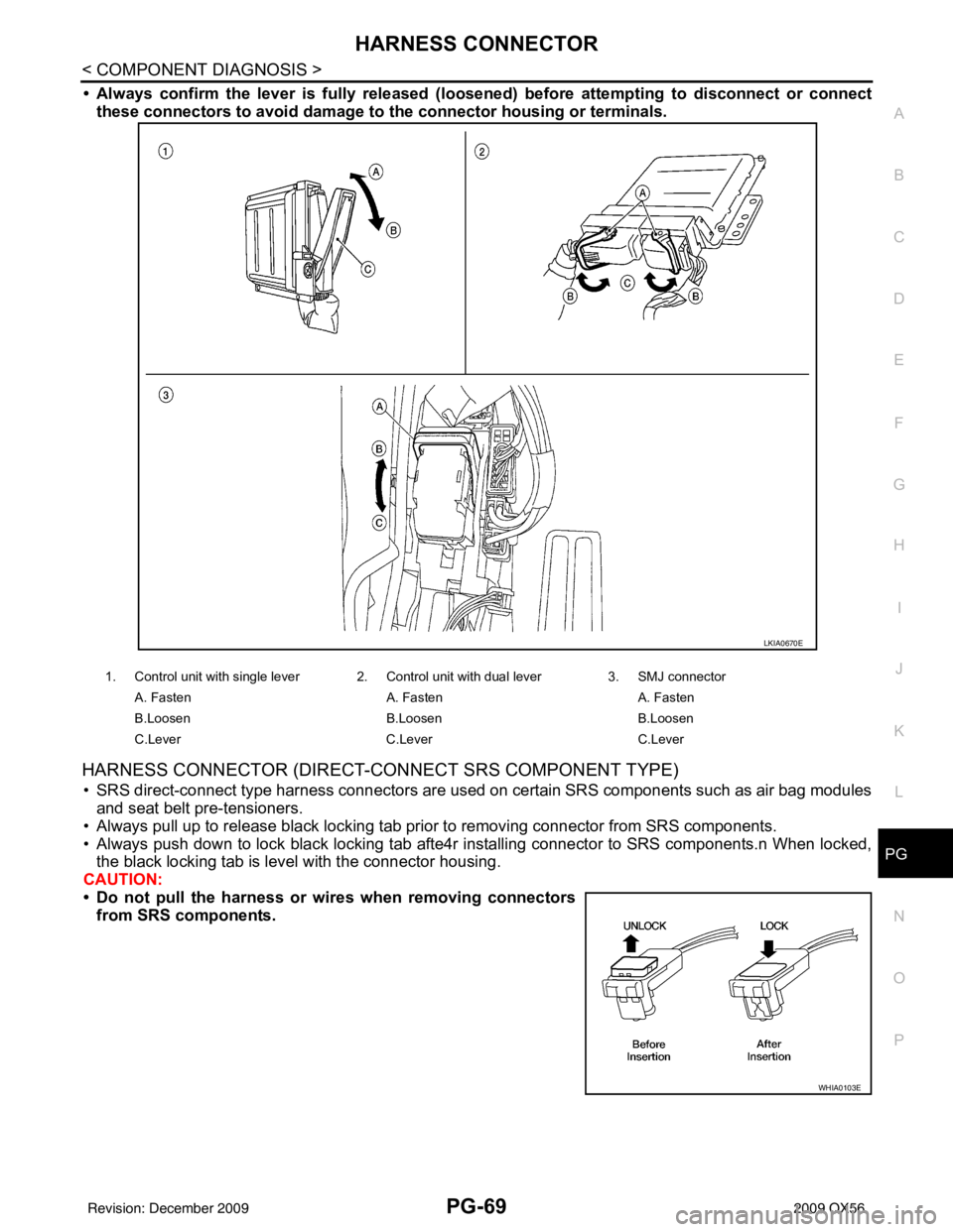
• Always confirm the lever is full
y released (loosened) before attempting to disconnect or connect
these connectors to avoid damage to the connector housing or terminals.
HARNESS CONNECTOR (DIRECT-CONNECT SRS COMPONENT TYPE)
• SRS direct-connect type harness connectors are used on certain SRS components such as air bag modules
and seat belt pre-tensioners.
• Always pull up to release black locking tab prior to removing connector from SRS components.
• Always push down to lock black locking tab afte4r installing connector to SRS components.n When locked, the black locking tab is level with the connector housing.
CAUTION:
• Do not pull the harness or wir es when removing connectors
from SRS components.
1. Control unit with single lever 2. Control unit with dual lever 3. SMJ connector
A. Fasten A. FastenA. Fasten
B.Loosen B.LoosenB.Loosen
C.Lever C.Lever C.Lever
LKIA0670E
WHIA0103E
Revision: December 20092009 QX56
Page 2941 of 4171
PG-70
< COMPONENT DIAGNOSIS >
STANDARDIZED RELAY
STANDARDIZED RELAY
DescriptionINFOID:0000000003776574
NORMAL OPEN, NORMAL CLOSED AND MIXED TYPE RELAYS
Relays can mainly be divided into three types: normal open, normal closed and mixed type relays.
TYPE OF STANDARDIZED RELAYS
SEL881H
1M ···················· 1 Make 2M ···················· 2 Make
1T ···················· 1 Transfer 1M·1B ···················· 1 Make 1 Break
SEL882H
Revision: December 20092009 QX56
Page 2942 of 4171
PG
STANDARDIZED RELAYPG-71
< COMPONENT DIAGNOSIS >
C
DE
F
G H
I
J
K L
B A
O P
N
SEL188W
Revision: December 20092009 QX56
Page 2943 of 4171
PG-72
< COMPONENT DIAGNOSIS >
FUSE BLOCK - JUNCTION BOX (J/B)
FUSE BLOCK - JUNCTION BOX (J/B)
Terminal ArrangementINFOID:0000000003776575
AWMIA0898GB
Revision: December 20092009 QX56
Page 2944 of 4171
PG
FUSE, FUSIBLE LINK AND RELAY BOXPG-73
< COMPONENT DIAGNOSIS >
C
DE
F
G H
I
J
K L
B A
O P
N
FUSE, FUSIBLE LINK AND RELAY BOX
Terminal ArrangementINFOID:0000000003776576
FUSE AND FUSIBLE LINK BOX
ABMIA0136GB
Revision: December 20092009 QX56
Page 2945 of 4171
PG-74
< COMPONENT DIAGNOSIS >
FUSE, FUSIBLE LINK AND RELAY BOX
FUSE AND RELAY BOX
ABMIA0166GB
Revision: December 20092009 QX56
Page 2946 of 4171
PG
IPDM E/R (INTELLIGENT POWER DISTRIBUTION MODULE ENGINE ROOM)
PG-75
< COMPONENT DIAGNOSIS >
C
D E
F
G H
I
J
K L
B A
O P
N
IPDM E/R (INTELLIGENT POWER
DISTRIBUTION MODULE ENGINE
ROOM)
IPDM E/R Terminal Arrangement INFOID:0000000005783139
WKIA5852E
Revision: December 20092009 QX56
Page 2947 of 4171
PG-76
< ON-VEHICLE REPAIR >
BATTERY
ON-VEHICLE REPAIR
BATTERY
Removal and InstallationINFOID:0000000003776577
REMOVAL
1. Disconnect the negative battery terminal (1) and positive batteryterminal (2).
CAUTION:
Remove negative battery terminal first.
2. Remove the battery cover.
3. Remove the battery clamp bolt (3) and battery clamp.
4. Remove the battery.
INSTALLATION
Installation is in the reverse order of removal.
CAUTION:
When installing, install the po sitive battery terminal first.
Reset electronic systems as necessary. Refer to PG-8, "
ADDITIONAL SERVICE WHEN REMOVING BAT-
TERY NEGATIVE TERMINAL : Special Repair Requirement".
: Front
AWBIA0504ZZ
Battery clamp bolt : 14.7 N·m (1.5 kg-m, 11 ft-lb)
Battery terminal nut : 3.5 N·m (0.36 kg-m, 31 in-lb)
Revision: December 20092009 QX56