2009 INFINITI QX56 battery location
[x] Cancel search: battery locationPage 1981 of 4171
HEADLAMP (HI) CIRCUITEXL-33
< COMPONENT DIAGNOSIS >
C
DE
F
G H
I
J
K
M A
B
EXL
N
O P
NO >> GO TO 3.
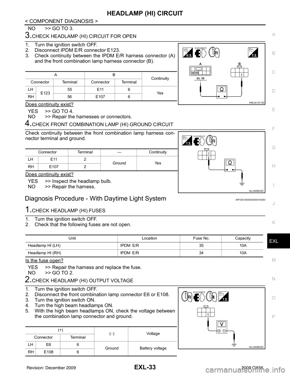
3.CHECK HEADLAMP (HI) CIRCUIT FOR OPEN
1. Turn the ignition switch OFF.
2. Disconnect IPDM E/R connector E123.
3. Check continuity between the IPDM E/R harness connector (A) and the front combination lamp harness connector (B).
Does continuity exist?
YES >> GO TO 4.
NO >> Repair the harnesses or connectors.
4.CHECK FRONT COMBINATION LAMP (HI) GROUND CIRCUIT
Check continuity between the front combination lamp harness con-
nector terminal and ground.
Does continuity exist?
YES >> Inspect the headlamp bulb.
NO >> Repair the harness.
Diagnosis Procedure - With Daytime Light SystemINFOID:0000000004216293
1.CHECK HEADLAMP (HI) FUSES
1. Turn the ignition switch OFF.
2. Check that the following fuses are not open.
Is the fuse open?
YES >> Repair the harness and replace the fuse.
NO >> GO TO 2.
2.CHECK HEADLAMP (HI) OUTPUT VOLTAGE
1. Turn the ignition switch OFF.
2. Disconnect the front combination lamp connector E6 or E108.
3. Turn the ignition switch ON.
4. Turn the high beam headlamps ON.
5. With the high beam headlamps ON, check the voltage between the combination lamp connector and ground.
AB Continuity
Connector Terminal Connector Terminal
LH E123 55
E11 6
Ye s
RH 56E107 6
AWLIA1371ZZ
Connector Terminal —Continuity
LH E11 2
Ground Yes
RH E107 2
ALLIA0854ZZ
Unit LocationFuse No.Capacity
Headlamp HI (LH) IPDM E/R3510A
Headlamp HI (RH) IPDM E/R3410A
(+)
(−)Voltage
Connector Terminal
LH E6 6 Ground Battery voltage
RH E108 6
ALLIA0852ZZ
Revision: December 20092009 QX56
Page 1983 of 4171
HEADLAMP (LO) CIRCUITEXL-35
< COMPONENT DIAGNOSIS >
C
DE
F
G H
I
J
K
M A
B
EXL
N
O P
HEADLAMP (LO) CIRCUIT
DescriptionINFOID:0000000003776181
The IPDM E/R (intelligent power distribution modul e engine room) controls the headlamp low relay based on
inputs from the BCM via the CAN communication li nes. When the headlamp low relay is energized, power
flows through fuses 40 and 41, located in the IPDM E/R. Power then flows to the front combination lamps to
the headlamp low beam.
Component Function CheckINFOID:0000000003776182
1.CHECK HEADLAMP (LO) OPERATION
WITHOUT CONSULT-III
1. Start IPDM E/R auto active test. Refer to PCS-12, "
Diagnosis Description".
2. Check that the headlamp is turned ON. NOTE:
HI/LO is repeated 1 second each when using the IPDM E/R auto active test.
CONSULT-III
1. Select "EXTERNAL LAMP" of IPDM E/R active test item.
2. With the test items operating, c heck that the headlamp is turned ON.
Is the headlamp turned ON?
YES >> Headlamp (LO) is normal.
NO >> Refer to EXL-35, "
Diagnosis Procedure - Without Daytime Light System", EXL-36, "Diagnosis
Procedure - With Daytime Light System".
Diagnosis Procedure - Without Daytime Light SystemINFOID:0000000003776183
1.CHECK HEADLAMP (LO) FUSES
1. Turn the ignition switch OFF.
2. Check that the following fuses are not open.
Is the fuse open?
YES >> Repair the harness and replace the fuse.
NO >> GO TO 2.
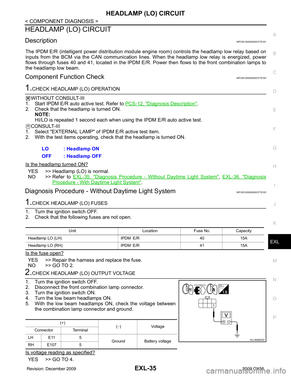
2.CHECK HEADLAMP (LO) OUTPUT VOLTAGE
1. Turn the ignition switch OFF.
2. Disconnect the front combination lamp connector.
3. Turn the ignition switch ON.
4. Turn the low beam headlamps ON.
5. With the low beam headlamps ON, check the voltage between the combination lamp connector and ground.
Is voltage reading as specified?
YES >> GO TO 4. LO : Headlamp ON
OFF : Headlamp OFF
Unit
LocationFuse No.Capacity
Headlamp LO (LH) IPDM E/R4015A
Headlamp LO (RH) IPDM E/R4115A
(+)
(−)Voltage
Connector Terminal
LH E11 5
Ground Battery voltage
RH E107 5
ALLIA0855ZZ
Revision: December 20092009 QX56
Page 1984 of 4171
EXL-36
< COMPONENT DIAGNOSIS >
HEADLAMP (LO) CIRCUIT
NO >> GO TO 3.
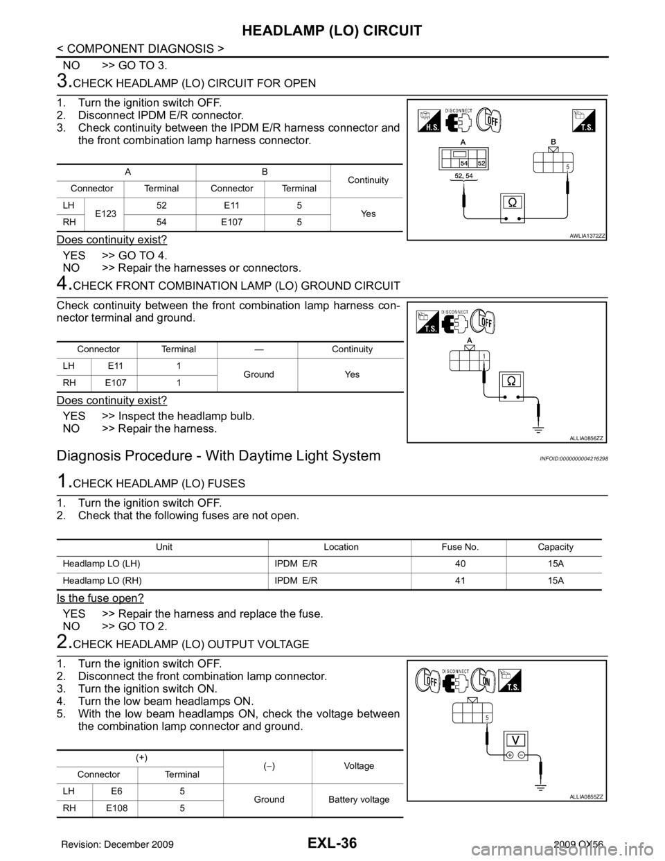
3.CHECK HEADLAMP (LO) CIRCUIT FOR OPEN
1. Turn the ignition switch OFF.
2. Disconnect IPDM E/R connector.
3. Check continuity between the IPDM E/R harness connector and
the front combination lamp harness connector.
Does continuity exist?
YES >> GO TO 4.
NO >> Repair the harnesses or connectors.
4.CHECK FRONT COMBINATION LAMP (LO) GROUND CIRCUIT
Check continuity between the front combination lamp harness con-
nector terminal and ground.
Does continuity exist?
YES >> Inspect the headlamp bulb.
NO >> Repair the harness.
Diagnosis Procedure - With Daytime Light SystemINFOID:0000000004216298
1.CHECK HEADLAMP (LO) FUSES
1. Turn the ignition switch OFF.
2. Check that the following fuses are not open.
Is the fuse open?
YES >> Repair the harness and replace the fuse.
NO >> GO TO 2.
2.CHECK HEADLAMP (LO) OUTPUT VOLTAGE
1. Turn the ignition switch OFF.
2. Disconnect the front combination lamp connector.
3. Turn the ignition switch ON.
4. Turn the low beam headlamps ON.
5. With the low beam headlamps ON, check the voltage between the combination lamp connector and ground.
AB Continuity
Connector Terminal Connector Terminal
LH E123 52
E11 5
Ye s
RH 54E107 5
AWLIA1372ZZ
Connector Terminal —Continuity
LH E11 1
Ground Yes
RH E107 1
ALLIA0856ZZ
Unit LocationFuse No.Capacity
Headlamp LO (LH) IPDM E/R4015A
Headlamp LO (RH) IPDM E/R4115A
(+)
(−)V olt a ge
Connector Terminal
LH E6 5
Ground Battery voltage
RH E108 5
ALLIA0855ZZ
Revision: December 20092009 QX56
Page 1986 of 4171
EXL-38
< COMPONENT DIAGNOSIS >
FRONT FOG LAMP CIRCUIT
FRONT FOG LAMP CIRCUIT
DescriptionINFOID:0000000003776184
The IPDM E/R (intelligent power distribution module engine room) controls the front fog lamp relay based on
inputs from the BCM via the CAN communication lines. When the front fog lamp relay is energized, power
flows from the front fog lamp relay in the IPDM E/R to the front fog lamps.
Component Function CheckINFOID:0000000003776185
1.CHECK FRONT FOG LAMP OPERATION
WITHOUT CONSULT-III
1. Activate IPDM E/R auto active test. Refer to PCS-12, "
Diagnosis Description".
2. Check that the front fog lamp is turned ON.
CONSULT-III
1. Select "EXTERNAL LAMP" of IPDM E/R active test item.
2. With operating the test items, Check that the front fog lamp is turned ON.
Is the front fog lamp turned ON?
YES >> Front fog lamp circuit is normal.
NO >> Refer to EXL-38, "
Diagnosis Procedure".
Diagnosis ProcedureINFOID:0000000003776186
1.CHECK FRONT FOG LAMP FUSE
1. Turn the ignition switch OFF.
2. Check that the following fuses are not open.
Is the fuse open?
YES >> Repair the harness and replace the fuse.
NO >> GO TO 2.
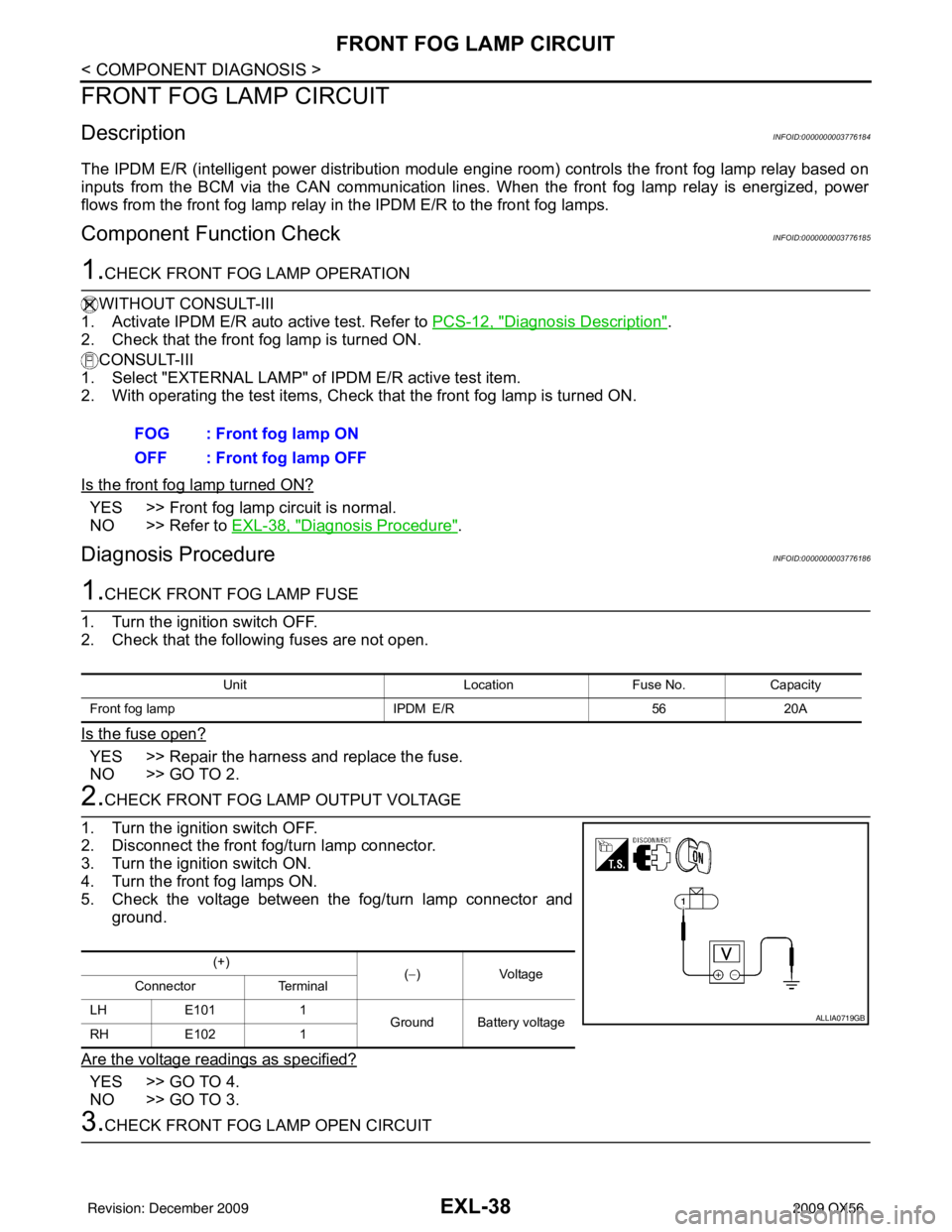
2.CHECK FRONT FOG LAMP OUTPUT VOLTAGE
1. Turn the ignition switch OFF.
2. Disconnect the front fog/turn lamp connector.
3. Turn the ignition switch ON.
4. Turn the front fog lamps ON.
5. Check the voltage between the fog/turn lamp connector and ground.
Are the voltage readings as specified?
YES >> GO TO 4.
NO >> GO TO 3.
3.CHECK FRONT FOG LAMP OPEN CIRCUIT FOG : Front fog lamp ON
OFF : Front fog lamp OFF
Unit
LocationFuse No.Capacity
Front fog lamp IPDM E/R5620A
(+)
(−)V olt a g e
Connector Terminal
LH E101 1
Ground Battery voltage
RH E102 1
ALLIA0719GB
Revision: December 20092009 QX56
Page 1988 of 4171
EXL-40
< COMPONENT DIAGNOSIS >
PARKING LAMP CIRCUIT
PARKING LAMP CIRCUIT
DescriptionINFOID:0000000003776187
The IPDM E/R (intelligent power distribution module engine room) controls the tail lamp relay based on inputs
from the BCM via the CAN communication lines. When the tail lamp relay is energized, power flows through
fuse 37, located in the IPDM E/R. Power then flows to the front and rear combination lamps.
Component Function CheckINFOID:0000000003776188
1.CHECK PARKING LAMP OPERATION
WITHOUT CONSULT-III
1. Activate IPDM E/R auto active test. Refer to PCS-12, "
Diagnosis Description".
2. Check that the parking lamp is turned ON.
CONSULT-III
1. Select "EXTERNAL LAMP" of IPDM E/R active test item.
2. With operating the test items, check that the parking lamp is turned ON.
Is the parking lamp turned ON?
YES >> Parking lamp circuit is normal.
NO >> Refer to EXL-40, "
Diagnosis Procedure - Without Daytime Light System", EXL-42, "Diagnosis
Procedure - With Daytime Light System".
Diagnosis Procedure - Wit hout Daytime Light SystemINFOID:0000000003776189
1.CHECK PARKING LAMP FUSES
1. Turn the ignition switch OFF.
2. Check that the following fuses are not open.
Is the fuse open?
YES >> Repair the harness and replace the fuse.
NO >> GO TO 2.
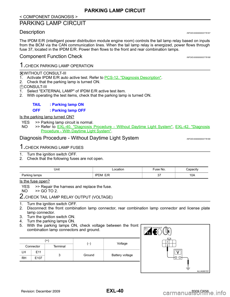
2.CHECK TAIL LAMP RELAY OUTPUT (VOLTAGE)
1. Turn the ignition switch OFF.
2. Disconnect the front combination lamp connector, rear combination lamp connector and license plate
lamp connector.
3. Turn the ignition switch ON.
4. Turn the parking lamps ON.
5. With the parking lamps ON, check voltage between the front combination lamp connectors and ground.TAIL : Parking lamp ON
OFF : Parking lamp OFF
Unit
LocationFuse No.Capacity
Parking lamps IPDM E/R3710A
(+)
(−)V olt a ge
Connector Terminal
LH E11 3Ground Battery voltage
RH E107
ALLIA0857ZZ
Revision: December 20092009 QX56
Page 2140 of 4171

PRECAUTIONSFAX-3
< PRECAUTION >
CEF
G H
I
J
K L
M A
B
FA X
N
O P
5. When the repair work is completed, return the ignition switch to the ″LOCK ″ position before connecting
the battery cables. (At this time, the steering lock mechanism will engage.)
6. Perform a self-diagnosis check of al l control units using CONSULT-III.
PrecautionINFOID:0000000003772244
Observe the following precautions when disassembling and servicing the wheel hub and drive shafts.
Perform work in a location which is as dust-free as possible.
Before disassembling and servicing, clean the outside of parts.
Prevention of the entry of foreign objects must be taken into account during disassembly of the component
parts.
Disassembled parts must be carefully reassembled in t he correct order. If work is interrupted, a clean cover
must be placed over parts.
Paper shop cloths must be used. Fabric shop cloths must not be used because of the danger of lint adhering
to parts.
Disassembled parts (except for rubber parts) should be cleaned with a suitable solvent which shall be removed by blowing with air or wiping with paper shop cloths.
Revision: December 20092009 QX56
Page 2200 of 4171
GI-6
< HOW TO USE THIS MANUAL >
HOW TO FOLLOW TROUBLE DIAGNOSES
HOW TO FOLLOW TROUBLE DIAGNOSES
DescriptionINFOID:0000000003771179
NOTICE:
Trouble diagnoses indicate work procedures required to diagnose problems effectively. Observe the following
instructions before diagnosing.
• Before performing trouble diagnoses, read the “Work Flow” in each section.
• After repairs, re-check that the problem has been completely eliminated.
• Refer to Component Parts and Harness Connector Location for the Systems described in each section for
identification/location of components and harness connectors.
• When checking circuit continuity, ignition switch should be OFF.
• Refer to the Circuit Diagram for quick pinpoint check. If you need to check circuit continui ty between harness connectors in more detail, such as when a sub-har-
ness is used, refer to Wiring Diagram in each individual section and Harness Layout in PG section for identi-
fication of harness connectors.
• Before checking voltage at connectors, check battery voltage.
• After accomplishing the Diagnosis Procedures and Elec trical Components Inspection, make sure that all
harness connectors are reconnected as they were.
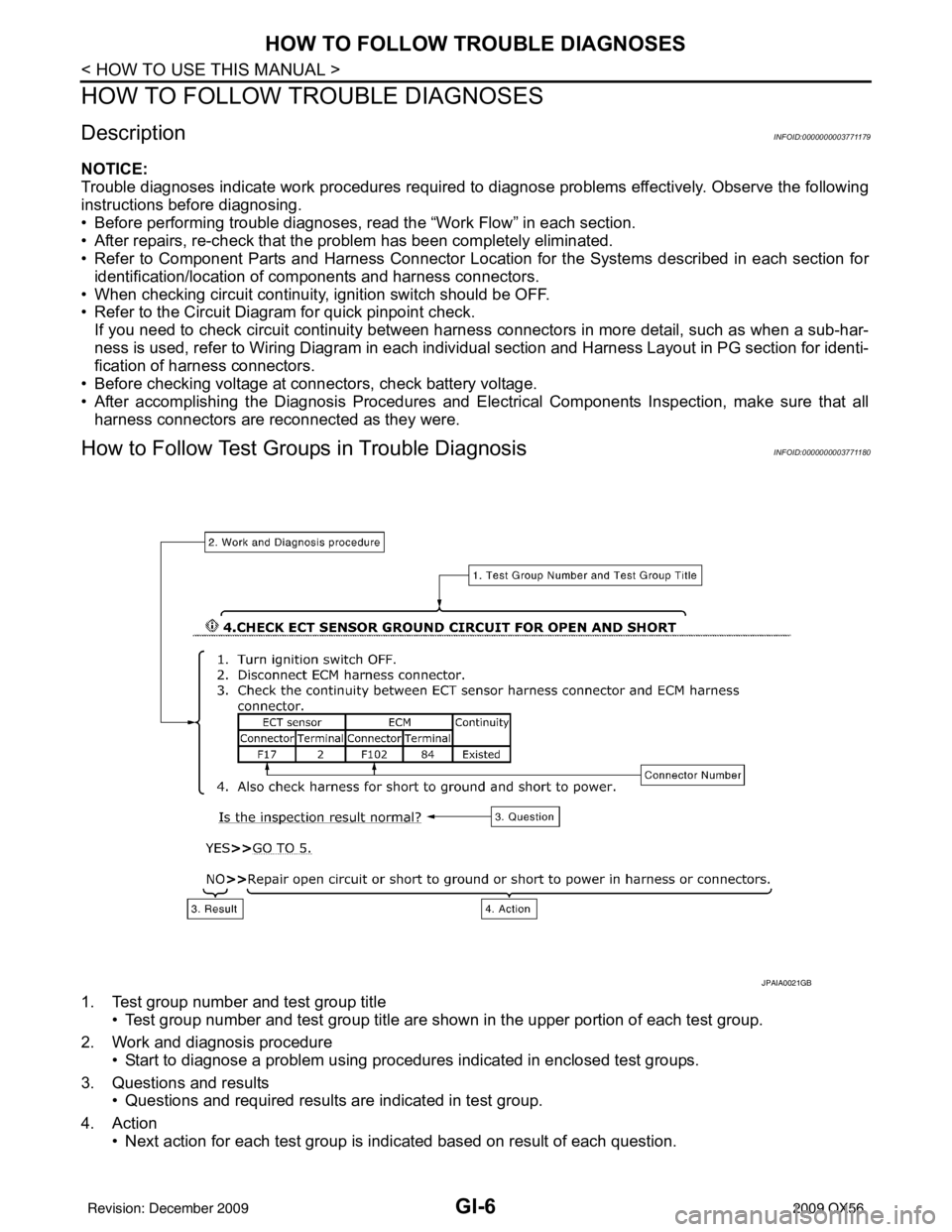
How to Follow Test Grou ps in Trouble DiagnosisINFOID:0000000003771180
1. Test group number and test group title
• Test group number and test group title are s hown in the upper portion of each test group.
2. Work and diagnosis procedure • Start to diagnose a problem using procedures indicated in enclosed test groups.
3. Questions and results • Questions and required results are indicated in test group.
4. Action • Next action for each test group is indicated based on result of each question.
JPAIA0021GB
Revision: December 20092009 QX56
Page 2220 of 4171
GI-26
< PRECAUTION >
PRECAUTIONS
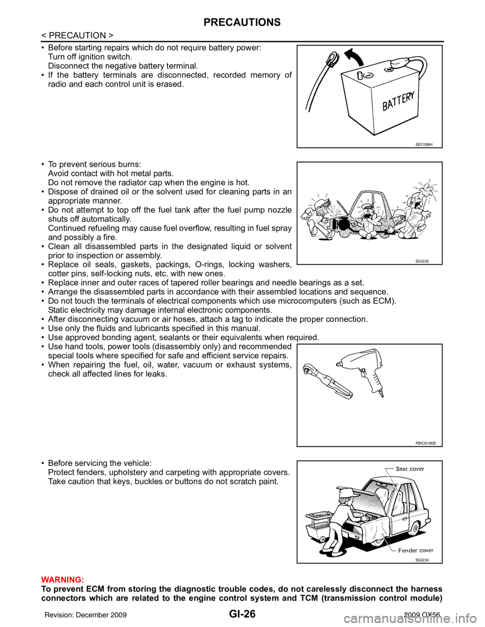
• Before starting repairs which do not require battery power:Turn off ignition switch.
Disconnect the negative battery terminal.
• If the battery terminals are disconnected, recorded memory of radio and each control unit is erased.
• To prevent serious burns: Avoid contact with hot metal parts.
Do not remove the radiator cap when the engine is hot.
• Dispose of drained oil or the solvent used for cleaning parts in an appropriate manner.
• Do not attempt to top off the fuel tank after the fuel pump nozzle
shuts off automatically.
Continued refueling may cause fuel overflow, resulting in fuel spray
and possibly a fire.
• Clean all disassembled parts in the designated liquid or solvent prior to inspection or assembly.
• Replace oil seals, gaskets, packings, O-rings, locking washers,
cotter pins, self-locking nuts, etc. with new ones.
• Replace inner and outer races of tapered roller bearings and needle bearings as a set.
• Arrange the disassembled parts in accordance with their assembled locations and sequence.
• Do not touch the terminals of electrical com ponents which use microcomputers (such as ECM).
Static electricity may damage internal electronic components.
• After disconnecting vacuum or air hoses, atta ch a tag to indicate the proper connection.
• Use only the fluids and lubricants specified in this manual.
• Use approved bonding agent, sealants or their equivalents when required.
• Use hand tools, power tools (disassembly only) and recommended special tools where specified for safe and efficient service repairs.
• When repairing the fuel, oil, water, vacuum or exhaust systems, check all affected lines for leaks.
• Before servicing the vehicle: Protect fenders, upholstery and carpeting with appropriate covers.
Take caution that keys, buckles or buttons do not scratch paint.
WARNING:
To prevent ECM from storing the diagnostic tro uble codes, do not carelessly disconnect the harness
connectors which are related to the engine control system and TCM (transmission control module)
SEF289H
SGI233
PBIC0190E
SGI234
Revision: December 20092009 QX56