Page 2072 of 4171

EXL-124
< ECU DIAGNOSIS >
IPDM E/R (INTELLIGENT POWER DISTRIBUTION MODULE ENGINE ROOM)
Te r m i n a lWire
color Signal name Signal
input/
output Measuring condition
Reference value(Approx.)
Igni-
tion
switch Operation or condition
1 B/Y Battery power supply Input OFF —Battery voltage
2 R Battery power supply Input OFF —Battery voltage
3 BR ECM relay Output —Ignition switch ON or START
Battery voltage
Ignition switch OFF or ACC 0V
4 W/L ECM relay Output —Ignition switch ON or START
Battery voltage
Ignition switch OFF or ACC 0V
6L Throttle control motor
relay Output —Ignition switch ON or START
Battery voltage
Ignition switch OFF or ACC 0V
7 W/B ECM relay control Input — Ignition switch ON or START
0V
Ignition switch OFF or ACC Battery voltage
8 R/B Fuse 54 Output —Ignition switch ON or START
Battery voltage
Ignition switch OFF or ACC 0V
10 G Fuse 45 Output ONDaytime light system active
0V
Daytime light system inactive Battery voltage
11 Y/B A/C compressor Output ON or
START A/C switch ON or defrost A/C
switch
Battery voltage
A/C switch OFF or defrost A/C
switch 0V
12 L/W Ignition switch sup-
plied power Input —OFF or ACC
0V
ON or START Battery voltage
13 B/Y Fuel pump relay Output — Ignition switch ON or START
Battery voltage
Ignition switch OFF or ACC 0V
14 Y/R Fuse 49 Output —Ignition switch ON or START
Battery voltage
Ignition switch OFF or ACC 0V
15 LG/B Fuse 50 (VDC) Output — Ignition switch ON or START
Battery voltage
Ignition switch OFF or ACC 0V
15 GR Fuse 50 (ABS) Output — Ignition switch ON or START
Battery voltage
Ignition switch OFF or ACC 0V
16 G Fuse 51 Output —Ignition switch ON or START
Battery voltage
Ignition switch OFF or ACC 0V
17 W Fuse 55 Output —Ignition switch ON or START
Battery voltage
Ignition switch OFF or ACC 0V
19 W/R Starter motor Output START—Battery voltage
21 BR Ignition switch sup-
plied power
Input —OFF or ACC
0V
START Battery voltage
22 G Battery power supply Output OFF —Battery voltage
23 GR/W Door mirror defogger
output signal Output —When rear defogger switch is
ON
Battery voltage
When raker defogger switch is
OFF 0V
Revision: December 20092009 QX56
Page 2074 of 4171

EXL-126
< ECU DIAGNOSIS >
IPDM E/R (INTELLIGENT POWER DISTRIBUTION MODULE ENGINE ROOM)
41 Y/B Hood switch Input —Hood closed OFF
0V
Hood open ON Battery voltage
42 GR Oil pressure switch Input — Engine running
Battery voltage
Engine stopped 0V
43 L/Y Wiper auto stop signal Input ON or
START Wiper switch OFF, LO, INT Battery voltage
44 BR Daytime light relay
control Input ONDaytime light system active
0V
Daytime light system inactive Battery voltage
45 G/W Horn relay control Input ON When door locks are operated
using keyfob or Intelligent Key
(OFF
→ ON)* Battery voltage
→ 0V
46 GR Fuel pump relay con-
trol
Input —Ignition switch ON or START
0V
Ignition switch OFF or ACC Battery voltage
47 O Throttle control motor
relay control
Input —Ignition switch ON or START
0V
Ignition switch OFF or ACC Battery voltage
48 B/R Starter relay (inhibit
switch) InputON or
START Selector lever in "P" or "N"
0V
Selector lever any other posi-
tion Battery voltage
49 R/L Trailer tow relay Output ON Lighting
switch must
be in the 1st
positionOFF
0V
ON Battery voltage
50 W/R Front fog lamp (LH) Output ON or
START Lighting
switch must
be in the 2nd
position
(LOW beam
is ON) and
the front fog
lamp switch OFF
0V
ON Battery voltage
51 W/R Front fog lamp (RH) Output ON or
START Lighting
switch must
be in the 2nd
position
(LOW beam
is ON) and
the front fog
lamp switch OFF
0V
ON Battery voltage
52 L LH low beam head-
lamp Output — Lighting switch in 2nd position Battery voltage
54 R/Y RH low beam head-
lamp Output — Lighting switch in 2nd position Battery voltage
55 G LH high beam head-
lamp Output —Lighting switch in 2nd position
and placed in HIGH or PASS
position Battery voltage
56 L/W RH high beam head-
lamp Output —Lighting switch in 2nd position
and placed in HIGH or PASS
position Battery voltage
57 R/L Parking, license, and
tail lamp
Output ONLighting
swi
t
ch 1st po-
sition OFF
0V
ON Battery voltage
Te r m i n a l
Wire
color Signal name Signal
input/
output Measuring condition
Reference value(Approx.)
Igni-
tion
switch Operation or condition
Revision: December 20092009 QX56
Page 2091 of 4171
ADJUSTMENT AND INSPECTIONEXL-143
< ON-VEHICLE REPAIR >
C
DE
F
G H
I
J
K
M A
B
EXL
N
O P
ON-VEHICLE REPAIR
ADJUSTMENT AND INSPECTION
HEADLAMP
HEADLAMP : Aiming AdjustmentINFOID:0000000003776220
NOTE:
• For details, refer to the regulations in your area.
• If vehicle front body has been repaired and /or the headlamp assembly has been replaced, check headlamp
aiming.
HEADLAMP AIMING
NOTE:
• Before performing aiming adjustment, check the following:
- Ensure all tires are inflated to correct pressure.
- Place vehicle and screen on level surface.
- Ensure there is no load in vehicle other than the driver (or equivalent weight placed in driver's position). Coolant and engine oil filled to correct level, and fuel tank full.
- Confirm spare tire, jack and tools are properly stowed.
- Aim each headlamp individually and ensure other headlamp beam pattern is blocked from screen.
- Use adjusting screw to perform aiming adjustment
WKIA1859E
Revision: December 20092009 QX56
Page 2093 of 4171
ADJUSTMENT AND INSPECTIONEXL-145
< ON-VEHICLE REPAIR >
C
DE
F
G H
I
J
K
M A
B
EXL
N
O P
• See that vehicle is unloaded (except for full levels of coolant, engine oil and fuel, and spare tire, jack, and tools). Have the driver
or equivalent weight placed in driver seat.
Adjust aiming in the vertical direction by turning the adjustment
screw.
NOTE:
Access adjustment screw from underneath front bumper. Turn screw
clockwise to raise pattern and c ounterclockwise to lower pattern.
1. Set the distance between the screen and the center of the fog lamp lens as shown.
2. Turn front fog lamps ON.
3. Adjust front fog lamps using adjusting screw so that the top edge of the high intensity zone is 200 mm (7.9 in) below the height of
the fog lamp centers as shown.
• When performing adjustment, if necessary, cover the head-lamps and opposite fog lamp.
SEL350X
MEL327G
MEL328GA
Revision: December 20092009 QX56
Page 2154 of 4171

FL-1
ENGINE
C
DE
F
G H
I
J
K L
M
SECTION FL
A
FL
N
O P
CONTENTS
FUEL SYSTEM
PRECAUTION ....... ........................................2
PRECAUTIONS .............................................. .....2
Precaution for Supplemental Restraint System
(SRS) "AIR BAG" and "SEAT BELT PRE-TEN-
SIONER" ............................................................. ......
2
Precaution Necessary for Steering Wheel Rota-
tion After Battery Disconnect ............................... ......
2
FUEL SYSTEM ....................................................4
General Precaution ............................................. ......4
PREPARATION ............................................5
PREPARATION .............................................. .....5
Special Service Tool ........................................... ......5
Commercial Service Tool ..........................................5
BASIC INSPECTION ....................................6
FUEL SYSTEM ............................................... .....6
Checking Fuel Line ............................................. ......6
REMOVAL AND INSTALLATION ................7
FUEL LEVEL SENSOR UNIT, FUEL FILTER
AND FUEL PUMP ASSEMBLY .........................
7
Removal and Installation ..................................... .....7
FUEL TANK ......................................................11
Removal and Installation ..................................... ....11
DISASSEMBLY AND ASSEMBLY ..............16
FUEL LEVEL SENSOR UNIT, FUEL FILTER
AND FUEL PUMP ASSEMBLY ........................
16
Disassembly and Assembly ................................. ....16
SERVICE DATA AND SPECIFICATIONS
(SDS) ............... .......................................... ...
17
SERVICE DATA AND SPECIFICATIONS
(SDS) .................................................................
17
Standard and Limit .............................................. ....17
Revision: December 20092009 QX56
Page 2157 of 4171

FL-4
< PRECAUTION >
FUEL SYSTEM
FUEL SYSTEM
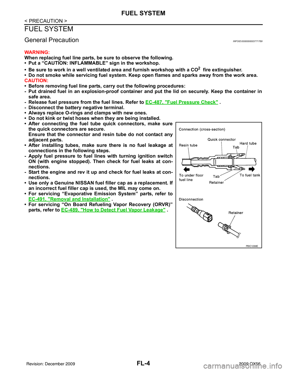
General PrecautionINFOID:0000000003771769
WARNING:
When replacing fuel line parts, be sure to observe the following.
• Put a “CAUTION: INFLAMMABLE” sign in the workshop.
• Be sure to work in a well ventilate d area and furnish workshop with a CO
2 fire extinguisher.
• Do not smoke while servicing fuel system. Keep open flames and sparks away from the work area.
CAUTION:
• Before removing fuel line parts, carry out the following procedures:
- Put drained fuel in an explosi on-proof container and put the lid on securely. Keep the container in
safe area.
- Release fuel pressure from the fuel lines. Refer to EC-487, "
Fuel Pressure Check" .
- Disconnect the battery negative terminal.
• Always replace O-rings and clamps with new ones.
• Do not kink or twist hoses when they are being installed.
• After connecting the fuel t ube quick connectors, make sure
the quick connectors are secure.
Ensure that the connector and resin tube do not contact any
adjacent parts.
• After installing tubes, make su re there is no fuel leakage at
connections in the following steps.
- Apply fuel pressure to fuel lines with turning ignition switch
ON (with engine stopped). Th en check for fuel leaks at con-
nections.
- Start the engine and rev it up and check for fuel leaks at con-
nections.
• Use only a Genuine NISSAN fuel filler cap as a replacement. If an incorrect fuel filler cap is used, the MIL may come on.
• For servicing “Evaporative Emission System” parts, refer to EC-491, "
Removal and Installation" .
• For servicing “On Board Refueling Vapor Recovery (ORVR)”
parts, refer to EC-489, "
How to Detect Fuel Vapor Leakage" .
PBIC1268E
Revision: December 20092009 QX56
Page 2158 of 4171
PREPARATIONFL-5
< PREPARATION >
C
DE
F
G H
I
J
K L
M A
FL
NP
O
PREPARATION
PREPARATION
Special Service ToolINFOID:0000000003771770
The actual shapes of the Kent-Moore
tools may differ from those of the special tools illustrated here.
Commercial Service ToolINFOID:0000000003771771
Tool number
(Kent-Moore No.)
Tool name Description
—
(J-46536)
Fuel tank lock ring tool Removing and installing fuel tank lock ring
LBIA0398E
Tool name
Description
Power tool Loosening bolts and nuts
PBIC0190E
Revision: December 20092009 QX56
Page 2159 of 4171
FL-6
< BASIC INSPECTION >
FUEL SYSTEM
BASIC INSPECTION
FUEL SYSTEM
Checking Fuel LineINFOID:0000000003771772
Inspect fuel lines, fuel filler cap and fuel tank for improper attach-
ment, leaks, cracks, damage, loose connections, chafing or deterio-
ration.
If necessary, repair or replace damaged parts.
SMA803A
Revision: December 20092009 QX56