Page 2792 of 4171

MWI-70
< ECU DIAGNOSIS >
BCM (BODY CONTROL MODULE)
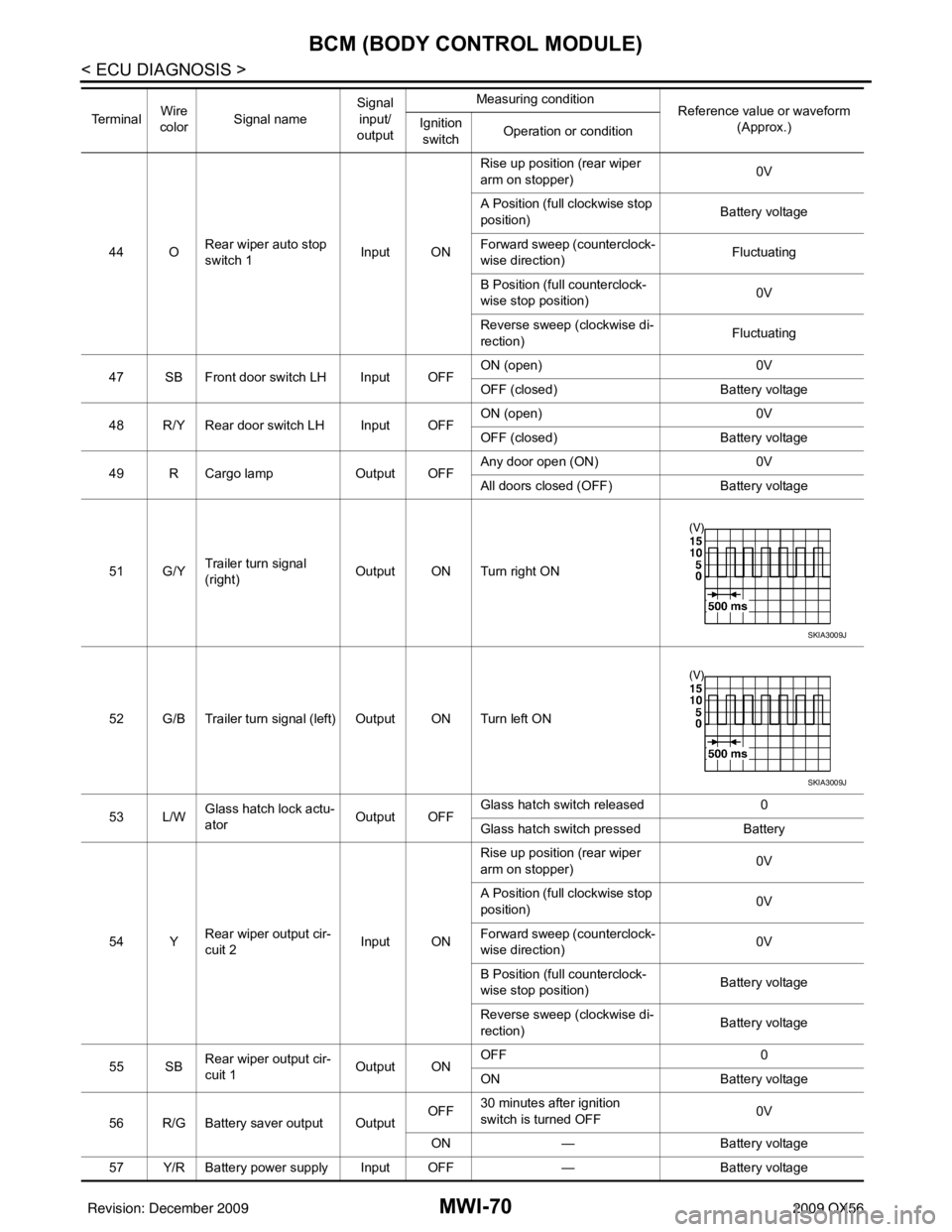
44 ORear wiper auto stop
switch 1 Input ONRise up position (rear wiper
arm on stopper)
0V
A Position (full clockwise stop
position) Battery voltage
Forward sweep (counterclock-
wise direction) Fluctuating
B Position (full counterclock-
wise stop position) 0V
Reverse sweep (clockwise di-
rection) Fluctuating
47 SB Front door switch LH Input OFF ON (open)
0V
OFF (closed) Battery voltage
48 R/Y Rear door switch LH Input OFF ON (open)
0V
OFF (closed) Battery voltage
49 R Cargo lamp Output OFFAny door open (ON)
0V
All doors closed (OFF) Battery voltage
51 G/Y Trailer turn signal
(right) Output ON Turn right ON
52 G/B Trailer turn signal (l eft) Output ON Turn left ON
53 L/W Glass hatch lock actu-
ator
Output OFFGlass hatch switch released
0
Glass hatch switch pressed Battery
54 Y Rear wiper output cir-
cuit 2 Input ONRise up position (rear wiper
arm on stopper)
0V
A Position (full clockwise stop
position) 0V
Forward sweep (counterclock-
wise direction) 0V
B Position (full counterclock-
wise stop position) Battery voltage
Reverse sweep (clockwise di-
rection) Battery voltage
55 SB Rear wiper output cir-
cuit 1 Output ONOFF
0
ON Battery voltage
56 R/G Battery saver output Output OFF
30 minutes after ignition
switch is turned OFF 0V
ON — Battery voltage
57 Y/R Battery power supply Input OFF —Battery voltage
Te r m i n a l
Wire
color Signal name Signal
input/
output Measuring condition
Reference value or waveform
(Approx.)
Ignition
switch Operation or condition
SKIA3009J
SKIA3009J
Revision: December 20092009 QX56
Page 2793 of 4171

MWI
BCM (BODY CONTROL MODULE)MWI-71
< ECU DIAGNOSIS >
C
DE
F
G H
I
J
K L
M B A
O P
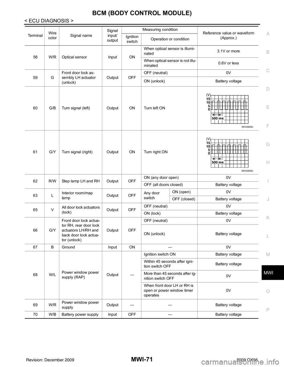
58 W/R Optical sensor Input ONWhen optical sensor is illumi-
nated
3.1V or more
When optical sensor is not illu-
minated 0.6V or less
59 G Front door lock as-
sembly LH actuator
(unlock) Output OFF
OFF (neutral)
0V
ON (unlock) Battery voltage
60 G/B Turn signal (left) Output ON Turn left ON
61 G/Y Turn signal (right) Output ON Turn right ON
62 R/W Step lamp LH and RH Output OFF ON (any door open)
0V
OFF (all doors closed) Battery voltage
63 L Interior room/map
lamp Output OFFAny door
switchON (open)
0V
OFF (closed) Battery voltage
65 V All door lock actuators
(lock) Output OFFOFF (neutral)
0V
ON (lock) Battery voltage
66 G/Y Front door lock actua-
tor RH, rear door lock
actuators LH/RH and
back door lock actua-
tor (unlock) Output OFF
OFF (neutral)
0V
ON (unlock) Battery voltage
67 B Ground Input ON—0V
68 W/L Power window power
supply (RAP) Output —Ignition switch ON
Battery voltage
Within 45 seconds after igni-
tion switch OFF Battery voltage
More than 45 seconds after ig-
nition switch OFF 0V
When front door LH or RH is
open or power window timer
operates 0V
69 W/R Power window power
supply
Output —
—Battery voltage
70 W/B Battery power supply Input OFF —Battery voltage
Te r m i n a l
Wire
color Signal name Signal
input/
output Measuring condition
Reference value or waveform
(Approx.)
Ignition
switch Operation or condition
SKIA3009J
SKIA3009J
Revision: December 20092009 QX56
Page 2802 of 4171
MWI-80
< ECU DIAGNOSIS >
IPDM E/R (INTELLIGENT POWER DISTRIBUTION MODULE ENGINE ROOM)
THFT HRN REQNot operated
OFF
• Panic alarm is activated
• Horn is activated with VEHICLE SECURITY (THEFT WARNING) SYS- TEM ON
HORN CHIRP Not operated
OFF
Door locking with Intelligent Key (horn chirp mode) ON
Monitor Item
ConditionValue/Status
Revision: December 20092009 QX56
Page 2806 of 4171

MWI-84
< ECU DIAGNOSIS >
IPDM E/R (INTELLIGENT POWER DISTRIBUTION MODULE ENGINE ROOM)
43 L/Y Wiper auto stop signal Input ON or
START Wiper switch OFF, LO, INT Battery voltage
44 BR Daytime light relay
control
(Canada only) Input ONDaytime light system active
0V
Daytime light system inactive Battery voltage
45 G/W Horn relay control Input ON When door locks are operated
using Intelligent Key (OFF
→
ON)* Battery voltage
→ 0V
46 GR Fuel pump relay con-
trol Input —Ignition switch ON or START
0V
Ignition switch OFF or ACC Battery voltage
47 O Throttle control motor
relay control Input —Ignition switch ON or START
0V
Ignition switch OFF or ACC Battery voltage
48 B/R Starter relay (inhibit
switch) Input
ON or
START Selector lever in "P" or "N"
0V
Selector lever any other posi-
tion Battery voltage
49 R/L Trailer tow relay
(With trailer tow)
Illumination
(Without trailer tow) Output ONLighting
switch must
be in the 1st
position OFF
0V
ON Battery voltage
50 W/R Front fog lamp (LH) Output ON or
START Lighting
switch must
be in the 2nd
position
(LOW beam
is ON) and
the front fog
lamp switch OFF
0V
ON Battery voltage
51 W/R Front fog lamp (RH) Output ON or
START Lighting
switch must
be in the 2nd
position
(LOW beam
is ON) and
the front fog
lamp switch OFF
0V
ON Battery voltage
52 L LH low beam head-
lamp
Output — Lighting switch in 2nd position Battery voltage
54 R/Y RH low beam head-
lamp Output — Lighting switch in 2nd position Battery voltage
55 G LH high beam head-
lamp Output —Lighting switch in 2nd position
and placed in HIGH or PASS
position Battery voltage
56 L/Y
(With
DTRL)
L/W
(Without DTRL) RH high beam head-
lamp
Output —Lighting switch in 2nd position
and placed in HIGH or PASS
position
Battery voltage
57 R/LPa
rking, license, and
tail lamp Output ONLighting
switch 1st po-
sition OFF
0V
ON Battery voltage
59 B Ground Input ——0V
Te r m i n a l
Wire
color Signal name Signal
input/
output Measuring condition
Reference value(Approx.)
Igni-
tion
switch Operation or condition
Revision: December 20092009 QX56
Page 2857 of 4171
PCS-20
< ECU DIAGNOSIS >[IPDM E/R]
IPDM E/R (INTELLIGENT POWER DI
STRIBUTION MODULE ENGINE ROOM)
THFT HRN REQNot operated
OFF
• Panic alarm is activated
• Horn is activated with VEHICLE SECURITY (THEFT WARNING) SYS- TEM ON
HORN CHIRP Not operated
OFF
Door locking with Intelligent Key (horn chirp mode) ON
Monitor Item
ConditionValue/Status
Revision: December 20092009 QX56
Page 2861 of 4171
![INFINITI QX56 2009 Factory Service Manual PCS-24
< ECU DIAGNOSIS >[IPDM E/R]
IPDM E/R (INTELLIGENT POWER DI
STRIBUTION MODULE ENGINE ROOM)
43 L/Y Wiper auto stop signal Input ON or
START Wiper switch OFF, LO, INT Battery voltage
44 BR Daytim INFINITI QX56 2009 Factory Service Manual PCS-24
< ECU DIAGNOSIS >[IPDM E/R]
IPDM E/R (INTELLIGENT POWER DI
STRIBUTION MODULE ENGINE ROOM)
43 L/Y Wiper auto stop signal Input ON or
START Wiper switch OFF, LO, INT Battery voltage
44 BR Daytim](/manual-img/42/57031/w960_57031-2860.png)
PCS-24
< ECU DIAGNOSIS >[IPDM E/R]
IPDM E/R (INTELLIGENT POWER DI
STRIBUTION MODULE ENGINE ROOM)
43 L/Y Wiper auto stop signal Input ON or
START Wiper switch OFF, LO, INT Battery voltage
44 BR Daytime light relay
control
(Canada only) Input ONDaytime light system active
0V
Daytime light system inactive Battery voltage
45 G/W Horn relay control Input ON When door locks are operated
using Intelligent Key (OFF
→
ON)* Battery voltage
→ 0V
46 GR Fuel pump relay con-
trol Input —Ignition switch ON or START
0V
Ignition switch OFF or ACC Battery voltage
47 O Throttle control motor
relay control Input —Ignition switch ON or START
0V
Ignition switch OFF or ACC Battery voltage
48 B/R Starter relay (inhibit
switch) Input
ON or
START Selector lever in "P" or "N"
0V
Selector lever any other posi-
tion Battery voltage
49 R/L Trailer tow relay
(With trailer tow)
Illumination
(Without trailer tow) Output ONLighting
switch must
be in the 1st
position OFF
0V
ON Battery voltage
50 W/R Front fog lamp (LH) Output ON or
START Lighting
switch must
be in the 2nd
position
(LOW beam
is ON) and
the front fog
lamp switch OFF
0V
ON Battery voltage
51 W/R Front fog lamp (RH) Output ON or
START Lighting
switch must
be in the 2nd
position
(LOW beam
is ON) and
the front fog
lamp switch OFF
0V
ON Battery voltage
52 L LH low beam head-
lamp
Output — Lighting switch in 2nd position Battery voltage
54 R/Y RH low beam head-
lamp Output — Lighting switch in 2nd position Battery voltage
55 G LH high beam head-
lamp Output —Lighting switch in 2nd position
and placed in HIGH or PASS
position Battery voltage
56 L/Y
(With
DTRL)
L/W
(Without DTRL) RH high beam head-
lamp
Output —Lighting switch in 2nd position
and placed in HIGH or PASS
position
Battery voltage
57 R/LPa
rking, license, and
tail lamp Output ONLighting
switch 1st po-
sition OFF
0V
ON Battery voltage
59 B Ground Input ——0V
Te r m i n a l
Wire
color Signal name Signal
input/
output Measuring condition
Reference value(Approx.)
Igni-
tion
switch Operation or condition
Revision: December 20092009 QX56
Page 2879 of 4171
PG-8
< BASIC INSPECTION >
INSPECTION AND ADJUSTMENT
INSPECTION AND ADJUSTMENT
ADDITIONAL SERVICE WHEN REMOVING BATTERY NEGATIVE TERMINAL
ADDITIONAL SERVICE WHEN REMOVING BATTERY NEGATIVE TERMINAL : Spe-
cial Repair Requirement
INFOID:0000000005864655
Required Procedure After Battery Disconnection
System ItemReference
Engine Control Idle Air Volume Learning Refer to EC-18
.
Brake Control Steering Angle Sensor Neutral Position Refer to BRC-8
.
Glasses, Window and Mirrors Power Window System Initialization Refer to TSB.
Body, Lock & Security Automatic Back Door Initialization Refer to DLK-9
.
Roof Sunroof Memory Reset/Initialization Refer to RF-5
.
Seats Automatic Drive Positioner System Initialization Refer to Owner's Manual.
Audio-Visual System Audio (Radio Preset)
Refer to Owner's Manual.
Navigation System Refer to Owner's Manual.
Rear View Monitor Guiding Line Adjustment Refer to AV- 7
.
Revision: December 20092009 QX56
Page 2912 of 4171

PG
HARNESSPG-41
< COMPONENT DIAGNOSIS >
C
DE
F
G H
I
J
K L
B A
O P
N
HARNESS
Harness LayoutINFOID:0000000003776571
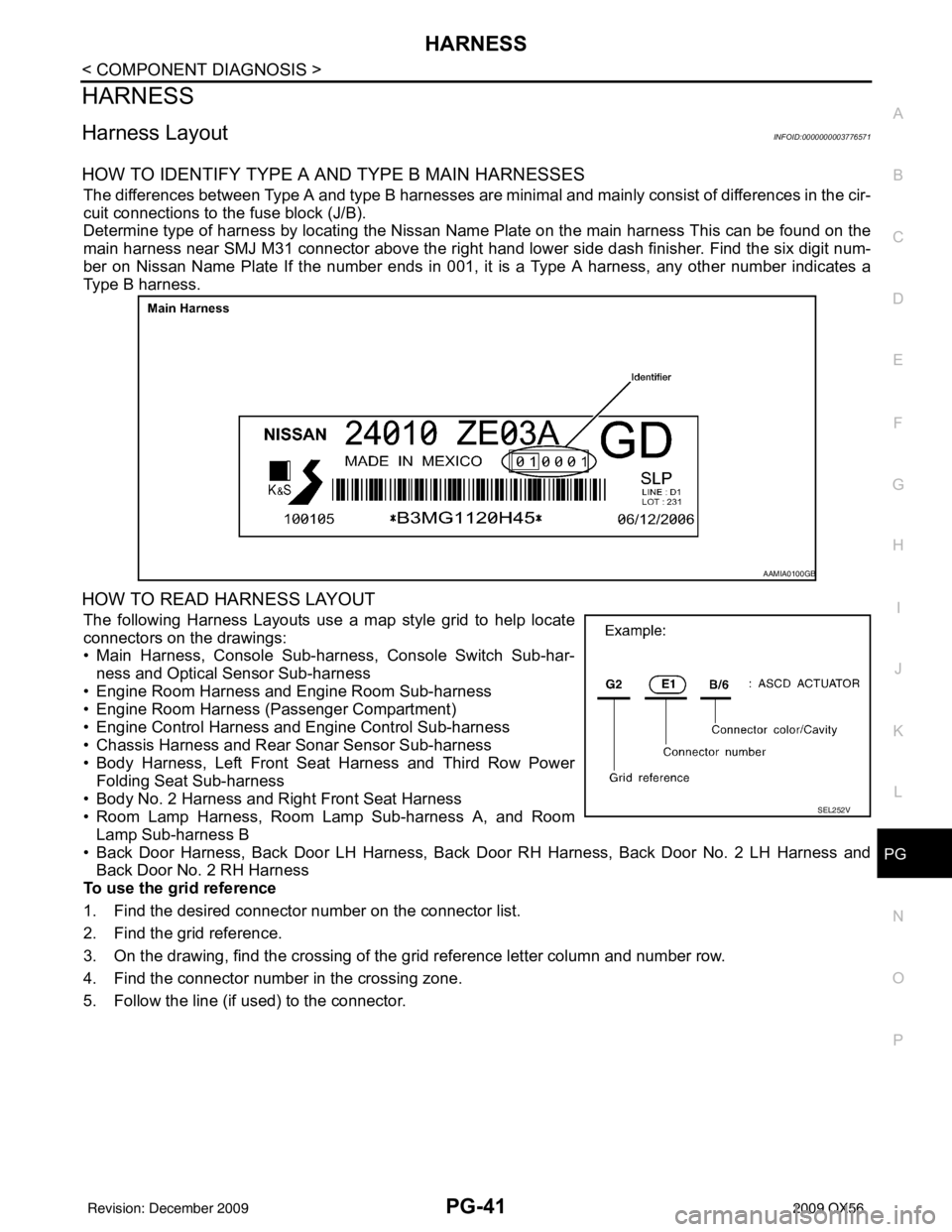
HOW TO IDENTIFY TYPE A AND TYPE B MAIN HARNESSES
The differences between Type A and type B harnesses are minimal and mainly consist of differences in the cir-
cuit connections to the fuse block (J/B).
Determine type of harness by locating the Nissan Name Plate on the main harness This can be found on the
main harness near SMJ M31 connector above the right hand
lower side dash finisher. Find the six digit num-
ber on Nissan Name Plate If the number ends in 001, it is a Type A harness, any other number indicates a
Type B harness.
HOW TO READ HARNESS LAYOUT
The following Harness Layouts use a map style grid to help locate
connectors on the drawings:
• Main Harness, Console Sub-harness, Console Switch Sub-har-
ness and Optical Sensor Sub-harness
• Engine Room Harness and Engine Room Sub-harness
• Engine Room Harness (Passenger Compartment)
• Engine Control Harness and Engine Control Sub-harness
• Chassis Harness and Rear Sonar Sensor Sub-harness
• Body Harness, Left Front Seat Harness and Third Row Power Folding Seat Sub-harness
• Body No. 2 Harness and Right Front Seat Harness
• Room Lamp Harness, Room Lamp Sub-harness A, and Room
Lamp Sub-harness B
• Back Door Harness, Back Door LH Harness, Back Door RH Harness, Back Door No. 2 LH Harness and
Back Door No. 2 RH Harness
To use the grid reference
1. Find the desired connector number on the connector list.
2. Find the grid reference.
3. On the drawing, find the crossing of the grid reference letter column and number row.
4. Find the connector number in the crossing zone.
5. Follow the line (if used) to the connector.
AAMIA0100GB
SEL252V
Revision: December 20092009 QX56