Page 2190 of 4171
FSU-20
< REMOVAL AND INSTALLATION >
KNUCKLE
7. Remove pinch bolt from steering knuckle using power tool, thenseparate lower link ball joint from steering knuckle.
8. Remove steering knuckle from vehicle.
INSPECTION AFTER REMOVAL
Check for deformity, cracks and damage on each part, replace if necessary.
• Perform ball joint inspection. Refer to FSU-10, "
Inspection".
INSTALLATION
Installation is in the reverse order of removal.
• Refer to FSU-13, "
Component" for tightening torques.
CAUTION:
Use a new cotter pin for installation of lock nut.
• When installing disc rotor on wheel hub and bearing assembly, align the marks.
NOTE:
When not using the alignment mark, refer to BR-7, "
DISC ROTOR
: Inspection".
• When installing wheel and tire, refer to WT-41, "
Adjustment".
LEIA0097E
WDIA0044E
Revision: December 20092009 QX56
Page 2194 of 4171

FSU-24
< SERVICE DATA AND SPECIFICATIONS (SDS)
SERVICE DATA AND SPECIFICATIONS (SDS)
*2: Target value 37° 31 ′ (37.52 °)
*3: Target value 33 ° 59 ′ (33.98 °)
*4: Target value 37 ° 44 ′ (37.73 °)
*5: Target value 33 ° 29 ′ (33.48 °)
*6 Some vehicles may not be equipped with straight (non-adjustable) lower link bolts and washers. In order to adjust camber and caster
on these vehicles, first replace the lower link bolts and washers with adjustable (cam) bolts and washers
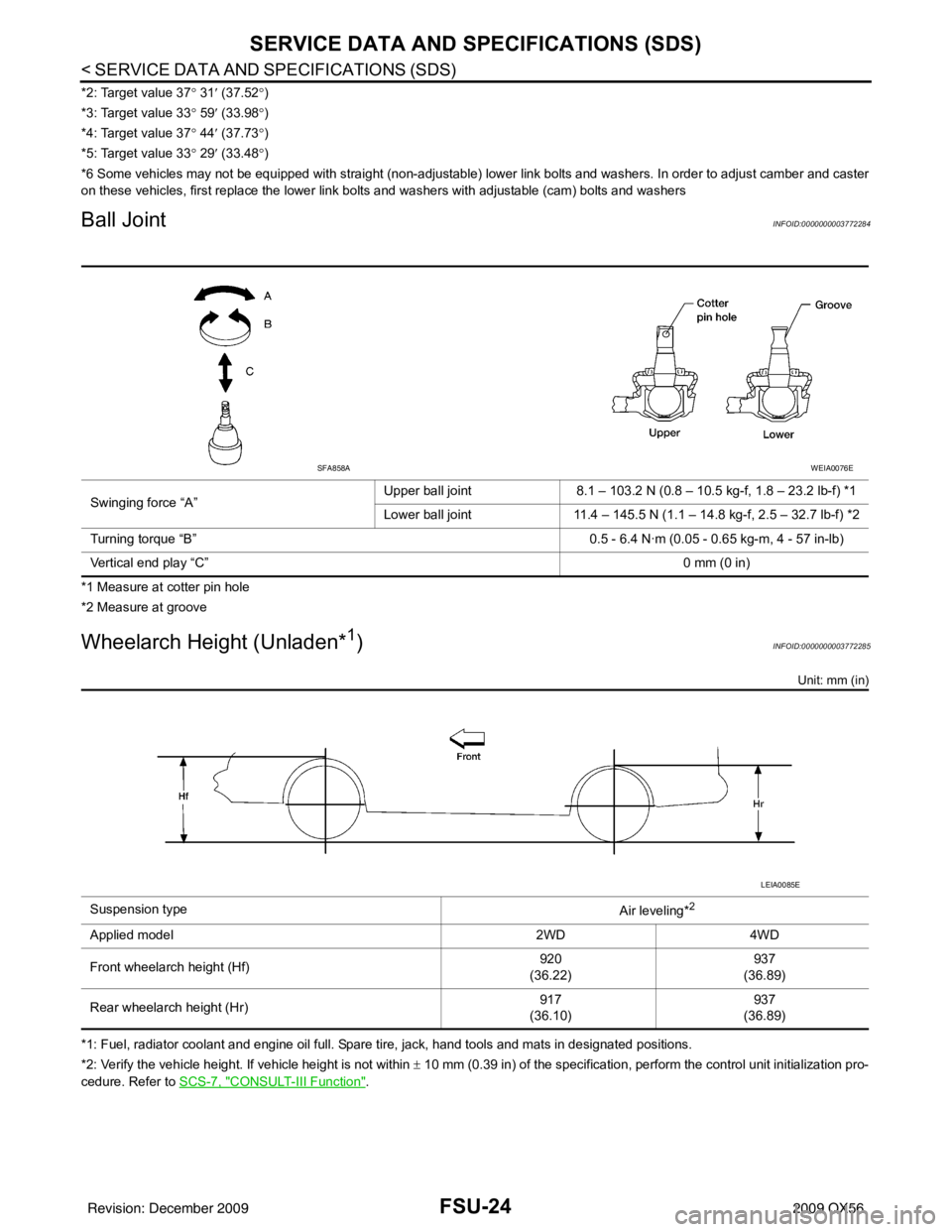
Ball JointINFOID:0000000003772284
*1 Measure at cotter pin hole
*2 Measure at groove
Wheelarch Height (Unladen*1)INFOID:0000000003772285
Unit: mm (in)
*1: Fuel, radiator coolant and engine oil full. Spare tire, jack, hand tools and mats in designated positions.
*2: Verify the vehicle height. If vehicle height is not within ± 10 mm (0.39 in) of the specification, perform the control unit initialization pro-
cedure. Refer to SCS-7, "
CONSULT-III Function".
Swinging force “A”
Upper ball joint
8.1 – 103.2 N (0.8 – 10.5 kg-f, 1.8 – 23.2 lb-f) *1
Lower ball joint 11.4 – 145.5 N (1.1 – 14.8 kg-f, 2.5 – 32.7 lb-f) *2
Turning torque “B” 0.5 - 6.4 N·m (0.05 - 0.65 kg-m, 4 - 57 in-lb)
Vertical end play “C” 0 mm (0 in)
SFA858AWEIA0076E
Suspension type
Air leveling*2
Applied model2WD4WD
Front wheelarch height (Hf) 920
(36.22) 937
(36.89)
Rear wheelarch height (Hr) 917
(36.10) 937
(36.89)
LEIA0085E
Revision: December 20092009 QX56
Page 2195 of 4171

GI-1
GENERAL INFORMATION
C
DE
F
G H
I
J
K L
M B
GI
SECTION GI
N
O P
CONTENTS
GENERAL INFORMATION
HOW TO USE THIS MANU AL ......................3
HOW TO USE THIS MANUAL ....................... .....3
Description .......................................................... ......3
Terms ........................................................................3
Units ..........................................................................3
Contents ....................................................................3
Relation between Illustrations and Descriptions .......4
Components ..............................................................4
HOW TO FOLLOW TROUBLE DIAGNOSES .....6
Description ................................................................6
How to Follow Test Groups in Trouble Diagnosis ......6
Key to Symbols Signifying Measurements or Pro-
cedures ............................................................... ......
7
HOW TO READ WIRING DIAGRAMS ................9
Connector symbols ............................................. ......9
Sample/wiring diagram -example- ...........................10
Description ..............................................................11
ABBREVIATIONS .......................................... ....13
Abbreviation List .................................................. ....13
TIGHTENING TORQUE OF STANDARD
BOLTS ................................................................
14
Tightening Torque Table .........................................14
RECOMMENDED CHEMICAL PRODUCTS
AND SEALANTS ............................................ ....
15
Recommended Chemical Products and Sealants ....15
TERMINOLOGY .................................................16
SAE J1930 Terminology List ............................... ....16
FEATURES OF NEW MODEL .....................20
IDENTIFICATION INFORMATION .....................20
Model Variation ................................................... ....20
Identification Number ..............................................21
Identification Plate ...................................................22
Dimensions .............................................................23
Wheels & Tires .................................................... ....23
PRECAUTION ..............................................24
PRECAUTIONS .................................................24
Description ........................................................... ....24
Precaution for Supplemental Restraint System
(SRS) "AIR BAG" and "SEAT BELT PRE-TEN-
SIONER" .................................................................
24
Precaution Necessary for Steering Wheel Rota-
tion After Battery Disconnect ...................................
24
Procedures without Cowl Top Cover .......................25
General Precautions ................................................25
Three Way Catalyst .................................................27
Precaution for Fuel (Unleaded Premium Gasoline
Recommended) .......................................................
27
Multiport Fuel Injection System or Engine Control
System .....................................................................
27
Hoses ......................................................................27
Engine Oils ..............................................................28
Air Conditioning .......................................................29
LIFTING POINT .................................................30
Pantograph Jack ......................................................30
Garage Jack and Safety Stand ................................30
2-Pole Lift ................................................................30
TOW TRUCK TOWING .....................................32
Tow Truck Towing ...................................................32
Vehicle Recovery (Freeing a stuck vehicle) ............33
BASIC INSPECTION ...................................34
SERVICE INFORMATION FOR ELECTRICAL
INCIDENT ..........................................................
34
Work Flow ............................................................ ....34
Control Units and Electrical Parts ............................34
How to Check Terminal ...........................................35
Intermittent Incident ............................................. ....38
Circuit Inspection .....................................................41
CONSULT-III CHECKING SYSTEM .................46
Revision: December 20092009 QX56
Page 3597 of 4171
ST-6
< PREPARATION >
PREPARATION
Commercial Service Tool
INFOID:0000000003775118
ST3127S000
(J-25765-A)
Preload gauge
1. GG9103000
(J-25765-A)
Torque wrench
2. HT62940000
(—)
Socket adapter
3. HT62900000
(—)
Socket adapter Inspecting sliding torque, steering torque and
rotating torque for ball joint
(—)
J-44372
Spring gauge Measure steering wheel turning force or rack
sliding force
Tool number
(Kent-Moore No.)
Tool name
Description
S-NT541
LST024
Tool name
Description
Power tool Removing nuts and bolts
PBIC0190E
Revision: December 20092009 QX56