Page 2752 of 4171
MWI-30
< COMPONENT DIAGNOSIS >
POWER SUPPLY AND GROUND CIRCUIT
POWER SUPPLY AND GROUND CIRCUIT
COMBINATION METER
COMBINATION METER : Diagnosis ProcedureINFOID:0000000003776633
1.CHECK FUSES
Check for blown combination meter fuses.
Is the inspection result normal?
YES >> GO TO 2
NO >> If fuse is blown, be sure to eliminate cause of malfunction before installing new fuse.
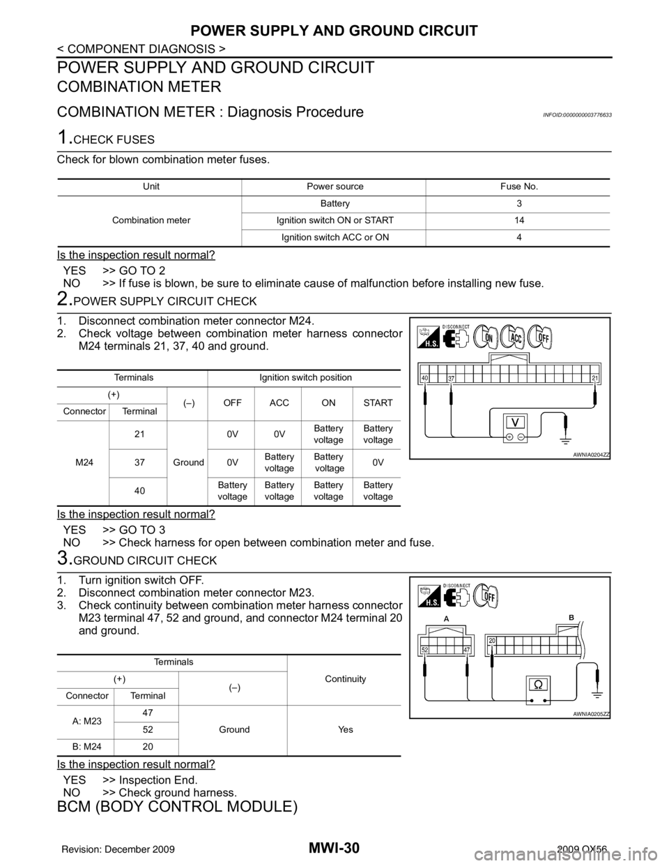
2.POWER SUPPLY CIRCUIT CHECK
1. Disconnect combination meter connector M24.
2. Check voltage between combination meter harness connector M24 terminals 21, 37, 40 and ground.
Is the inspection result normal?
YES >> GO TO 3
NO >> Check harness for open between combination meter and fuse.
3.GROUND CIRCUIT CHECK
1. Turn ignition switch OFF.
2. Disconnect combination meter connector M23.
3. Check continuity between combination meter harness connector M23 terminal 47, 52 and ground, and connector M24 terminal 20
and ground.
Is the inspection result normal?
YES >> Inspection End.
NO >> Check ground harness.
BCM (BODY CONTROL MODULE)
Unit Power source Fuse No.
Combination meter Battery 3
Ignition switch ON or START 14
Ignition switch ACC or ON 4
TerminalsIgnition switch position
(+) (–) OFF ACC ON START
Connector Terminal
M24 21
Ground 0V 0V
Battery
voltage Battery
voltage
37 0VBattery
voltage Battery
voltage 0V
40 Battery
voltage Battery
voltage Battery
voltage Battery
voltage
AWNIA0204ZZ
Te r m i n a l s
Continuity
(+)
(–)
Connector Terminal
A: M23 47
Ground Yes
52
B: M24 20
AWNIA0205ZZ
Revision: December 20092009 QX56
Page 2753 of 4171
MWI
POWER SUPPLY AND GROUND CIRCUITMWI-31
< COMPONENT DIAGNOSIS >
C
DE
F
G H
I
J
K L
M B A
O P
BCM (BODY CONTROL MODULE) : Diagnosis ProcedureINFOID:0000000004225393
1. CHECK FUSES AND FUSIBLE LINK
Check that the following fuses and fusible link are not blown.
Is the fuse blown?
YES >> Replace the blown fuse or fusible link after repairing the affected circuit.
NO >> GO TO 2
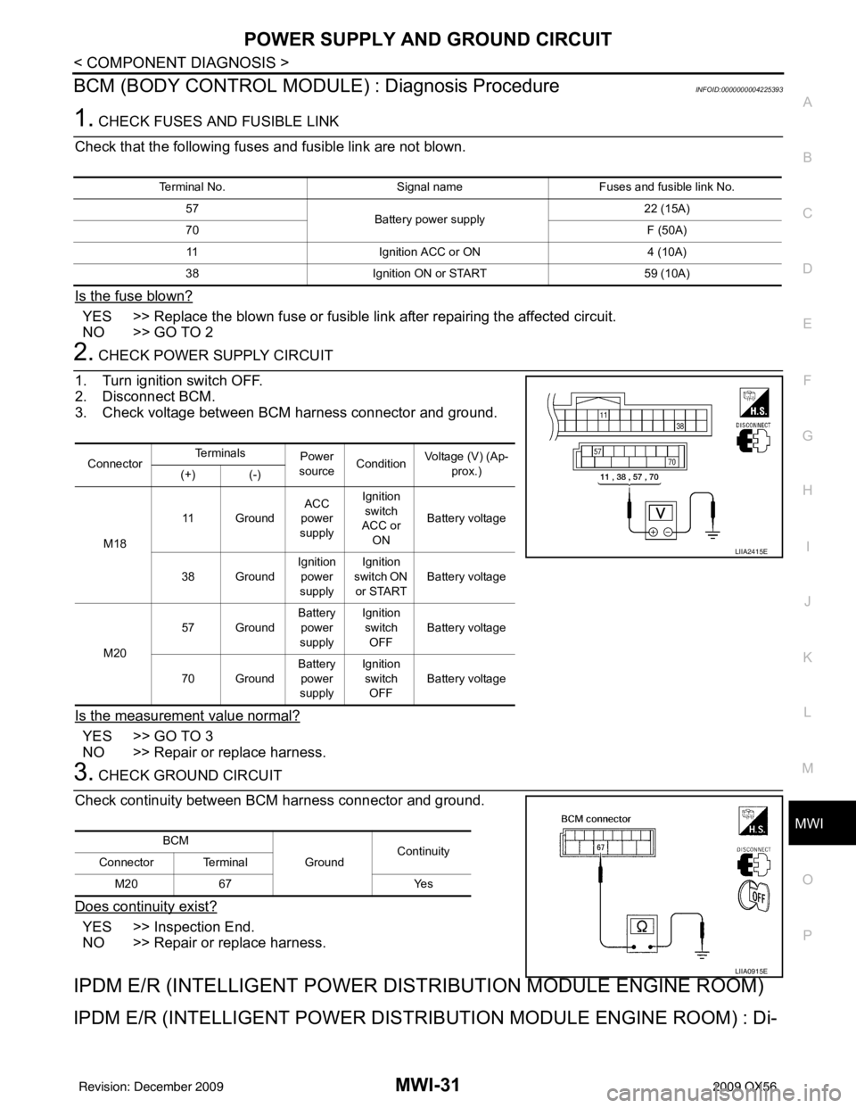
2. CHECK POWER SUPPLY CIRCUIT
1. Turn ignition switch OFF.
2. Disconnect BCM.
3. Check voltage between BCM harness connector and ground.
Is the measurement value normal?
YES >> GO TO 3
NO >> Repair or replace harness.
3. CHECK GROUND CIRCUIT
Check continuity between BCM harness connector and ground.
Does continuity exist?
YES >> Inspection End.
NO >> Repair or replace harness.
IPDM E/R (INTELLIGENT POWER DIST RIBUTION MODULE ENGINE ROOM)
IPDM E/R (INTELLIGENT POWER DISTRIBUTION MODULE ENGINE ROOM) : Di-
Terminal No. Signal nameFuses and fusible link No.
57 Battery power supply 22 (15A)
70 F (50A)
11 Ignition ACC or ON 4 (10A)
38 Ignition ON or START 59 (10A)
ConnectorTe r m i n a l s
Power
source Condition Voltage (V) (Ap-
prox.)
(+) (-)
M18 11 Ground
ACC
power
supply Ignition
switch
ACC or
ON Battery voltage
38 Ground Ignition
power
supply Ignition
switch ON or START Battery voltage
M20 57 Ground
Battery
power
supply Ignition
switch OFF Battery voltage
70 Ground Battery
power
supply Ignition
switch
OFF Battery voltage
LIIA2415E
BCM
GroundContinuity
Connector Terminal
M20 67 Yes
LIIA0915E
Revision: December 20092009 QX56
Page 2754 of 4171
MWI-32
< COMPONENT DIAGNOSIS >
POWER SUPPLY AND GROUND CIRCUIT
agnosis Procedure
INFOID:0000000004225394
1. CHECK FUSES AND FUSIBLE LINK
Check that the following IPDM E/R fuses or fusible link are not blown.
Is the fuse blown?
YES >> Replace the blown fuse or fusible link after repairing the affected circuit.
NO >> GO TO 2
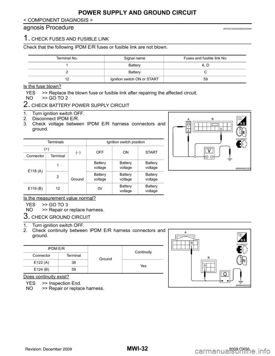
2. CHECK BATTERY POWER SUPPLY CIRCUIT
1. Turn ignition switch OFF.
2. Disconnect IPDM E/R.
3. Check voltage between IPDM E/R harness connectors and ground.
Is the measurement value normal?
YES >> GO TO 3
NO >> Repair or replace harness.
3. CHECK GROUND CIRCUIT
1. Turn ignition switch OFF.
2. Check continuity between IPDM E/R harness connectors and ground.
Does continuity exist?
YES >> Inspection End.
NO >> Repair or replace harness.
Terminal No. Signal nameFuses and fusible link No.
1 Battery A, D
2 Battery C
12 Ignition switch ON or START 59
TerminalsIgnition switch position
(+) (−) OFF ON START
Connector Terminal
E118 (A) 1
Ground Battery
voltage Battery
voltage Battery
voltage
2 Battery
voltage Battery
voltage Battery
voltage
E119 (B) 12 0VBattery
voltage Battery
voltage
AWMIA0023ZZ
IPDM E/R
GroundContinuity
Connector Terminal
E122 (A) 38
Ye s
E124 (B) 59
AWMIA0024ZZ
Revision: December 20092009 QX56
Page 2755 of 4171
MWI
FUEL LEVEL SENSOR SIGNAL CIRCUITMWI-33
< COMPONENT DIAGNOSIS >
C
DE
F
G H
I
J
K L
M B A
O P
FUEL LEVEL SENSOR SIGNAL CIRCUIT
DescriptionINFOID:0000000003776636
The fuel level sensor unit and fuel pump detects the approx imate fuel level in the fuel tank and transmits the
fuel level signal to the combination meter.
Component Function CheckINFOID:0000000003776637
1.COMBINATION METER INPUT SIGNAL
1. Select “METER/M&A” on CONSULT-III.
2. Using “FUEL METER” of “DATA MONITOR”, comp are the value of DATA MONITOR with fuel gauge
pointer of combination meter.
Does the data monitor value approximately match the fuel gauge indication?
YES >> Inspection End.
NO >> Replace combination meter. Refer to MWI-102, "
Removal and Installation".
Diagnosis ProcedureINFOID:0000000003776638
1.CHECK HARNESS CONNECTOR
1. Turn ignition switch OFF.
2. Check combination meter and fuel level sensor unit terminals (meter-side and harness-side) for poor con- nection.
Is the inspection result normal?
YES >> GO TO 2
NO >> Repair or replace terminals or connectors.
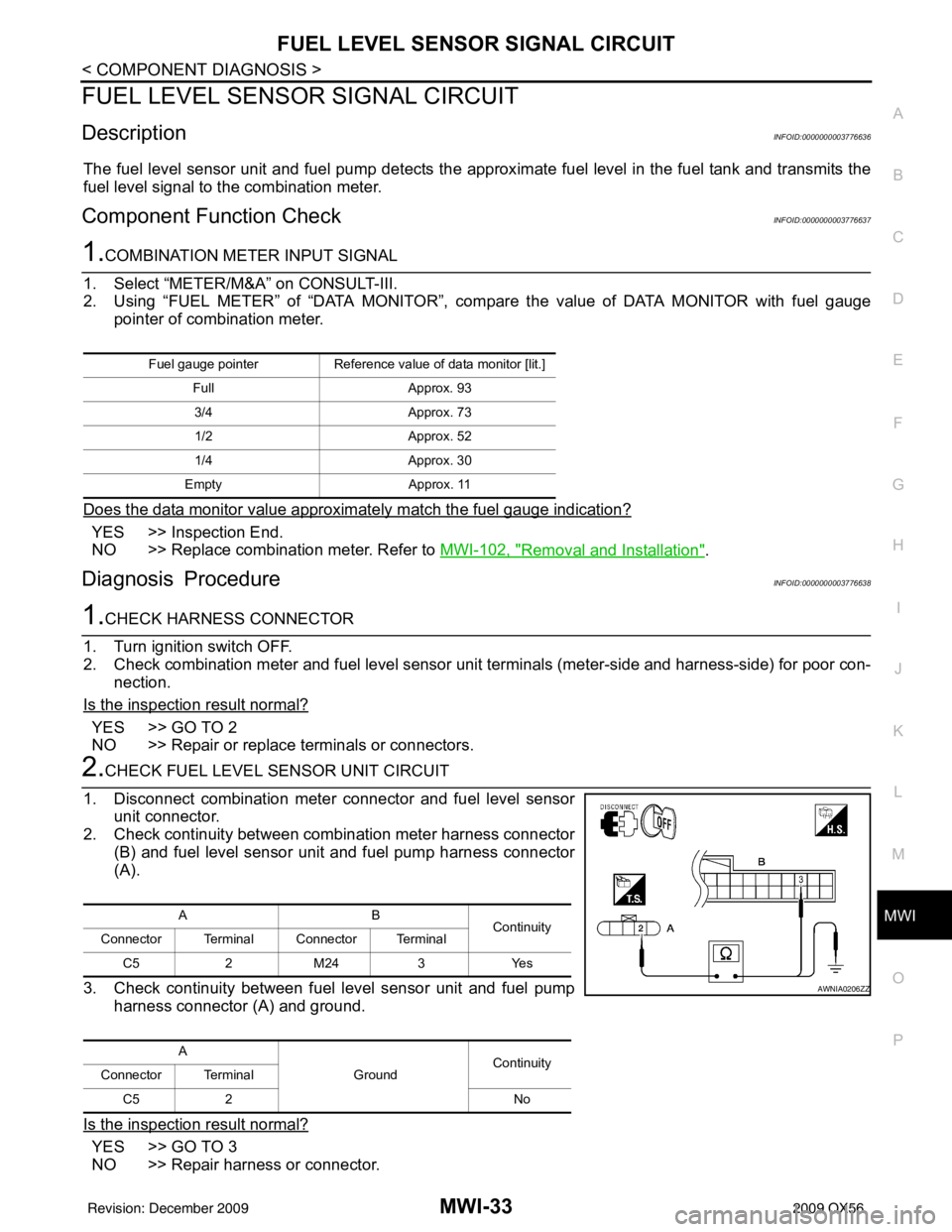
2.CHECK FUEL LEVEL SENSOR UNIT CIRCUIT
1. Disconnect combination meter connector and fuel level sensor unit connector.
2. Check continuity between combination meter harness connector
(B) and fuel level sensor unit and fuel pump harness connector
(A).
3. Check continuity between fuel level sensor unit and fuel pump harness connector (A) and ground.
Is the inspection result normal?
YES >> GO TO 3
NO >> Repair harness or connector.
Fuel gauge pointer Reference value of data monitor [lit.]
Full Approx. 93
3/4 Approx. 73
1/2 Approx. 52
1/4 Approx. 30
Empty Approx. 11
AB
Continuity
Connector Terminal Connector Terminal
C5 2 M24 3 Yes
A GroundContinuity
Connector Terminal
C5 2 No
AWNIA0206ZZ
Revision: December 20092009 QX56
Page 2757 of 4171
MWI
OIL PRESSURE SWITCH SIGNAL CIRCUIT
MWI-35
< COMPONENT DIAGNOSIS >
C
D E
F
G H
I
J
K L
M B A
O P
OIL PRESSURE SWITCH SIGNAL CIRCUIT
DescriptionINFOID:0000000003776640
Detects the engine oil pressure and transmits the oil pressure switch signal to the IPDM E/R.
Component Function CheckINFOID:0000000003776641
1.COMBINATION METER INPUT SIGNAL
1. Select “METER/M&A” on CONSULT-III.
2. Monitor “OIL W/L” of “DATA MONITOR” while operating ignition switch.
>> Inspection End.
Diagnosis ProcedureINFOID:0000000003776642
1.CHECK OIL PRESSURE SWITCH CIRCUIT
1. Turn ignition switch OFF.
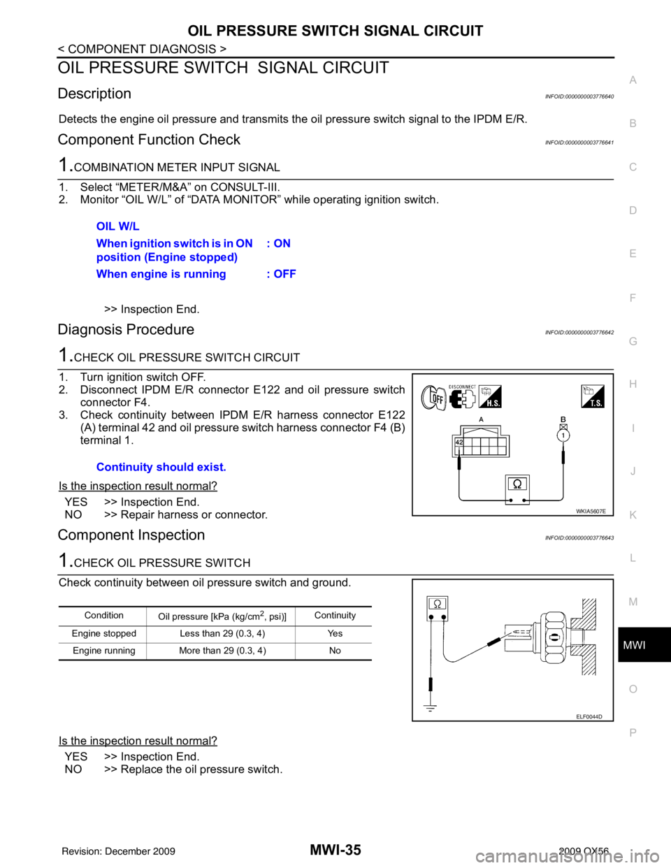
2. Disconnect IPDM E/R connector E122 and oil pressure switch
connector F4.
3. Check continuity between IPDM E/R harness connector E122
(A) terminal 42 and oil pressure switch harness connector F4 (B)
terminal 1.
Is the inspection result normal?
YES >> Inspection End.
NO >> Repair harness or connector.
Component InspectionINFOID:0000000003776643
1.CHECK OIL PRESSURE SWITCH
Check continuity between oil pressure switch and ground.
Is the inspection result normal?
YES >> Inspection End.
NO >> Replace the oil pressure switch. OIL W/L
When ignition switch is in ON
position (Engine stopped)
: ON
When engine is running : OFF
Continuity should exist.
WKIA5607E
Condition Oil pressure [kPa (kg/cm2, psi)]Continuity
Engine stopped Less than 29 (0.3, 4) Yes Engine running More than 29 (0.3, 4) No
ELF0044D
Revision: December 20092009 QX56
Page 2759 of 4171
MWI
WASHER LEVEL SWITCH SIGNAL CIRCUITMWI-37
< COMPONENT DIAGNOSIS >
C
DE
F
G H
I
J
K L
M B A
O P
WASHER LEVEL SWITCH SIGNAL CIRCUIT
DescriptionINFOID:0000000003776648
Transmits the washer level switch signal to the combination meter.
Diagnosis ProcedureINFOID:0000000003776649
1.CHECK WASHER FLUID LEVEL SWITCH SIGNAL CIRCUIT
1. Turn ignition switch OFF.
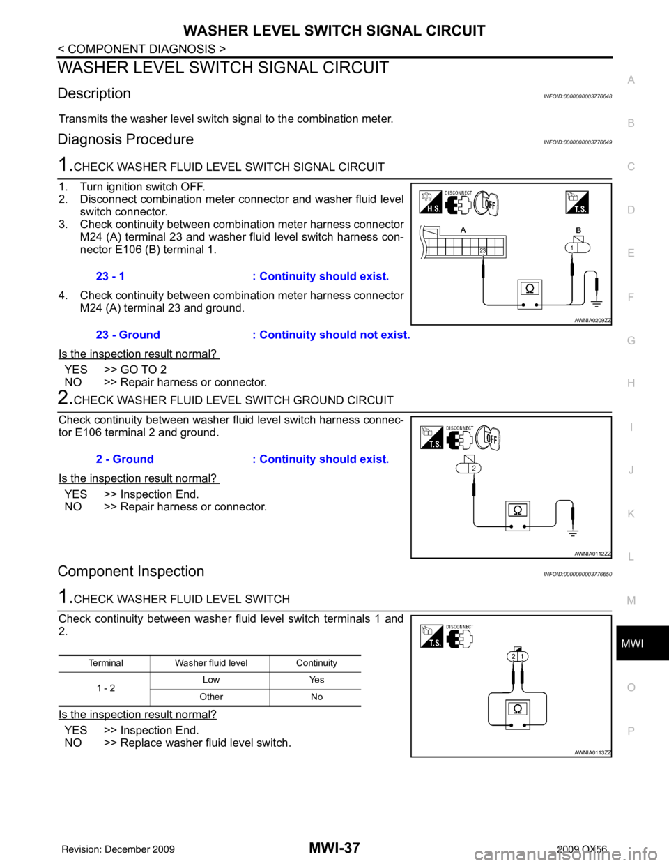
2. Disconnect combination meter connector and washer fluid level switch connector.
3. Check continuity between combination meter harness connector M24 (A) terminal 23 and washer fl uid level switch harness con-
nector E106 (B) terminal 1.
4. Check continuity between combination meter harness connector M24 (A) terminal 23 and ground.
Is the inspection result normal?
YES >> GO TO 2
NO >> Repair harness or connector.
2.CHECK WASHER FLUID LE VEL SWITCH GROUND CIRCUIT
Check continuity between washer fluid level switch harness connec-
tor E106 terminal 2 and ground.
Is the inspection result normal?
YES >> Inspection End.
NO >> Repair harness or connector.
Component InspectionINFOID:0000000003776650
1.CHECK WASHER FLUID LEVEL SWITCH
Check continuity between washer fluid level switch terminals 1 and
2.
Is the inspection result normal?
YES >> Inspection End.
NO >> Replace washer fluid level switch. 23 - 1
: Continuity should exist.
23 - Ground : Continuity should not exist.
AWNIA0209ZZ
2 - Ground: Continuity should exist.
AWNIA0112ZZ
TerminalWasher fluid level Continuity
1 - 2 Low
Yes
Other No
AWNIA0113ZZ
Revision: December 20092009 QX56
Page 2764 of 4171
MWI-42
< ECU DIAGNOSIS >
COMBINATION METER
ECU DIAGNOSIS
COMBINATION METER
Reference ValueINFOID:0000000003776653
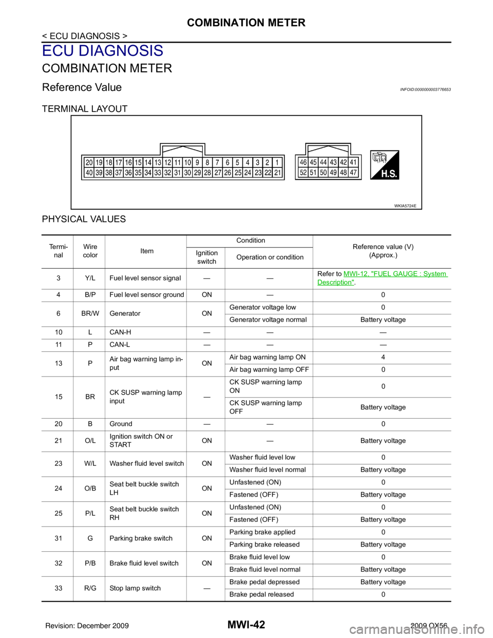
TERMINAL LAYOUT
PHYSICAL VALUES
WKIA5724E
Te r m i -nal Wire
color Item Condition
Reference value (V)
(Approx.)
Ignition
switch Operation or condition
3 Y/L Fuel level sensor signal — —Refer to MWI-12, "
FUEL GAUGE : System
Description".
4 B/P Fuel level sensor ground ON —0
6 BR/W Generator ONGenerator voltage low
0
Generator voltage normal Battery voltage
10 L CAN-H —— —
11 P C A N - L —— —
13 P Air bag warning lamp in-
put ONAir bag warning lamp ON
4
Air bag warning lamp OFF 0
15 BR CK SUSP warning lamp
input —CK SUSP warning lamp
ON
0
CK SUSP warning lamp
OFF Battery voltage
20 B Ground —— 0
21 O/L Ignition switch ON or
START ON
— Battery voltage
23 W/L Washer fluid level switch ON Washer fluid level low
0
Washer fluid level normal Battery voltage
24 O/B Seat belt buckle switch
LH ONUnfastened (ON)
0
Fastened (OFF) Battery voltage
25 P/L Seat belt buckle switch
RH ONUnfastened (ON)
0
Fastened (OFF) Battery voltage
31 G Parking brake switch ON Parking brake applied
0
Parking brake released Battery voltage
32 P/B Brake fluid level switch ON Brake fluid level low
0
Brake fluid level normal Battery voltage
33 R/G Stop lamp switch —Brake pedal depressed
Battery voltage
Brake pedal released 0
Revision: December 20092009 QX56
Page 2765 of 4171
MWI
COMBINATION METERMWI-43
< ECU DIAGNOSIS >
C
DE
F
G H
I
J
K L
M B A
O P
NOTE:
*1: With Type A main harness. For definition of Type A main harness, refer to PG-41, "
Harness Layout".
*2: With Type B main harness. For definition of Type B main harness, refer to PG-41, "
Harness Layout".
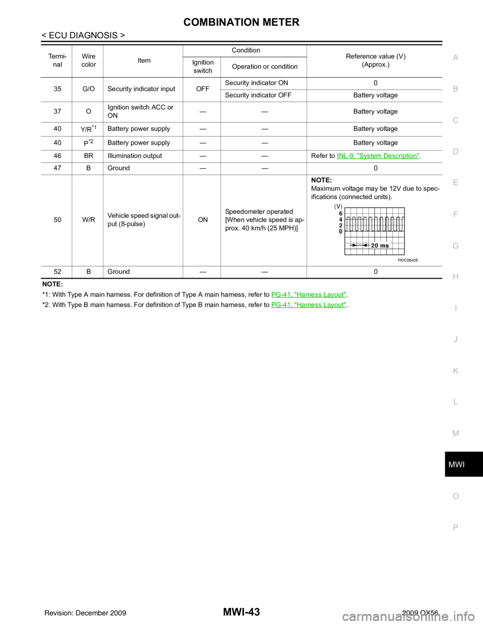
35 G/O Security indicator input OFF
Security indicator ON
0
Security indicator OFF Battery voltage
37 O Ignition switch ACC or
ON
—
— Battery voltage
40 Y/R
*1Battery power supply — —Battery voltage
40 P
*2Battery power supply — —Battery voltage
46 BR Illumination output ——Refer to INL-9, "
System Description".
47 B Ground —— 0
50 W/R Vehicle speed signal out-
put (8-pulse) ONSpeedometer operated
[When vehicle speed is ap-
prox. 40 km/h (25 MPH)] NOTE:
Maximum voltage may be 12V due to spec-
ifications (connected units).
52 B Ground —— 0
Te r m i -
nal Wire
color Item Condition
Reference value (V)
(Approx.)
Ignition
switch Operation or condition
PKIC0643E
Revision: December 20092009 QX56