2009 INFINITI QX56 crankshaf
[x] Cancel search: crankshafPage 2687 of 4171

MA-14
< ON-VEHICLE MAINTENANCE >
ENGINE MAINTENANCE
ENGINE MAINTENANCE
Checking Drive BeltsINFOID:0000000004215528
WARNING:
Be sure to perform when the engine is stopped.
1. Remove air duct and resonator assembly when inspecting drive belt.
2. Make sure that indicator (single line notch) of each auto tensioner is within the allowable working range“A” (between three line notches) as shown.
NOTE:
• Check the drive belt auto tensioner indication when the engine is cold.
• The indicator notch is located on the moving side of the drive belt auto tensioner.
3. Visually check entire belt for wear, damage or cracks.
4. If the indicator is out of allowable working range or belt is damaged, replace the belt. Refer to MA-14
.
DRIVE BELT TENSION
There is no manual drive belt tension adjustment. The driv e belt tension is automatically adjusted by the drive
belt auto tensioner.
Changing Engine CoolantINFOID:0000000004215534
WARNING:
• To avoid being scalded, never change the coolant when the engine is hot.
• Wrap a thick cloth around the cap to carefully remove the cap. First, turn the cap a quarter of a turn
to release any built-up pressure, th en push down and turn the cap all the way to remove it.
DRAINING ENGINE COOLANT
1. Turn ignition switch ON and set temperature control lever all the way to HOT position or the highest tem-
perature position. Wait 10 seconds and turn ignition switch OFF.
2. Remove the engine front undercover using power tool.
1. Drive belt 2. Power steering pump pulley 3. Generator pulley
4. Crankshaft pulley 5. A/C compressor6. Idler pulley
7. Cooling fan pulley 8. Water pump pulley 9. Drive belt auto tensioner
A. Allowable working range
LBIA0391E
Revision: December 20092009 QX56
Page 2922 of 4171

PG
HARNESSPG-51
< COMPONENT DIAGNOSIS >
C
DE
F
G H
I
J
K L
B A
O P
N
C3 F7 GR/3
: Ignition coil No. 4 (with power
transistor) F1 F60 GR/2 : Neutral-4LO switch
C3 F8 GR/3 : Ignition coil No. 6 (with power
transistor)
D5 F61 G/2: Intake valve timing control solenoid valve
(bank 1)
E2 F9 G/10 : A/T assembly D5 F62 B/3: Intake valve timing control position sensor
(bank 1)
C3 F10 — : Engine ground C4 F63 G/2: Intake valve timing control solenoid valve
(bank 2)
D3 F11 B/3 : Crankshaft position sensor (POS) C4 F64 B/3 : Intake valve timing control position sensor
(bank 2)
E1 F12 G/4 : Heated oxygen sensor 2 (bank2) E3 F65 GR/4 : Air fuel ratio (A/F) sensor 1 (bank1)
F2 F13 G/4 : Heated oxygen sensor 2 (bank1) C2 F68 GR/2 : Water valve
B2 F14 W/24 : To E5 Engine control sub-harness
D4 F15 GR/2 : EVAP canister purge volume control
solenoid valve C3 F101 B/6 : To F26
E5 F16 — : Engine ground C3 F102 B/2 : Knock sensor (bank 1)
C4 F18 GR/2 : Fuel injector No. 2 C3 F103 GR/2 : Engine coolant temperature sensor
D4 F20 GR/2 : Fuel injector No. 4 C3 F104 B/2 : Knock sensor (bank 2)
F4 F21 GR/2 : Condenser-1
D3 F22 GR/2 : Fuel injector No. 6
D4 F23 B/3 : Camshaft position sensor (phase)
D4 F26 B/6 : To F101
E3 F27 /1 : Starter motor
E3 F28 GR/1 : Starter motor
D4 F30 GR/2 : Fuel injector No. 1
D3 F31 GR/2 : Fuel injector No. 8
B2 F32 W/16 : To E2
C2 F33 W/16 : To E19
C2 F34 W/2 : To E39
B3 F39 /1 : Fusible link box (battery)
D4 F41 GR/2 : Fuel injector No. 3
D4 F42 GR/2 : Fuel injector No. 5
D3 F45 GR/2 : Fuel injector No. 7
B4 F46 B/3 : Power steering pressure sensor
E4 F47 GR/3 : Ignition coil No. 1 (with power
transistor)
E4 F48 GR/3 : Ignition coil No. 3 (with power
transistor)
E4 F49 GR/3 : Ignition coil No. 5 (with power
transistor)
D4 F50 W/6 : Electric throttle control actuator
E4 F51 GR/3 : Ignition coil No. 7 (with power
transistor)
D2 F52 GR/3 : Ignition coil No. 8 (with power
transistor)
E5 F53 B/6 : Mass air flow sensor
B2 F54 B/81 : ECM
F1 F55 B/2 : ATP switch
Revision: December 20092009 QX56
Page 3862 of 4171
TM-214
< REMOVAL AND INSTALLATION >
TRANSMISSION ASSEMBLY
REMOVAL AND INSTALLATION
TRANSMISSION ASSEMBLY
Removal and Installation (2WD)INFOID:0000000005892371
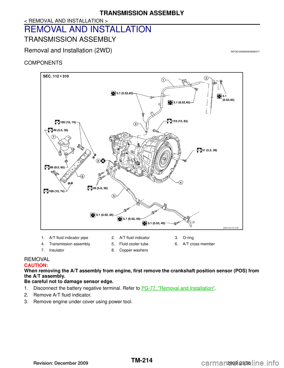
COMPONENTS
REMOVAL
CAUTION:
When removing the A/T assembly from engine, first remove the crankshaft position sensor (POS) from
the A/T assembly.
Be careful not to damage sensor edge.
1. Disconnect the battery negative terminal. Refer to PG-77, "Removal and Installation"
.
2. Remove A/T fluid indicator.
3. Remove engine under cover using power tool.
1. A/T fluid indicator pipe 2. A/T fluid indicator 3. O-ring
4. Transmission assembly 5. Fluid cooler tube 6. A/T cross member
7. Insulator 8. Copper washers
AWDIA0553GB
Revision: December 20092009 QX56
Page 3863 of 4171
TRANSMISSION ASSEMBLYTM-215
< REMOVAL AND INSTALLATION >
CEF
G H
I
J
K L
M A
B
TM
N
O P
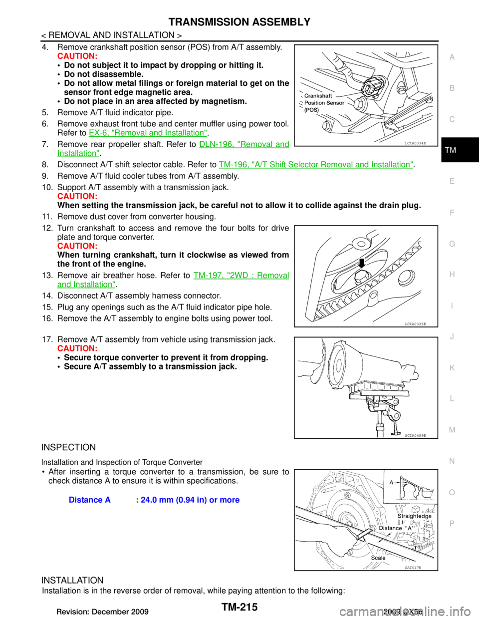
4. Remove crankshaft position sensor (POS) from A/T assembly. CAUTION:
Do not subject it to impact by dropping or hitting it.
Do not disassemble.
Do not allow metal filings or foreign material to get on the
sensor front edge magnetic area.
Do not place in an area affected by magnetism.
5. Remove A/T fluid indicator pipe.
6. Remove exhaust front tube and center muffler using power tool. Refer to EX-6, "Removal and Installation"
.
7. Remove rear propeller shaft. Refer to DLN-196, "Removal and
Installation".
8. Disconnect A/T shift selector cable. Refer to TM-196, "A/T Shift Selector Removal and Installation"
.
9. Remove A/T fluid cooler tubes from A/T assembly.
10. Support A/T assembly with a transmission jack. CAUTION:
When setting the transmission jack, be careful not to allow it to collide against the drain plug.
11. Remove dust cover from converter housing.
12. Turn crankshaft to access and remove the four bolts for drive plate and torque converter.
CAUTION:
When turning crankshaft, turn it clockwise as viewed from
the front of the engine.
13. Remove air breather hose. Refer to TM-197, "2WD : Removal
and Installation".
14. Disconnect A/T assembly harness connector.
15. Plug any openings such as the A/T fluid indicator pipe hole.
16. Remove the A/T assembly to engine bolts using power tool.
17. Remove A/T assembly from vehicle using transmission jack. CAUTION:
Secure torque converter to prevent it from dropping.
Secure A/T assembly to a transmission jack.
INSPECTION
Installation and Inspection of Torque Converter
After inserting a torque converter to a transmission, be sure to check distance A to ensure it is within specifications.
INSTALLATION
Installation is in the reverse order of removal, while paying attention to the following:
LCIA0334E
LCIA0335E
SCIA0499E
Distance A : 24.0 mm (0.94 in) or more
SAT017B
Revision: December 20092009 QX56
Page 3864 of 4171
TM-216
< REMOVAL AND INSTALLATION >
TRANSMISSION ASSEMBLY
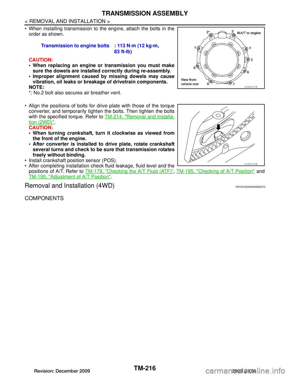
When installing transmission to the engine, attach the bolts in theorder as shown.
CAUTION:
When replacing an engine or transmission you must make
sure the dowels are installe d correctly during re-assembly.
Improper alignment caused by missing dowels may cause
vibration, oil leaks or breakage of drivetrain components.
NOTE:
*: No.2 bolt also secures air breather vent.
Align the positions of bolts for drive plate with those of the torque converter, and temporarily tight en the bolts. Then tighten the bolts
with the specified torque. Refer to TM-214, "Removal and Installa-
tion (2WD)".
CAUTION:
When turning crankshaft, turn it clockwise as viewed from
the front of the engine.
After converter is installed to drive plate, rotate crankshaft several turns and check to be su re that transmission rotates
freely without binding.
Install crankshaft position sensor (POS).
After completing installation check fluid leakage, fluid level and the positions of A/T. Refer to TM-179, "Checking the A/T Fluid (ATF)"
, TM-195, "Checking of A/T Position" and
TM-195, "Adjustment of A/T Position"
.
Removal and Installation (4WD)INFOID:0000000005892372
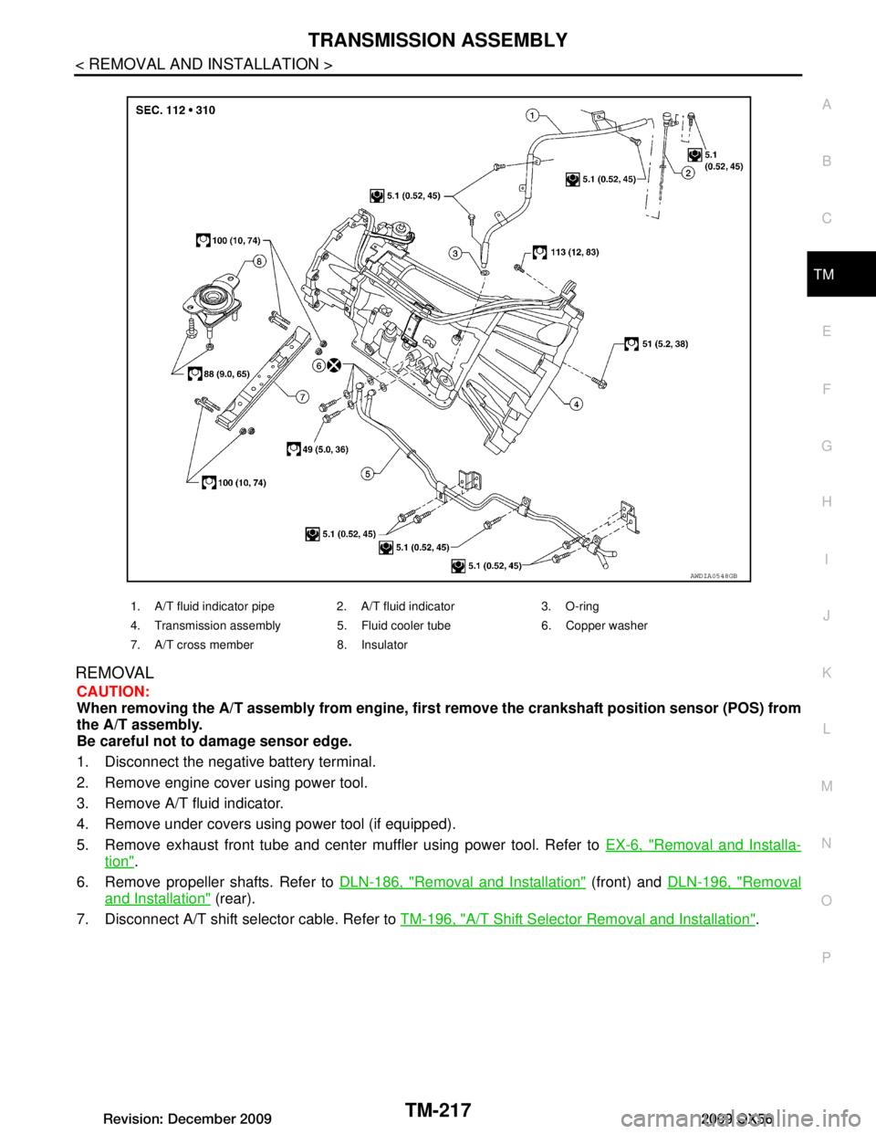
COMPONENTS
Transmission to engine bolts : 113 N·m (12 kg-m,
83 ft-lb)
LCIA0371E
LCIA0335E
Revision: December 20092009 QX56
Page 3865 of 4171
TRANSMISSION ASSEMBLYTM-217
< REMOVAL AND INSTALLATION >
CEF
G H
I
J
K L
M A
B
TM
N
O P
REMOVAL
CAUTION:
When removing the A/T assembly from engine, firs t remove the crankshaft position sensor (POS) from
the A/T assembly.
Be careful not to damage sensor edge.
1. Disconnect the negative battery terminal.
2. Remove engine cover using power tool.
3. Remove A/T fluid indicator.
4. Remove under covers using power tool (if equipped).
5. Remove exhaust front tube and center muffler using power tool. Refer to EX-6, "Removal and Installa-
tion".
6. Remove propeller shafts. Refer to DLN-186, "Removal and Installation"
(front) and DLN-196, "Removal
and Installation" (rear).
7. Disconnect A/T shift selector cable. Refer to TM-196, "A/T Shift Selector Removal and Installation"
.
1. A/T fluid indicator pipe 2. A/T fluid indicator 3. O-ring
4. Transmission assembly 5. Fluid cooler tube 6. Copper washer
7. A/T cross member 8. Insulator
AWDIA0548GB
Revision: December 20092009 QX56
Page 3866 of 4171
TM-218
< REMOVAL AND INSTALLATION >
TRANSMISSION ASSEMBLY
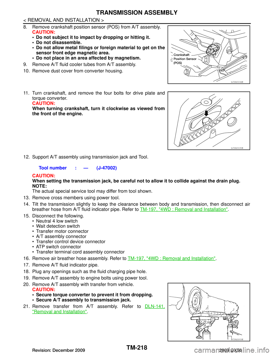
8. Remove crankshaft position sensor (POS) from A/T assembly.CAUTION:
Do not subject it to impact by dropping or hitting it.
Do not disassemble.
Do not allow metal filings or fo reign material to get on the
sensor front edge magnetic area.
Do not place in an area affected by magnetism.
9. Remove A/T fluid cooler tubes from A/T assembly.
10. Remove dust cover from converter housing.
11. Turn crankshaft, and remove the four bolts for drive plate and torque converter.
CAUTION:
When turning crankshaft, turn it clockwise as viewed from
the front of the engine.
12. Support A/T assembly using transmission jack and Tool. CAUTION:
When setting the transmission jack, be careful not to allow it to collide against the drain plug.
NOTE:
The actual special service tool may differ from tool shown.
13. Remove cross members using power tool.
14. Tilt the transmission slightly to keep the cl earance between body and transmission, then disconnect air
breather hose from A/T fluid indicator pipe. Refer to TM-197, "4WD : Removal and Installation"
.
15. Disconnect the following. Neutral 4 low switch
Wait detection switch
Transfer motor connector
A/T assembly connector
Transfer control device connector
ATP switch connector
Transfer terminal cord assembly connector
16. Remove air breather hose assembly. Refer to TM-197, "4WD : Removal and Installation"
.
17. Remove A/T fluid indicator pipe.
18. Plug any openings such as the fluid charging pipe hole.
19. Remove A/T assembly to engine bolts using power tool.
20. Remove A/T assembly with transfer from vehicle. CAUTION:
Secure torque converter to prevent it from dropping.
Secure A/T assembly to transmission jack.
21. Remove transfer from A/T assembly. Refer to DLN-141,
"Removal and Installation".
LCIA0334E
LCIA0335E
Tool number : — (J-47002)
SCIA2203E
Revision: December 20092009 QX56
Page 3867 of 4171
TRANSMISSION ASSEMBLYTM-219
< REMOVAL AND INSTALLATION >
CEF
G H
I
J
K L
M A
B
TM
N
O P
INSPECTION
Installation and Inspection of Torque Converter
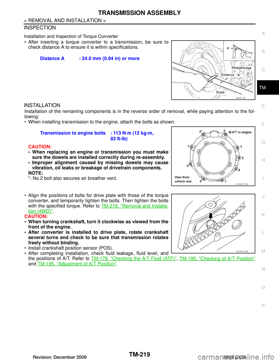
After inserting a torque converter to a transmission, be sure to check distance A to ensure it is within specifications.
INSTALLATION
Installation of the remaining components is in the revers e order of removal, while paying attention to the fol-
lowing:
When installing transmission to the engine, attach the bolts as shown.
CAUTION:
When replacing an engine or transmission you must make sure the dowels are installed correctly during re-assembly.
Improper alignment caused by missing dowels may cause vibration, oil leaks or breakage of drivetrain components.
NOTE:
*: No.2 bolt also secures air breather vent.
Align the positions of bolts for dr ive plate with those of the torque
converter, and temporarily tighten the bolts. Then tighten the bolts
with the specified torque. Refer to TM-216, "Removal and Installa-
tion (4WD)".
CAUTION:
When turning crankshaft, turn it clockwise as viewed from the
front of the engine.
After converter is installed to drive plate, rotate crankshaft
several turns and check to be sure that transmission rotates
freely without binding.
Install crankshaft position sensor (POS).
After completing installation, check fluid leakage, fluid level, and the positions of A/T. Refer to TM-179, "Checking the A/T Fluid (ATF)"
, TM-195, "Checking of A/T Position"
and TM-195, "Adjustment of A/T Position".
Distance A : 24.0 mm (0.94 in) or more
SAT017B
Transmission to engine bolts : 113 N·m (12 kg-m,
83 ft-lb)
LCIA0371E
LCIA0335E
Revision: December 20092009 QX56