Page 2464 of 4171

INL-20
< COMPONENT DIAGNOSIS >
STEP LAMP CIRCUIT
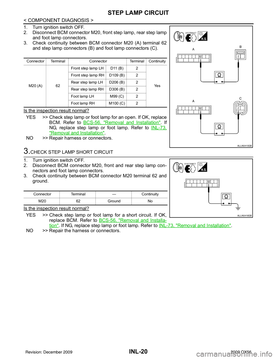
1. Turn ignition switch OFF.
2. Disconnect BCM connector M20, front step lamp, rear step lampand foot lamp connectors.
3. Check continuity between BCM connector M20 (A) terminal 62 and step lamp connectors (B) and foot lamp connectors (C).
Is the inspection result normal?
YES >> Check step lamp or foot lamp for an open. If OK, replace BCM. Refer to BCS-56, "
Removal and Installation". If
NG, replace step lamp or foot lamp. Refer to INL-73,
"Removal and Installation".
NO >> Repair harness or connectors.
3.CHECK STEP LAMP SHORT CIRCUIT
1. Turn ignition switch OFF.
2. Disconnect BCM connector M20, front and rear step lamp con- nectors and foot lamp connectors.
3. Check continuity between BCM connector M20 terminal 62 and ground.
Is the inspection result normal?
YES >> Check step lamp or foot lamp for a short circuit. If OK, replace BCM. Refer to BCS-56, "
Removal and Installa-
tion". If NG, replace step lamp or foot lamp. Refer to INL-73, "Removal and Installation".
NO >> Repair the harness or connectors.
Connector Terminal ConnectorTerminal Continuity
M20 (A) 62 Front step lamp LH D11 (B) 2
Ye s
Front step lamp RH D109 (B) 2
Rear step lamp LH D206 (B) 2
Rear step lamp
RH D306 (B) 2
Foot lamp LH M99 (C) 2
Foot lamp RH M100 (C) 2
ALLIA0415GB
Connector Terminal —Continuity
M20 62Ground No
ALLIA0416GB
Revision: December 20092009 QX56
Page 2465 of 4171

CARGO LAMP CONTROL CIRCUITINL-21
< COMPONENT DIAGNOSIS >
C
DE
F
G H
I
J
K
M A
B
INL
N
O P
CARGO LAMP CONTROL CIRCUIT
DescriptionINFOID:0000000003776260
Controls the cargo lamp (ground side) to turn the cargo lamp ON and OFF.
Component Function CheckINFOID:0000000003776261
CAUTION:
Before performing the diagnosis, check that the following is normal.
• Battery saver output/power supply
• Cargo lamp bulb
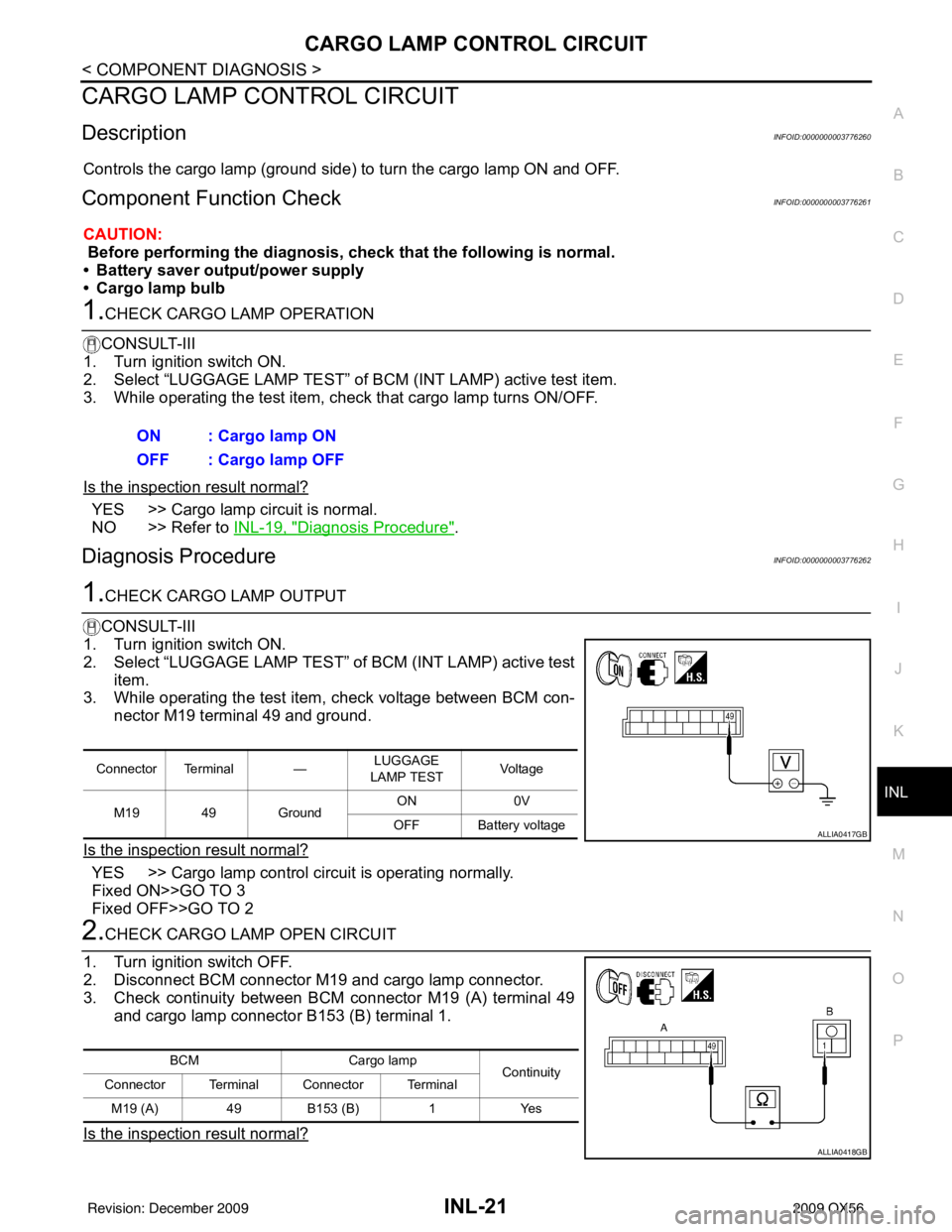
1.CHECK CARGO LAMP OPERATION
CONSULT-III
1. Turn ignition switch ON.
2. Select “LUGGAGE LAMP TEST” of BCM (INT LAMP) active test item.
3. While operating the test item, chec k that cargo lamp turns ON/OFF.
Is the inspection result normal?
YES >> Cargo lamp circuit is normal.
NO >> Refer to INL-19, "
Diagnosis Procedure".
Diagnosis ProcedureINFOID:0000000003776262
1.CHECK CARGO LAMP OUTPUT
CONSULT-III
1. Turn ignition switch ON.
2. Select “LUGGAGE LAMP TEST” of BCM (INT LAMP) active test
item.
3. While operating the test item, check voltage between BCM con-
nector M19 terminal 49 and ground.
Is the inspection result normal?
YES >> Cargo lamp control circuit is operating normally.
Fixed ON>>GO TO 3
Fixed OFF>>GO TO 2
2.CHECK CARGO LAMP OPEN CIRCUIT
1. Turn ignition switch OFF.
2. Disconnect BCM connector M19 and cargo lamp connector.
3. Check continuity between BCM connector M19 (A) terminal 49 and cargo lamp connector B153 (B) terminal 1.
Is the inspection result normal?
ON : Cargo lamp ON
OFF : Cargo lamp OFF
Connector Terminal — LUGGAGE
LAMP TEST Vo l ta g e
M19 49 Ground ON
0V
OFF Battery voltage
ALLIA0417GB
BCM Cargo lamp
Continuity
Connector Terminal Connector Terminal
M19 (A) 49B153 (B) 1Yes
ALLIA0418GB
Revision: December 20092009 QX56
Page 2466 of 4171
INL-22
< COMPONENT DIAGNOSIS >
CARGO LAMP CONTROL CIRCUIT
YES >> Check cargo lamp for an open. If OK, replace BCM. Refer to BCS-56, "Removal and Installation".
If NG, replace cargo lamp. Refer to INL-77, "
Removal and Installation".
NO >> Repair harness or connectors.
3.CHECK CARGO LAMP SHORT CIRCUIT
1. Turn ignition switch OFF.
2. Disconnect BCM connector M19 and cargo lamp connector.
3. Check continuity between BCM connector M19 terminal 49 and ground.
Is the inspection result normal?
YES >> Check cargo lamp for a short circuit. If OK, replace BCM. Refer to BCS-56, "
Removal and Installation". If
NG, replace cargo lamp. Refer to INL-77, "
Removal and
Installation".
NO >> Repair harness or connectors.
Connector Terminal —Continuity
M19 49Ground No
ALLIA0419GB
Revision: December 20092009 QX56
Page 2467 of 4171

IGNITION KEYHOLE ILLUMINATION CONTROL CIRCUIT
INL-23
< COMPONENT DIAGNOSIS >
C
D E
F
G H
I
J
K
M A
B
INL
N
O P
IGNITION KEYHOLE ILLUMI NATION CONTROL CIRCUIT
DescriptionINFOID:0000000003776263
Controls the ignition keyhole illumination (ground side) to turn the ignition keyhole illumination ON and OFF.
Component Function CheckINFOID:0000000003776264
CAUTION:
Before performing the diagnosis, check that the following is normal.
• Battery saver output/power supply circuit
• Ignition keyhole il lumination bulb
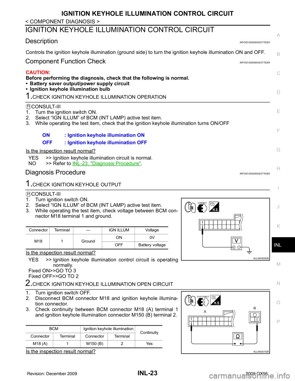
1.CHECK IGNITION KEYHOLE ILLUMINATION OPERATION
CONSULT-III
1. Turn the ignition switch ON.
2. Select “IGN ILLUM” of BCM (INT LAMP) active test item.
3. While operating the test item, check that the ignition keyhole illumination turns ON/OFF
Is the inspection result normal?
YES >> Ignition keyhole illumination circuit is normal.
NO >> Refer to INL-23, "
Diagnosis Procedure".
Diagnosis ProcedureINFOID:0000000003776265
1.CHECK IGNITION KEYHOLE OUTPUT
CONSULT-III
1. Turn ignition switch ON.
2. Select “IGN ILLUM” of BCM (INT LAMP) active test item.
3. While operating the test item, check voltage between BCM con- nector M18 terminal 1 and ground.
Is the inspection result normal?
YES >> Ignition keyhole illumination control circuit is operating normally.
Fixed ON>>GO TO 3
Fixed OFF>>GO TO 2
2.CHECK IGNITION KEYHOLE I LLUMINATION OPEN CIRCUIT
1. Turn ignition switch OFF.
2. Disconnect BCM connector M18 and ignition keyhole illumina- tion connector.
3. Check continuity between BCM connector M18 (A) terminal 1 and ignition keyhole illumination connector M150 (B) terminal 2.
Is the inspection result normal?
ON : Ignition keyhole illumination ON
OFF : Ignition keyhole illumination OFF
Connector Terminal — IGN ILLUM Voltage
M18 1 Ground ON
0V
OFF Battery voltage
ALLIA0420GB
BCM Ignition keyhole illumination
Continuity
Connector Terminal Connector Terminal
M18 (A) 1 M150 (B) 2 Yes
ALLIA0421GB
Revision: December 20092009 QX56
Page 2468 of 4171
INL-24
< COMPONENT DIAGNOSIS >
IGNITION KEYHOLE ILLUMINATION CONTROL CIRCUIT
YES >> Check ignition keyhole illumination for an open. If OK, replace BCM. Refer to BCS-56, "Removal
and Installation". If NG, replace ignition keyhole illumination.
NO >> Repair harness or connectors.
3.CHECK IGNITION KEYHOLE ILLUMINATION SHORT CIRCUIT
1. Turn ignition switch OFF.
2. Disconnect BCM connector M18 and ignition keyhole illumina- tion connector.
3. Check continuity between BCM connector M18 terminal 1 and ground.
Is the inspection result normal?
YES >> Check ignition keyhole illumination for a short circuit. If OK, replace BCM. Refer to BCS-56, "
Removal and
Installation". If NG, replace ignition keyhole illumination.
NO >> Repair harness or connectors.
Connector Terminal —Continuity
M18 1Ground No
ALLIA0422GB
Revision: December 20092009 QX56
Page 2500 of 4171

INL-56
< ECU DIAGNOSIS >
BCM (BODY CONTROL MODULE)
HEADLAMP SW1Headlamp switch OFF OFF
Headlamp switch 1st
ON
HEADLAMP SW2 Headlamp switch OFF
OFF
Headlamp switch 1st ON
HI BEAM SW High beam switch OFF
OFF
High beam switch HI ON
H/L WASH SW NOTE:
The item is indicated, but not monitored OFF
IGN ON SW Ignition switch OFF or ACC
OFF
Ignition switch ON ON
IGN SW CAN Ignition switch OFF or ACC
OFF
Ignition switch ON ON
INT VOLUME Wiper intermittent dial is in a dial position 1 - 7 1 - 7
I-KEY LOCK LOCK button of Intelligent Key is not pressed
OFF
LOCK button of Intelligent Key is pressed ON
I-KEY UNLOCK UNLOCK button of Intelligent Key is not pressed
OFF
UNLOCK button of Intelligent Key is pressed ON
KEY ON SW Mechanical key is removed from key cylinder
OFF
Mechanical key is inserted to key cylinder ON
OIL PRESS SW • Ignition switch OFF or ACC
• Engine running
OFF
Ignition switch ON ON
PASSING SW Other than lighting switch PASS
OFF
Lighting switch PASS ON
REAR DEF SW Rear window defogger switch OFF
OFF
Rear window defogger switch ON ON
RKE LOCK AND UN-
LOCK NOTE:
The item is indicated, but not monitored OFF
ON
RR WASHER SW Rear washer switch OFF
OFF
Rear washer switch ON ON
RR WIPER INT Rear wiper switch OFF
OFF
Rear wiper switch INT ON
RR WIPER ON Rear wiper switch OFF
OFF
Rear wiper switch ON ON
RR WIPER STOP Rear wiper stop position
OFF
Other than rear wiper stop position ON
TAIL LAMP SW Lighting switch OFF
OFF
Lighting switch 1ST ON
TRNK OPNR SW When back door opener switch is not pressed
OFF
When back door opener switch is pressed ON
TURN SIGNAL L Turn signal switch OFF
OFF
Turn signal switch LH ON
TURN SIGNAL R Turn signal switch OFF
OFF
Turn signal switch RH ON
VEHICLE SPEED While driving Equivalent to speedometer reading
Monitor Item
Condition Value/Status
Revision: December 20092009 QX56
Page 2502 of 4171

INL-58
< ECU DIAGNOSIS >
BCM (BODY CONTROL MODULE)
Te r m i n a lWire
color Signal name Signal
input/
output Measuring condition
Reference value or waveform
(Approx.)
Ignition
switch Operation or condition
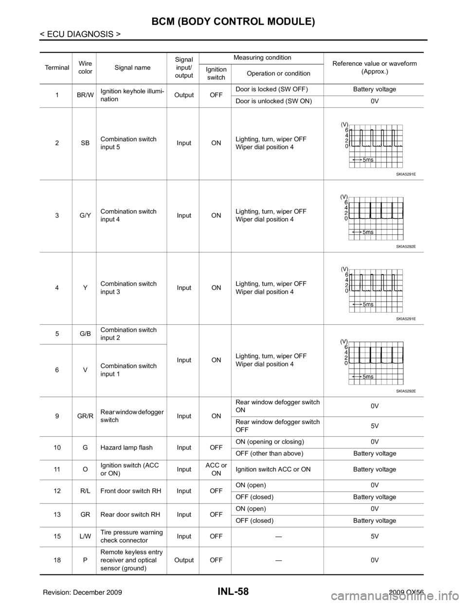
1BR/W Ignition keyhole illumi-
nation Output OFFDoor is locked (SW OFF)
Battery voltage
Door is unlocked (SW ON) 0V
2SB Combination switch
input 5 Input ON
Lighting, turn, wiper OFF
Wiper dial position 4
3G/Y Combination switch
input 4 Input ONLighting, turn, wiper OFF
Wiper dial position 4
4Y Combination switch
input 3 Input ON
Lighting, turn, wiper OFF
Wiper dial position 4
5G/B Combination switch
input 2
Input ONLighting, turn, wiper OFF
Wiper dial position 4
6V Combination switch
input 1
9GR/R Rear window defogger
switch
Input ONRear window defogger switch
ON
0V
Rear window defogger switch
OFF 5V
10 G Hazard lamp flash Input OFF ON (opening or closing)
0V
OFF (other than above) Battery voltage
11 O Ignition switch (ACC
or ON)
InputACC or
ON Ignition switch ACC or ON
Battery voltage
12 R/L Front door switch RH Input OFF ON (open)
0V
OFF (closed) Battery voltage
13 GR Rear door switch RH Input OFF ON (open)
0V
OFF (closed) Battery voltage
15 L/W Tire pressure warning
check connector
Input OFF
—5V
18 P Remote keyless entry
receiver and optical
sensor (ground)
Output OFF
—0V
SKIA5291E
SKIA5292E
SKIA5291E
SKIA5292E
Revision: December 20092009 QX56
Page 2503 of 4171

BCM (BODY CONTROL MODULE)INL-59
< ECU DIAGNOSIS >
C
DE
F
G H
I
J
K
M A
B
INL
N
O P
19 V/W Remote keyless entry
receiver (power sup-
ply) Output OFF Ignition switch OFF
20 G/W Remote keyless entry
receiver (signal) Input OFFStand-by (keyfob buttons re-
leased)
When remote keyless entry
receiver receives signal from
keyfob (keyfob buttons
pressed)
21 G NATS antenna amp. Input OFF
→
ON Ignition switch (OFF → ON) Just after turning ignition switch
ON: Pointer of tester should
move for approx. 1 second, then return to battery voltage.
22 W/V BUS — —Ignition switch ON or power
window timer operates
23 G/O Security indicator
lamp Output OFF
Goes OFF
→ illuminates (Ev-
ery 2.4 seconds) Battery voltage
→ 0V
25 BR NATS antenna amp. Input OFF
→
ON Ignition switch (OFF → ON) Just after turning ignition switch
ON: Pointer of tester should
move for approx. 1 second, then return to battery voltage.
26 Y/L Rear wiper auto stop
switch 2 Input ONRise up position (rear wiper
arm on stopper)
0V
A Position (full clockwise stop
position) 0V
Forward sweep (counterclock-
wise direction) Fluctuating
B Position (full counterclock-
wise stop position) Battery voltage
Reverse sweep (clockwise di-
rection) Fluctuating
27 W/R Compressor ON sig-
nal Input ONA/C switch OFF
5V
A/C switch ON 0V
Te r m i n a l
Wire
color Signal name Signal
input/
output Measuring condition
Reference value or waveform
(Approx.)
Ignition
switch Operation or condition
LIIA1893E
LIIA1894E
LIIA1895E
PIIA2344E
Revision: December 20092009 QX56