2009 INFINITI QX56 instrument panel
[x] Cancel search: instrument panelPage 2832 of 4171
PARKING BRAKE CONTROLPB-7
< ON-VEHICLE REPAIR >
C
DE
G H
I
J
K L
M A
B
PB
N
O P
ON-VEHICLE REPAIR
PARKING BRAKE CONTROL
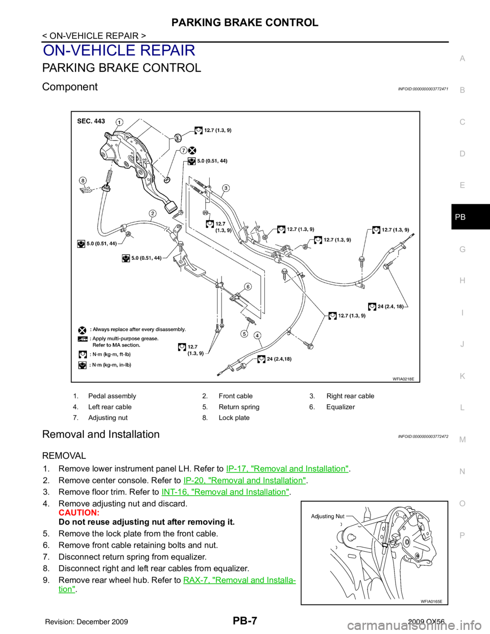
ComponentINFOID:0000000003772471
Removal and InstallationINFOID:0000000003772472
REMOVAL
1. Remove lower instrument panel LH. Refer to IP-17, "Removal and Installation".
2. Remove center console. Refer to IP-20, "
Removal and Installation".
3. Remove floor trim. Refer to INT-16, "
Removal and Installation".
4. Remove adjusting nut and discard. CAUTION:
Do not reuse adjusting nut after removing it.
5. Remove the lock plate from the front cable.
6. Remove front cable retaining bolts and nut.
7. Disconnect return spring from equalizer.
8. Disconnect right and left rear cables from equalizer.
9. Remove rear wheel hub. Refer to RAX-7, "
Removal and Installa-
tion".
1. Pedal assembly 2. Front cable3. Right rear cable
4. Left rear cable 5. Return spring6. Equalizer
7. Adjusting nut 8. Lock plate
WFIA0218E
WFIA0165E
Revision: December 20092009 QX56
Page 2956 of 4171
PWC-8
< FUNCTION DIAGNOSIS >
POWER WINDOW SYSTEM
Component Parts Location
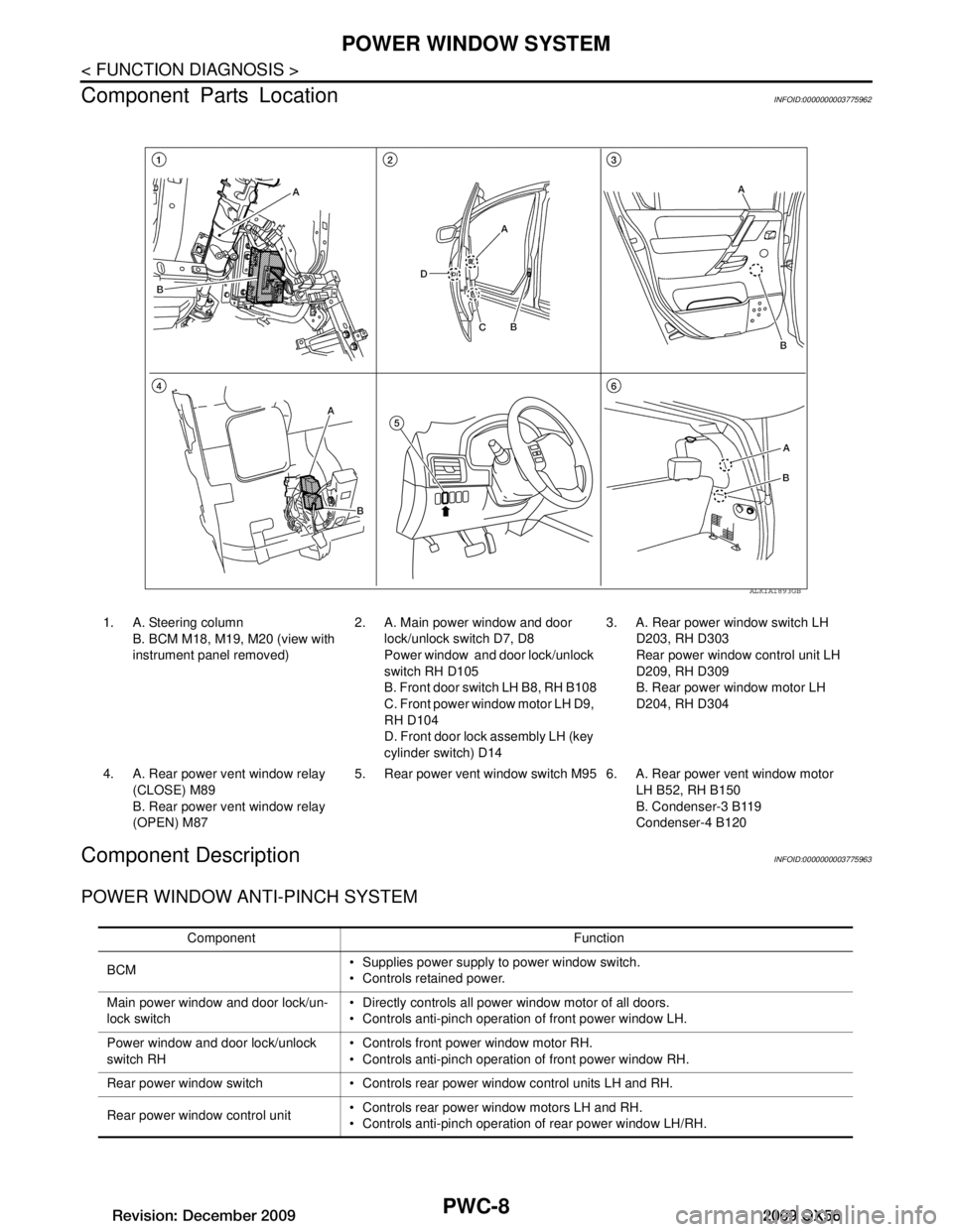
INFOID:0000000003775962
Component DescriptionINFOID:0000000003775963
POWER WINDOW ANTI-PINCH SYSTEM
ALKIA1893GB
1. A. Steering column B. BCM M18, M19, M20 (view with
instrument panel removed) 2. A. Main power window and door
lock/unlock switch D7, D8
Power window and door lock/unlock
switch RH D105
B. Front door switch LH B8, RH B108
C. Front power win dow motor LH D9,
RH D104
D. Front door lock assembly LH (key
cylinder switch) D14 3. A. Rear power window switch LH
D203, RH D303
Rear power window control unit LH
D209, RH D309
B. Rear power window motor LH
D204, RH D304
4. A. Rear power vent window relay (CLOSE) M89
B. Rear power ve nt window relay
(OPEN) M87 5. Rear power vent window switch M95 6. A. Rear power vent window motor
LH B52, RH B150
B. Condenser-3 B119
Condenser-4 B120
Component Function
BCM Supplies power supply to power window switch.
Controls retained power.
Main power window and door lock/un-
lock switch Directly controls all power window motor of all doors.
Controls anti-pinch operation of front power window LH.
Power window and door lock/unlock
switch RH Controls front power window motor RH.
Controls anti-pinch operation of front power window RH.
Rear power window switch Controls rear power window control units LH and RH.
Rear power window control unit Controls rear power window motors LH and RH.
Controls anti-pinch operation of rear power window LH/RH.
Revision: December 20092009 QX56
Page 3068 of 4171
PWC-120
< ON-VEHICLE REPAIR >
REAR POWER VENT WINDOW SWITCH
REAR POWER VENT WINDOW SWITCH
Removal and InstallationINFOID:0000000005867477
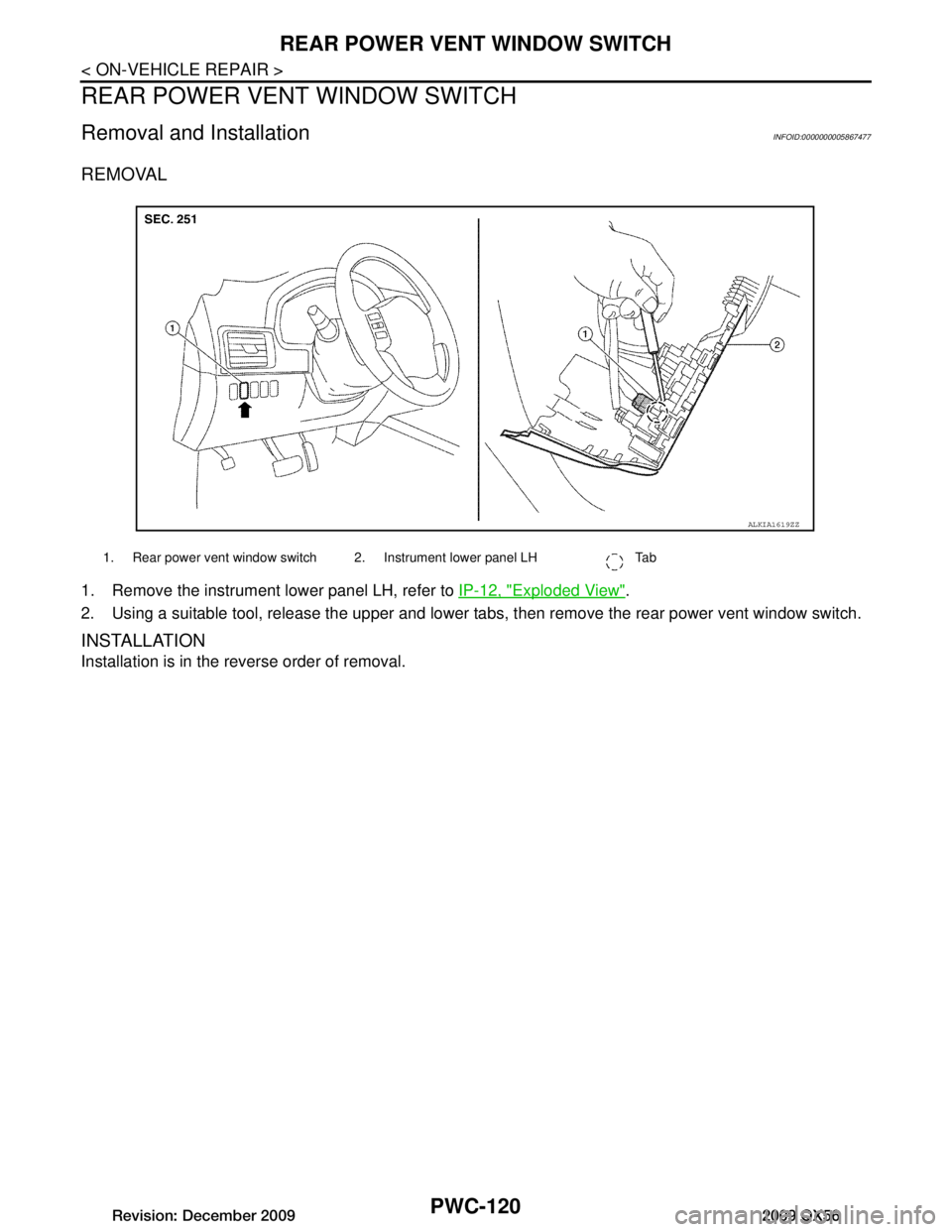
REMOVAL
1. Remove the instrument lower panel LH, refer to IP-12, "Exploded View".
2. Using a suitable tool, release the upper and lower tabs , then remove the rear power vent window switch.
INSTALLATION
Installation is in the reverse order of removal.
1. Rear power vent window switch 2. Instrument lower panel LH Tab
ALKIA1619ZZ
Revision: December 20092009 QX56
Page 3098 of 4171
SUNROOF SYSTEMRF-7
< FUNCTION DIAGNOSIS >
C
DE
F
G H
I
J
L
M A
B
RF
N
O P
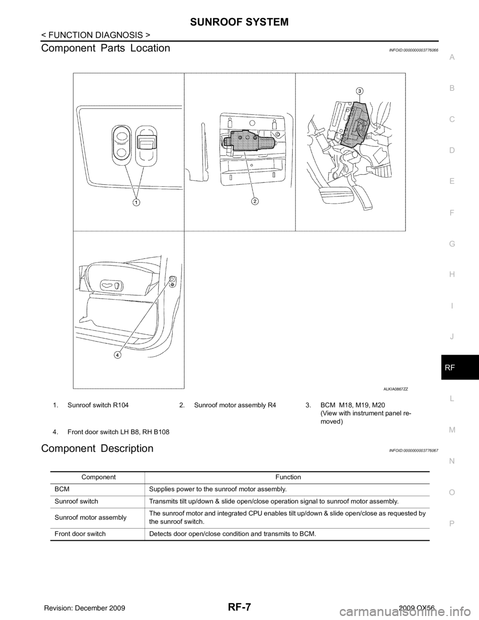
Component Parts LocationINFOID:0000000003776066
Component DescriptionINFOID:0000000003776067
ALKIA0867ZZ
1. Sunroof switch R104 2. Sunroof motor assembly R4 3. BCM M18, M19, M20
(View with instrument panel re-
moved)
4. Front door switch LH B8, RH B108
Component Function
BCM Supplies power to the sunroof motor assembly.
Sunroof switch Transmits tilt up/down & slide open/close operation signal to sunroof motor assembly.
Sunroof motor assembly The sunroof motor and integrated CPU enables tilt up/down & slide open/close as requested by
the sunroof switch.
Front door switch Detects door open/close condition and transmits to BCM.
Revision: December 20092009 QX56
Page 3134 of 4171
SQUEAK AND RATTLE TROUBLE DIAGNOSESRF-43
< SYMPTOM DIAGNOSIS >
C
DE
F
G H
I
J
L
M A
B
RF
N
O P
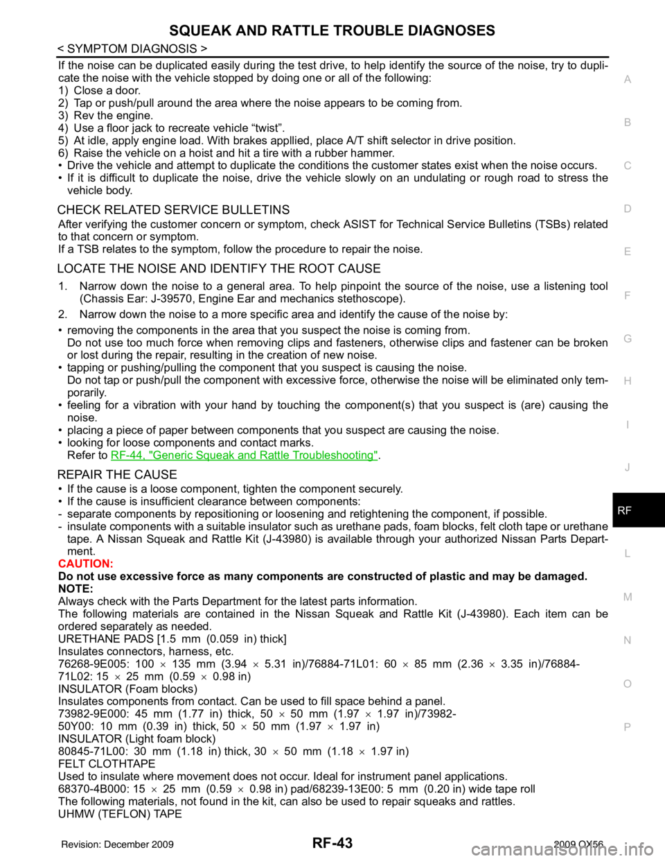
If the noise can be duplicated easily during the test drive, to help identify the source of the noise, try to dupli-
cate the noise with the vehicle stopped by doing one or all of the following:
1) Close a door.
2) Tap or push/pull around the area where the noise appears to be coming from.
3) Rev the engine.
4) Use a floor jack to recreate vehicle “twist”.
5) At idle, apply engine load. With brakes appllied, place A/T shift selector in drive position.
6) Raise the vehicle on a hoist and hit a tire with a rubber hammer.
• Drive the vehicle and attempt to duplicate the conditions the customer states exist when the noise occurs.
• If it is difficult to duplicate the noise, drive the vehicle slowly on an undulating or rough road to stress the
vehicle body.
CHECK RELATED SERVICE BULLETINS
After verifying the customer concern or symptom, check ASIST for Technical Service Bulletins (TSBs) related
to that concern or symptom.
If a TSB relates to the symptom, follow the procedure to repair the noise.
LOCATE THE NOISE AND IDENTIFY THE ROOT CAUSE
1. Narrow down the noise to a general area. To help pinpoint the source of the noise, use a listening tool (Chassis Ear: J-39570, Engine Ear and mechanics stethoscope).
2. Narrow down the noise to a more specific area and identify the cause of the noise by:
• removing the components in the area that you suspect the noise is coming from. Do not use too much force when removing clips and fasteners, otherwise clips and fastener can be broken
or lost during the repair, resulting in the creation of new noise.
• tapping or pushing/pulling the component that you suspect is causing the noise.
Do not tap or push/pull the component with excessive force, otherwise the noise will be eliminated only tem-
porarily.
• feeling for a vibration with your hand by touching the component(s) that you suspect is (are) causing the
noise.
• placing a piece of paper between components that you suspect are causing the noise.
• looking for loose components and contact marks. Refer to RF-44, "
Generic Squeak and Rattle Troubleshooting".
REPAIR THE CAUSE
• If the cause is a loose component, tighten the component securely.
• If the cause is insufficient clearance between components:
- separate components by repositioning or loos ening and retightening the component, if possible.
- insulate components with a suitable insulator such as urethane pads, foam blocks, felt cloth tape or urethane tape. A Nissan Squeak and Rattle Kit (J-43980) is av ailable through your authorized Nissan Parts Depart-
ment.
CAUTION:
Do not use excessive force as many components are constructed of plastic and may be damaged.
NOTE:
Always check with the Parts Department for the latest parts information.
The following materials are contained in the Niss an Squeak and Rattle Kit (J-43980). Each item can be
ordered separately as needed.
URETHANE PADS [1.5 mm (0.059 in) thick]
Insulates connectors, harness, etc.
76268-9E005: 100 ×135 mm (3.94 ×5.31 in)/76884-71L01: 60 ×85 mm (2.36 ×3.35 in)/76884-
71L02: 15 ×25 mm (0.59 ×0.98 in)
INSULATOR (Foam blocks)
Insulates components from contact. Can be used to fill space behind a panel.
73982-9E000: 45 mm (1.77 in) thick, 50 ×50 mm (1.97 ×1.97 in)/73982-
50Y00: 10 mm (0.39 in) thick, 50 ×50 mm (1.97 ×1.97 in)
INSULATOR (Light foam block)
80845-71L00: 30 mm (1.18 in) thick, 30 ×50 mm (1.18 ×1.97 in)
FELT CLOTHTAPE
Used to insulate where movement does not occur. Ideal for instrument panel applications.
68370-4B000: 15 ×25 mm (0.59 ×0.98 in) pad/68239-13E00: 5 mm (0.20 in) wide tape roll
The following materials, not found in the kit, can also be used to repair squeaks and rattles.
UHMW (TEFLON) TAPE
Revision: December 20092009 QX56
Page 3135 of 4171

RF-44
< SYMPTOM DIAGNOSIS >
SQUEAK AND RATTLE TROUBLE DIAGNOSES
Insulates where slight movement is present. Ideal for instrument panel applications.
SILICONE GREASE
Used in place of UHMW tape that will be visible or not fit. Will only last a few months.
SILICONE SPRAY
Use when grease cannot be applied.
DUCT TAPE
Use to eliminate movement.
CONFIRM THE REPAIR
Confirm that the cause of a noise is repaired by test driving the vehicle. Operate the vehicle under the same
conditions as when the noise originally occurred. Refer to the notes on the Diagnostic Worksheet.
Generic Squeak and Rattle TroubleshootingINFOID:0000000005877818
Refer to Table of Contents for specific component removal and installation information.
INSTRUMENT PANEL
Most incidents are caused by contact and movement between:
1. The cluster lid A and instrument panel
2. Acrylic lens and combination meter housing
3. Instrument panel to front pillar garnish
4. Instrument panel to windshield
5. Instrument panel pins
6. Wiring harnesses behind the combination meter
7. A/C defroster duct and duct joint
These incidents can usually be located by tapping or moving the components to duplicate the noise or by
pressing on the components while driving to stop the noise. Most of these incidents can be repaired by apply-
ing felt cloth tape or silicone spray (in hard to reach areas). Urethane pads can be used to insulate wiring har-
ness.
CAUTION:
Do not use silicone spray to isolate a squeak or rattle. If you saturate the ar ea with silicone, you will
not be able to recheck the repair.
CENTER CONSOLE
Components to pay attention to include:
1. Shifter assembly cover to finisher
2. A/C control unit and cluster lid C
3. Wiring harnesses behind audio and A/C control unit
The instrument panel repair and isolation pr ocedures also apply to the center console.
DOORS
Pay attention to the:
1. Finisher and inner panel making a slapping noise
2. Inside handle escutcheon to door finisher
3. Wiring harnesses tapping
4. Door striker out of alignment causing a popping noise on starts and stops
Tapping or moving the components or pressing on them wh ile driving to duplicate the conditions can isolate
many of these incidents. You can usually insulate the areas with felt cloth tape or insulator foam blocks from
the NISSAN Squeak and Rattle Kit (J-43980) to repair the noise.
TRUNK
Trunk noises are often caused by a loose jack or loose items put into the trunk by the owner.
In addition look for:
1. Trunk lid bumpers out of adjustment
2. Trunk lid striker out of adjustment
3. The trunk lid torsion bars knocking together
4. A loose license plate or bracket
Revision: December 20092009 QX56
Page 3271 of 4171
SQUEAK AND RATTLE TROUBLE DIAGNOSESSE-39
< SYMPTOM DIAGNOSIS >
C
DE
F
G H
I
K L
M A
B
SE
N
O P
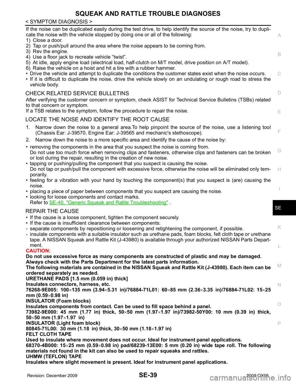
If the noise can be duplicated easily during the test drive, to help identify the source of the noise, try to dupli-
cate the noise with the vehicle stopped by doing one or all of the following:
1) Close a door.
2) Tap or push/pull around the area where the noise appears to be coming from.
3) Rev the engine.
4) Use a floor jack to recreate vehicle “twist”.
5) At idle, apply engine load (electrical load, half- clutch on M/T model, drive position on A/T model).
6) Raise the vehicle on a hoist and hit a tire with a rubber hammer.
• Drive the vehicle and attempt to duplicate the conditions the customer states exist when the noise occurs.
• If it is difficult to duplicate the noise, drive the vehicle slowly on an undulating or rough road to stress the vehicle body.
CHECK RELATED SERVICE BULLETINS
After verifying the customer concern or symptom, check ASIST for Technical Service Bulletins (TSBs) related
to that concern or symptom.
If a TSB relates to the symptom, follow the procedure to repair the noise.
LOCATE THE NOISE AND IDENTIFY THE ROOT CAUSE
1. Narrow down the noise to a general area.To help pinpoint the source of the noise, use a listening tool (Chassis Ear: J-39570, Engine Ear: J-39565 and mechanic's stethoscope).
2. Narrow down the noise to a more specific area and identify the cause of the noise by:
• removing the components in the area that you suspect the noise is coming from. Do not use too much force when removing clips and fasteners, otherwise clips and fasteners can be broken
or lost during the repair, resulting in the creation of new noise.
• tapping or pushing/pulling the component that you suspect is causing the noise.
Do not tap or push/pull the component with excessive force, otherwise the noise will be eliminated only tem-
porarily.
• feeling for a vibration with your hand by touching the component(s) that you suspect is (are) causing the
noise.
• placing a piece of paper between components that you suspect are causing the noise.
• looking for loose components and contact marks. Refer to SE-40, "
Generic Squeak and Rattle Troubleshooting" .
REPAIR THE CAUSE
• If the cause is a loose component, tighten the component securely.
• If the cause is insufficient clearance between components:
- separate components by repositioning or loos ening and retightening the component, if possible.
- insulate components with a suitable insulator such as urethane pads, foam blocks, felt cloth tape or urethane tape. A NISSAN Squeak and Rattle Kit (J-43980) is available through your authorized NISSAN Parts Depart-
ment.
CAUTION:
Do not use excessive force as many components are constructed of plastic and may be damaged.
Always check with the Parts Department for the latest parts information.
The following materials are contained in the NISSAN Squeak and Rattle Kit (J-43980). Each item can be
ordered separately as needed.
URETHANE PADS [1.5 mm (0.059 in) thick]
Insulates connectors, harness, etc.
76268-9E005: 100 ×135 mm (3.94 ×5.31 in)/76884-71L01: 60 ×85 mm (2.36× 3.35 in)/76884-71L02: 15× 25
mm (0.59 ×0.98 in)
INSULATOR (Foam blocks)
Insulates components from contact. Can be used to fill space behind a panel.
73982-9E000: 45 mm (1.77 in) thick, 50× 50 mm (1.97×1.97 in)/73982-50Y00: 10 mm (0.39 in) thick,
50× 50 mm (1.97 ×1.97 in)
INSULATOR (Light foam block)
80845-71L00: 30 mm (1.18 in) thick, 30 ×50 mm (1.18 ×1.97 in)
FELT CLOTH TAPE
Used to insulate where movement does not occu r. Ideal for instrument panel applications.
68370-4B000: 15 ×25 mm (0.59 ×0.98 in) pad/68239-13E00: 5 mm (0.20 in) wide tape roll. The following
materials not found in the kit can also be used to repair squeaks and rattles.
UHMW (TEFLON) TAPE
Insulates where slight movement is present. Ideal for instrument panel applications.
Revision: December 20092009 QX56
Page 3272 of 4171

SE-40
< SYMPTOM DIAGNOSIS >
SQUEAK AND RATTLE TROUBLE DIAGNOSES
SILICONE GREASE
Used instead of UHMW tape that will be visible or not fit.
Note: Will only last a few months.
SILICONE SPRAY
Use when grease cannot be applied.
DUCT TAPE
Use to eliminate movement.
CONFIRM THE REPAIR
Confirm that the cause of a noise is repaired by test driving the vehicle. Operate the vehicle under the same
conditions as when the noise originally occurred. Refer to the notes on the Diagnostic Worksheet.
Generic Squeak and Rattle TroubleshootingINFOID:0000000003775461
Refer to Table of Contents for specific component removal and installation information.
INSTRUMENT PANEL
Most incidents are caused by contact and movement between:
1. The cluster lid A and instrument panel
2. Acrylic lens and combination meter housing
3. Instrument panel to front pillar garnish
4. Instrument panel to windshield
5. Instrument panel mounting pins
6. Wiring harnesses behind the combination meter
7. A/C defroster duct and duct joint
These incidents can usually be located by tapping or moving the components to duplicate the noise or by
pressing on the components while driving to stop the noise. Most of these incidents can be repaired by apply-
ing felt cloth tape or silicone spray (in hard to reach areas). Urethane pads can be used to insulate wiring har-
ness.
CAUTION:
Do not use silicone spray to isolate a squeak or rattle. If you saturate the ar ea with silicone, you will
not be able to recheck the repair.
CENTER CONSOLE
Components to pay attention to include:
1. Shifter assembly cover to finisher
2. A/C control unit and cluster lid C
3. Wiring harnesses behind audio and A/C control unit
The instrument panel repair and isolation pr ocedures also apply to the center console.
DOORS
Pay attention to the:
1. Finisher and inner panel making a slapping noise
2. Inside handle escutcheon to door finisher
3. Wiring harnesses tapping
4. Door striker out of alignment causing a popping noise on starts and stops
Tapping or moving the components or pressing on them wh ile driving to duplicate the conditions can isolate
many of these incidents. You can usually insulate the areas with felt cloth tape or insulator foam blocks from
the NISSAN Squeak and Rattle Kit (J-43980) to repair the noise.
TRUNK
Trunk noises are often caused by a loose jack or loose items put into the trunk by the owner.
In addition look for:
1. Trunk lid bumpers out of adjustment
2. Trunk lid striker out of adjustment
3. The trunk lid torsion bars knocking together
4. A loose license plate or bracket
Revision: December 20092009 QX56