Page 3965 of 4171
AIR MIX DOOR MOTORVTL-25
< ON-VEHICLE REPAIR >
C
DE
F
G H
J
K L
M A
B
VTL
N
O P
AIR MIX DOOR MOTOR
ComponentINFOID:0000000003775276
Front Air Mix Door Motors - Front Heater and Cooling Unit Assembly
LJIA0139E
1. Front heater and cooling unit assembly 2. Intake door motor 3. Air mix door motor (driver)
4. Variable blower control 5. Air mix door motor (passenger) 6. Mode door motor
7. Defroster door motor
Revision: December 20092009 QX56
Page 3966 of 4171

VTL-26
< ON-VEHICLE REPAIR >
AIR MIX DOOR MOTOR
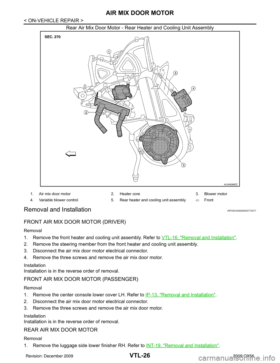
Rear Air Mix Door Motor - Rear Heater and Cooling Unit Assembly
Removal and InstallationINFOID:0000000003775277
FRONT AIR MIX DOOR MOTOR (DRIVER)
Removal
1. Remove the front heater and cooling unit assembly. Refer to VTL-16, "Removal and Installation".
2. Remove the steering member from the front heater and cooling unit assembly.
3. Disconnect the air mix door motor electrical connector.
4. Remove the three screws and remove the air mix door motor.
Installation
Installation is in the reverse order of removal.
FRONT AIR MIX DOOR MOTOR (PASSENGER)
Removal
1. Remove the center console lower cover LH. Refer to IP-13, "Removal and Installation".
2. Disconnect the air mix door motor electrical connector.
3. Remove the three screws and remove the air mix door motor.
Installation
Installation is in the reverse order of removal.
REAR AIR MIX DOOR MOTOR
Removal
1. Remove the luggage side lower finisher RH. Refer to INT-19, "Removal and Installation".
ALIIA0066ZZ
1. Air mix door motor2. Heater core 3. Blower motor
4. Variable blower control 5. Rear heater and cooling unit assembly ⇐Front
Revision: December 20092009 QX56
Page 3968 of 4171
VTL-28
< ON-VEHICLE REPAIR >
VARIABLE BLOWER CONTROL
VARIABLE BLOWER CONTROL
ComponentsINFOID:0000000003775278
Front Variable Blower Control - Front Heater and Cooling Unit Assembly
LJIA0139E
1. Front heater and cooling unit assembly 2. Intake door motor3. Air mix door motor (driver)
4. Variable blower control 5. Air mix door motor (passenger) 6. Mode door motor
7. Defroster door motor
Revision: December 20092009 QX56
Page 3969 of 4171

VARIABLE BLOWER CONTROLVTL-29
< ON-VEHICLE REPAIR >
C
DE
F
G H
J
K L
M A
B
VTL
N
O P
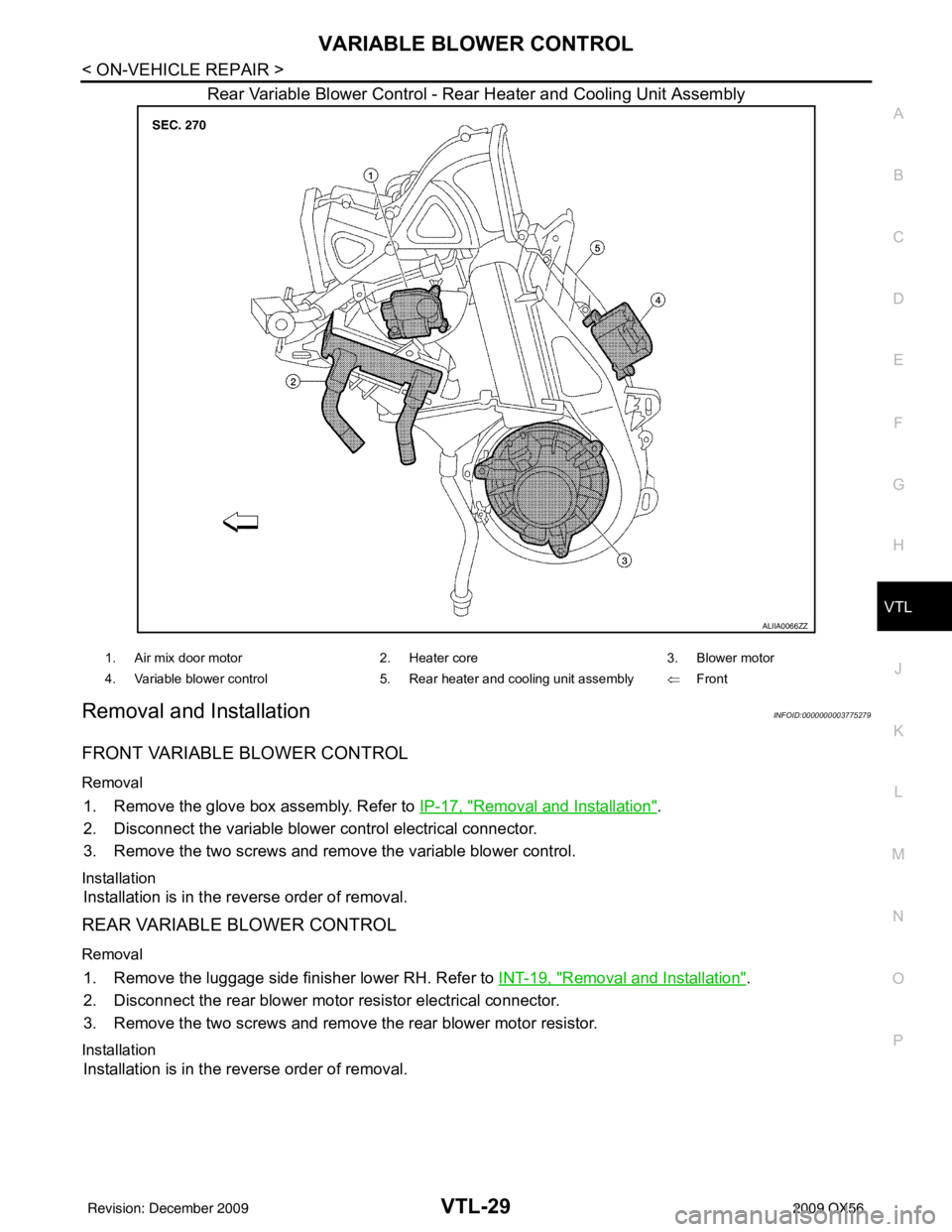
Rear Variable Blower Control - Rear Heater and Cooling Unit Assembly
Removal and InstallationINFOID:0000000003775279
FRONT VARIABLE BLOWER CONTROL
Removal
1. Remove the glove box assembly. Refer to IP-17, "Removal and Installation".
2. Disconnect the variable blower control electrical connector.
3. Remove the two screws and remove the variable blower control.
Installation
Installation is in the reverse order of removal.
REAR VARIABLE BLOWER CONTROL
Removal
1. Remove the luggage side finisher lower RH. Refer to INT-19, "Removal and Installation".
2. Disconnect the rear blower motor resistor electrical connector.
3. Remove the two screws and remove the rear blower motor resistor.
Installation
Installation is in the reverse order of removal.
ALIIA0066ZZ
1. Air mix door motor 2. Heater core 3. Blower motor
4. Variable blower control 5. Rear heater and cooling unit assembly ⇐Front
Revision: December 20092009 QX56
Page 3970 of 4171
VTL-30
< ON-VEHICLE REPAIR >
DUCTS AND GRILLES
DUCTS AND GRILLES
ComponentINFOID:0000000003775280
Ducts - Front Heater and Cooling Unit Assembly
AWIIA0090ZZ
1. Defroster nozzle2. LH side demister duct3. LH ventilator duct
4. RH side demister duct 5. RH ventilator duct6. Center ventilator duct
Revision: December 20092009 QX56
Page 3971 of 4171
DUCTS AND GRILLESVTL-31
< ON-VEHICLE REPAIR >
C
DE
F
G H
J
K L
M A
B
VTL
N
O P
Ducts - Rear Heater and Cooling Unit Assembly
7. Front heater and cooling unit assembly 8. Floor duct 9. Clips
10. Heat duct ⇐Front
AWIIA0091GB
1. Rear floor duct 2. Rear heater and cooling unit assembly 3. Rear lower overhead duct
4. Rear upper overhead duct ⇐Front
Revision: December 20092009 QX56
Page 3973 of 4171

DUCTS AND GRILLESVTL-33
< ON-VEHICLE REPAIR >
C
DE
F
G H
J
K L
M A
B
VTL
N
O P
Removal and InstallationINFOID:0000000003775281
CENTER CONSOLE HEAT DUCT AND RE AR FINISHER ASSEMBLY GRILLE
Removal
The center console must be removed and disassembled to remove the heat duct and rear finisher assembly
grille. Refer to IP-20, "
Removal and Installation".
Installation
Installation is in the reverse order of removal.
DEFROSTER NOZZLE
Removal
1. Remove the instrument panel trim. Refer to IP-13, "Removal and Installation".
2. Remove the front heater and cooling unit assembly. Refer to VTL-16, "
Removal and Installation".
3. Remove the defroster nozzle.
Installation
Installation is in the reverse order of removal.
RH AND LH SIDE DEMISTER DUCT
Removal
1. Remove the instrument panel trim. Refer to IP-13, "Removal and Installation".
2. Remove the RH or LH side demister duct screws.
3. Remove the RH or LH side demister duct.
Installation
Installation is in the reverse order of removal.
RH AND LH VENTILATOR DUCT
Removal
1. Remove the instrument panel trim. Refer to IP-13, "Removal and Installation".
2. Remove the front heater and cooling unit assembly. Refer to VTL-16, "
Removal and Installation".
3. Remove the RH or LH ventilator duct.
Installation
Installation is in the reverse order of removal.
CENTER VENTILATOR DUCT
Removal
1. Remove the instrument panel trim. Refer to IP-13, "Removal and Installation".
2. Remove the front heater and cooling unit assembly. Refer to VTL-16, "
Removal and Installation".
3. Remove the defroster nozzle.
4. Remove the RH and LH side demister ducts.
5. Remove the RH and LH ventilator ducts.
6. Remove the center ventilator duct.
Installation
Installation is in the reverse order of removal.
FLOOR DUCT
Removal
1. Remove the floor carpet. Refer to INT-16, "Removal and Installation".
2. Remove the two clips and remove the floor duct.
Installation
Installation is in the reverse order of removal.
Revision: December 20092009 QX56
Page 3975 of 4171
REFRIGERANT LINESVTL-35
< ON-VEHICLE REPAIR >
C
DE
F
G H
J
K L
M A
B
VTL
N
O P
REFRIGERANT LINES
Removal and Installation for Front EvaporatorINFOID:0000000003775282
Front Heater and Cooling Unit Assembly
REMOVAL
1. Remove the front heater core. Refer to VTL-19, "Removal and Installation".
AWIIA0086ZZ
1. Heater core cover 2. Heater core pipe bracket3. Heater core
4. Upper bracket 5. Upper heater and cooling unit case 6. A/C evaporator
7. Lower heater and cooling unit case 8. Blower motor 9. Variable blower control
Front
Revision: December 20092009 QX56