2009 Hyundai Sonata power steering
[x] Cancel search: power steeringPage 10 of 286

F9
1. Door lock/unlock button
2. Outside rearview mirror control switch*
3. Central door lock switch*
4. Power window lock switch*
5. Power window switches*
6. Trunk lid release lever
7. Fuel filler lid opener button
8. Panel Brightness Control Knob (Rheostat Switch)
9. Electronic Stability Control (ESC) Switch
CAUTION:
When installing a container of liquid air freshener inside the vehicle, do not place it near the instrument cluster
nor on the instrument panel surface. If there is any leakage from the air freshener onto these areas
(Instrument cluster, instrument panel or air ventilator), it may damage these parts. If the liquid from the air
freshener does leak onto these areas, wash them with water immediately.
!
10. Power Adjustable Pedals Switch*
11. Steering wheel tilt
12. Hood release lever
13. Brake pedal
14. Accelerator pedal
15. Clutch pedal*
16. Fuse box
* : if installed
Page 30 of 286
1
FEATURES OF YOUR HYUNDAI
17
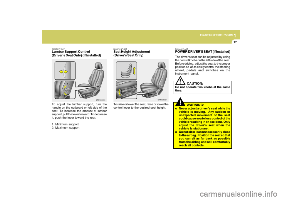
B080E01Y-AATLumbar Support Control
(Driver's Seat Only) (If Installed)To adjust the lumbar support, turn the
handle on the outboard or left side of the
seat. To increase the amount of lumbar
support, pull the lever forward. To decrease
it, push the lever toward the rear.
1. Minimum support
2. Maximum support
ONF038006
2
!
B090A02Y-AATPOWER DRIVER'S SEAT (If Installed)The driver's seat can be adjusted by using
the control knobs on the left side of the seat.
Before driving, adjust the seat to the proper
position so as to easily control the steering
wheel, pedals and switches on the
instrument panel.
CAUTION:
Do not operate two knobs at the same
time.
WARNING:
o Never adjust a driver’s seat while the
vehicle is moving. Any sudden or
unexpected movement of the seat
could cause you to lose control of the
vehicle resulting in an accident. Only
adjust the driver’s seat when the
vehicle is stationary.
o Do not sit or lean unnecessarily close
to the airbag. Position the seat so that
you can sit as far back as possible
from the airbag and still comfortably
reach all controls.
!
B080F01NF-GATSeat Height Adjustment
(Driver's Seat Only)To raise or lower the seat, raise or lower the
control lever to the desired seat height.
ONF038004
1
Page 165 of 286
2
DRIVING YOUR HYUNDAI
12
!
ANTI-LOCK BRAKE SYSTEM
(ABS)C120A01FC-AATThe Anti-Lock Brake System (ABS) is
designed to prevent wheel lock-up during
sudden braking or on hazardous road
surfaces. The ABS control module monitors
the wheel speed and controls the pressure
applied to each brake. Thus, in emergency
situations or on slick roads, ABS will
increase vehicle control during braking.NOTE:o A click sound may be heard in the
engine compartment when the ve-
hicle begins to move after the engine
is started. These conditions are nor-
mal and indicate that the anti-lock
brake system or Electronic Stability
Control is functioning properly.
o During ABS or ESC operation, a pul-
sation may be felt in the brake pedal
when the brakes are applied. Also, a
noise may be heard in the engine
compartment while braking. These
conditions are normal and indicate
that the anti-lock brake system or
Electronic Stability Control System is
functioning properly.
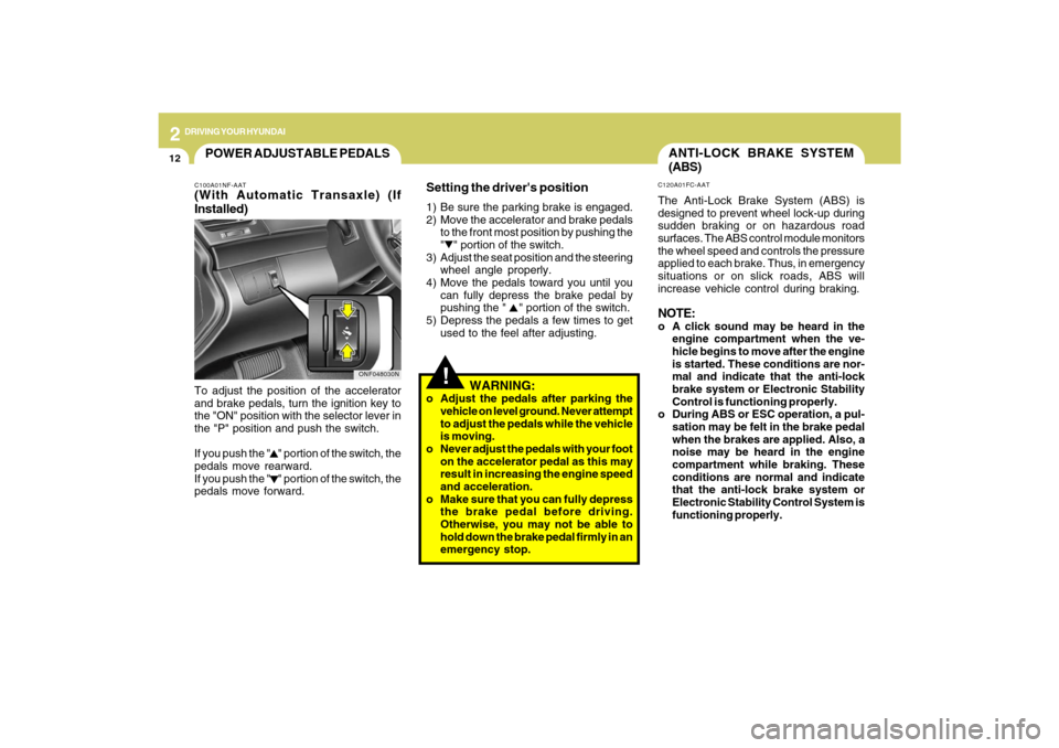
Setting the driver's position1) Be sure the parking brake is engaged.
2) Move the accelerator and brake pedals
to the front most position by pushing the
" " portion of the switch.
3) Adjust the seat position and the steering
wheel angle properly.
4) Move the pedals toward you until you
can fully depress the brake pedal by
pushing the " " portion of the switch.
5) Depress the pedals a few times to get
used to the feel after adjusting.
WARNING:
o Adjust the pedals after parking the
vehicle on level ground. Never attempt
to adjust the pedals while the vehicle
is moving.
o Never adjust the pedals with your foot
on the accelerator pedal as this may
result in increasing the engine speed
and acceleration.
o Make sure that you can fully depress
the brake pedal before driving.
Otherwise, you may not be able to
hold down the brake pedal firmly in an
emergency stop.
POWER ADJUSTABLE PEDALSC100A01NF-AAT(With Automatic Transaxle) (If
Installed)To adjust the position of the accelerator
and brake pedals, turn the ignition key to
the "ON" position with the selector lever in
the "P" position and push the switch.
If you push the " " portion of the switch, the
pedals move rearward.
If you push the " " portion of the switch, the
pedals move forward.
ONF048030N
Page 210 of 286
5
VEHICLE MAINTENANCE REQUIREMENTS
5
See Note *
1
See Note *
2
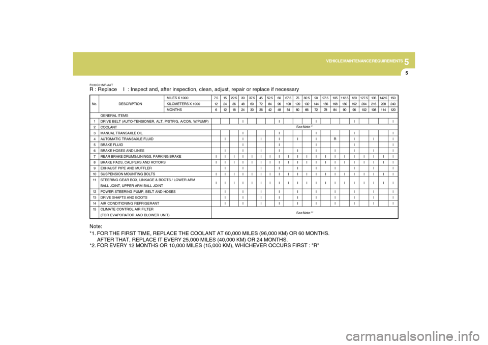
F030C01NF-AATR : Replace I : Inspect and, after inspection, clean, adjust, repair or replace if necessary
GENERAL ITEMS
DRIVE BELT (AUTO-TENSIONER, ALT, P/STR'G, A/CON, W/PUMP)
COOLANT
MANUAL TRANSAXLE OIL
AUTOMATIC TRANSAXLE FLUID
BRAKE FLUID
BRAKE HOSES AND LINES
REAR BRAKE DRUMS/LININGS, PARKING BRAKE
BRAKE PADS, CALIPERS AND ROTORS
EXHAUST PIPE AND MUFFLER
SUSPENSION MOUNTING BOLTS
STEERING GEAR BOX, LINKAGE & BOOTS / LOWER ARM
BALL JOINT, UPPER ARM BALL JOINT
POWER STEERING PUMP, BELT AND HOSES
DRIVE SHAFTS AND BOOTS
AIR CONDITIONING REFRIGERANT
CLIMATE CONTROL AIR FILTER
(FOR EVAPORATOR AND BLOWER UNIT) 1
2
3
4
5
6
7
8
9
10
11
12
13
14
15 No. DESCRIPTIONMILES X 1000
KILOMETERS X 1000
MONTHS7.5
12
6
I
I
I
I15
24
12
I
I
I
I
I
I
I
I
I
I22.5
36
18
I
I
I
I30
48
24
I
I
I
I
I
I
I
I
I
I
I
I
I37.5
60
30
I
I
I
I45
72
36
I
I
I
I
I
I
I
I
I
I52.5
84
42
I
I
I
I60
96
48
I
I
I
I
I
I
I
I
I
I
I
I
I67.5
108
54
I
I
I
I75
120
60
I
I
I
I
I
I
I
I
I
I82.5
132
66
I
I
I
I90
144
72
I
I
I
I
I
I
I
I
I
I
I
I
I97.5
156
78
I
I
I
I105
168
84
R
I
I
I
I
I
I
I
I
I112.5
180
90
I
I
I
I120
192
96
I
I
I
I
I
I
I
I
I
I
I
I
I127.5
204
102
I
I
I
I135
216
108
I
I
I
I
I
I
I
I
I
I142.5
228
114
I
I
I
I150
240
120
I
I
I
I
I
I
I
I
I
I
I
I
I
Note:
*1. FOR THE FIRST TIME, REPLACE THE COOLANT AT 60,000 MILES (96,000 KM) OR 60 MONTHS.
AFTER THAT, REPLACE IT EVERY 25,000 MILES (40,000 KM) OR 24 MONTHS.
*2. FOR EVERY 12 MONTHS OR 10,000 MILES (15,000 KM), WHICHEVER OCCURS FIRST : "R"
Page 214 of 286
5
VEHICLE MAINTENANCE REQUIREMENTS
9
F070L01A-AATo Suspension Mounting BoltsCheck the suspension connections for
looseness or damage. Retighten to the
specified torque.F070K01A-AATo Exhaust Pipe and MufflerVisually inspect the exhaust pipes, muffler
and
hangers for cracks, deterioration, or
damage. Start the engine and listen
carefully for any exhaust gas leakage.
Tighten connections or replace parts as
necessary.F070J01A-AATo Brake Pads, Calipers and RotorsCheck the pads for excessive wear, discs
for run out and wear, and calipers for fluid
leakage.
F070Q01A-AATo Air Conditioning RefrigerantCheck the air conditioning lines and con-
nections for leakage and damage. Check
air conditioning performance according to
the relevant shop manual if necessary.
F070P01A-AATo Drive Shafts and BootsCheck the drive shafts, boots and clamps
for cracks, deterioration, or damage.
Replace any damaged parts and, if
necessary, repack the grease.F070N01A-AATo Power Steering Pump, Belt and
HosesCheck the power steering pump and hoses
for leakage and damage. Replace any
damaged or leaking parts immediately.
Inspect the power steering belt for evidence
of cuts, cracks, excessive wear, oiliness
and proper tension. Replace or adjust it if
necessary.F070M01Y-AATo Steering Gear Box, Linkage &
Boots/Lower Arm Ball Joint, Upper
Arm Ball JointWith the vehicle stopped and engine off,
check for excessive free-play in the
steering wheel.
Check the linkage for bends or damage.
Check the dust boots and ball joints for
deterioration, cracks, or damage. Replace
any damaged parts.
Page 216 of 286
6
Engine Compartment .................................................... 6-2
General Checks ............................................................ 6-4
Checking the Engine Oil ............................................... 6-4
Changing the Engine Oil and Filter ................................ 6-6
Checking and Changing the Engine Coolant ................ 6-8
Changing the Air Cleaner Filter ...................................6-11
Checking the Transaxle Oil (Manual) .........................6-14
Checking the Transaxle Fluid (Automatic)..................6-15
Checking the Brakes ..................................................6-17
Air Conditioning Care..................................................6-18
Changing the Climate Control Air Filter .......................6-19
Checking Drive Belts ..................................................6-22
Checking and Replacing Fuses..................................6-22
Checking the Battery..................................................6-24
Power Steering Fluid Level .........................................6-26
Headlight Aiming Adjustment......................................6-27
Replacement of Light Bulbs ........................................6-28
Bulb Wattages.............................................................6-36
Fuse Panel Description...............................................6-37
DO-IT-YOURSELF MAINTENANCE
6
Page 217 of 286

6
DO-IT-YOURSELF MAINTENANCE
2
G010B01NF-AATENGINE COMPARTMENT
ONF018003
CAUTION:
When inspecting or servicing the
engine, you should handle tools
and other heavy objects
carefully so that the plastic cover
of the engine is not damaged.
!
1. Engine coolant reservoir
2. Engine oil filler cap
3. Brake fluid reservoir
4. Air cleaner5. Fuse box
6. Negative battery terminal
7. Positive battery terminal
8. Auto transaxle oil dipstick*9. Radiator cap
10. Engine oil dipstick
11. Windshield washer fluid reservoir
12. Power steering fluid reservoir
* : if installedGasoline Engine (2.4L)
Page 218 of 286

6
DO-IT-YOURSELF MAINTENANCE
3
8G010A01NF
G010A01NF-AATGasoline Engine (3.3L)
CAUTION:
When inspecting or servicing the
engine, you should handle tools
and other heavy objects
carefully so that the plastic cover
of the engine is not damaged.
!
1. Engine coolant reservoir
2. Engine oil filler cap
3. Brake fluid reservoir
4. Air cleaner5. Fuse box
6. Negative battery terminal
7. Positive battery terminal
8. Auto transaxle oil dipstick*9. Radiator cap
10. Engine oil dipstick
11. Windshield washer fluid reservoir
12. Power steering fluid reservoir
* : if installed