2009 Hyundai Sonata stop start
[x] Cancel search: stop startPage 187 of 286
36WHAT TO DO IN AN EMERGENCY
!
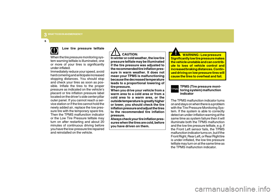
Low tire pressure telltale
When the tire pressure monitoring sys-
tem warning telltale is illuminated, one
or more of your tires is significantly
under-inflated.
Immediately reduce your speed, avoid
hard cornering and anticipate increased
stopping distances. You should stop
and check your tires as soon as pos-
sible. Inflate the tires to the proper
pressure as indicated on the vehicle’s
placard or tire inflation pressure label
located on the driver’s side center pillar
outer panel. If you cannot reach a ser-
vice station or if the tire cannot hold the
newly added air, replace the low pres-
sure tire with the temporary spare tire.
Then the TPMS malfunction indicator
or the Low Tire Pressure telltale may
turn on after restarting and about 20
minutes of continuous driving before
you have the low-pressure tire repaired
and reinstalled on the vehicle. CAUTION:
In winter or cold weather, the low tire
pressure telltale may be illuminated
if the tire pressure was adjusted to
the recommended tire inflation pres-
sure in warm weather. It does not
mean your TPMS is malfunctioning
because the decreased temperature
leads to a proportional lowering of
tire pressure.
When you drive your vehicle from a
warm area to a cold area or from a
cold area to a warm area, or the
outside temperature is greatly higher
or lower, you should check the tire
inflation pressure and adjust the tires
to the recommended tire inflation
pressure.
Always check your tire inflation pres-
sures when the tires are cold, before
you have driven on them.WARNING - Low pressure
Significantly low tire pressure makes
the vehicle unstable and can contrib-
ute to loss of vehicle control and
increased braking distances. Contin-
ued driving on low pressure tires will
cause the tires to overheat and fail.
TPMS (Tire pressure moni-
toring system) malfunction
indicator
The TPMS malfunction indicator turns
on and stays on when there is a problem
with the Tire Pressure Monitoring Sys-
tem. If the system is able to correctly
detect an under-inflation warning at the
same time as system failure then it will
illuminate both the TPMS malfunction
and the low tire pressure telltale, e.g. if
the Front Left sensor fails, the TPMS
malfunction indicator turns on, but if the
Front Right, Rear Left, or Rear Right tire
is under-inflated, the low tire pressure
telltale may turn on at the same time as
the TPMS malfunction indicator.
!
Page 214 of 286
5
VEHICLE MAINTENANCE REQUIREMENTS
9
F070L01A-AATo Suspension Mounting BoltsCheck the suspension connections for
looseness or damage. Retighten to the
specified torque.F070K01A-AATo Exhaust Pipe and MufflerVisually inspect the exhaust pipes, muffler
and
hangers for cracks, deterioration, or
damage. Start the engine and listen
carefully for any exhaust gas leakage.
Tighten connections or replace parts as
necessary.F070J01A-AATo Brake Pads, Calipers and RotorsCheck the pads for excessive wear, discs
for run out and wear, and calipers for fluid
leakage.
F070Q01A-AATo Air Conditioning RefrigerantCheck the air conditioning lines and con-
nections for leakage and damage. Check
air conditioning performance according to
the relevant shop manual if necessary.
F070P01A-AATo Drive Shafts and BootsCheck the drive shafts, boots and clamps
for cracks, deterioration, or damage.
Replace any damaged parts and, if
necessary, repack the grease.F070N01A-AATo Power Steering Pump, Belt and
HosesCheck the power steering pump and hoses
for leakage and damage. Replace any
damaged or leaking parts immediately.
Inspect the power steering belt for evidence
of cuts, cracks, excessive wear, oiliness
and proper tension. Replace or adjust it if
necessary.F070M01Y-AATo Steering Gear Box, Linkage &
Boots/Lower Arm Ball Joint, Upper
Arm Ball JointWith the vehicle stopped and engine off,
check for excessive free-play in the
steering wheel.
Check the linkage for bends or damage.
Check the dust boots and ball joints for
deterioration, cracks, or damage. Replace
any damaged parts.
Page 222 of 286
6
DO-IT-YOURSELF MAINTENANCE
7
!
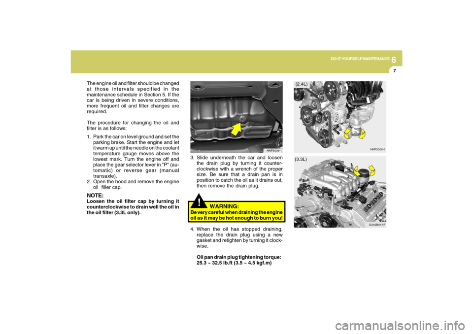
3. Slide underneath the car and loosen
the drain plug by turning it counter-
clockwise with a wrench of the proper
size. Be sure that a drain pan is in
position to catch the oil as it drains out,
then remove the drain plug.
4. When the oil has stopped draining,
replace the drain plug using a new
gasket and retighten by turning it clock-
wise.
Oil pan drain plug tightening torque:
25.3 ~ 32.5 lb.ft (3.5 ~ 4.5 kgf.m)
HNF5006-1
(2.4L)
(3.3L)
The engine oil and filter should be changed
at those intervals specified in the
maintenance schedule in Section 5. If the
car is being driven in severe conditions,
more frequent oil and filter changes are
required.
The procedure for changing the oil and
filter is as follows:
1. Park the car on level ground and set the
parking brake. Start the engine and let
it warm up until the needle on the coolant
temperature gauge moves above the
lowest mark. Turn the engine off and
place the gear selector lever in "P" (au-
tomatic) or reverse gear (manual
transaxle).
2. Open the hood and remove the engine
oil filler cap.NOTE:Loosen the oil filter cap by turning it
counterclockwise to drain well the oil in
the oil filter (3.3L only).
WARNING:
Be very careful when draining the engine
oil as it may be hot enough to burn you!
HNF5005-1
G040B01NF
Page 225 of 286
6
DO-IT-YOURSELF MAINTENANCE
10
3. Be sure your drain receptacle is in place.
Open the drain cock on the radiator.
Allow all the engine coolant to drain
from the cooling system, and then
securely close the drain cock.
4. Check Section 9 for the capacity of the
cooling system in your car. Then,
following the manufacturer's directions
on the engine coolant container, add
the appropriate quantity of coolant to
the radiator.
5. Slowly fill the radiator with the proper
coolant mixture (see the "Recom-
mended Engine Coolant in previous
page) until the fluid level stays up in the
radiator neck. And pump the radiator
hose in order to bleed the air.
HNF5008
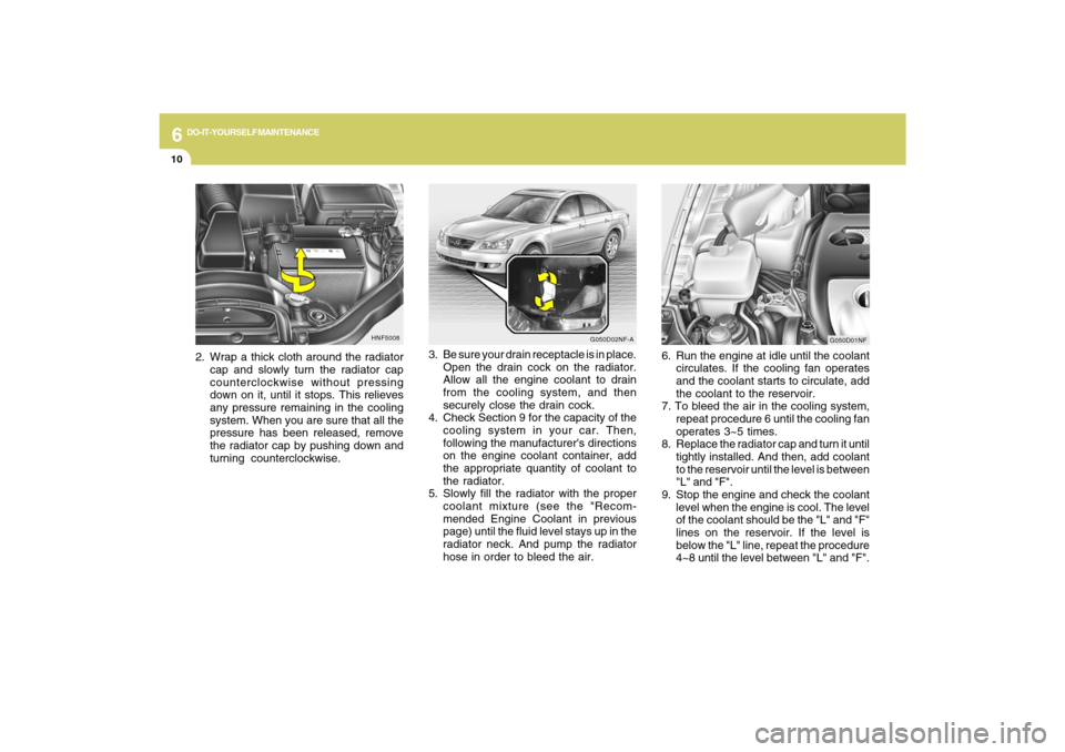
2. Wrap a thick cloth around the radiator
cap and slowly turn the radiator cap
counterclockwise without pressing
down on it, until it stops. This relieves
any pressure remaining in the cooling
system. When you are sure that all the
pressure has been released, remove
the radiator cap by pushing down and
turning counterclockwise.
G050D02NF-A
G050D01NF
6. Run the engine at idle until the coolant
circulates. If the cooling fan operates
and the coolant starts to circulate, add
the coolant to the reservoir.
7. To bleed the air in the cooling system,
repeat procedure 6 until the cooling fan
operates 3~5 times.
8. Replace the radiator cap and turn it until
tightly installed. And then, add coolant
to the reservoir until the level is between
"L" and "F".
9. Stop the engine and check the coolant
level when the engine is cool. The level
of the coolant should be the "L" and "F"
lines on the reservoir. If the level is
below the "L" line, repeat the procedure
4~8 until the level between "L" and "F".
Page 241 of 286
6
DO-IT-YOURSELF MAINTENANCE
26
G240A01A-AATPOWER STEERING HOSESIt is suggested that you check the power
steering hose connections for fluid leakage
at those intervals specified in the vehicle
maintenance schedule in Section 5.
The power steering hoses should be
replaced if there is severe surface crack-
ing, pulling, scuffing or worn spots.
Deterioration of the hose could cause
premature failure.
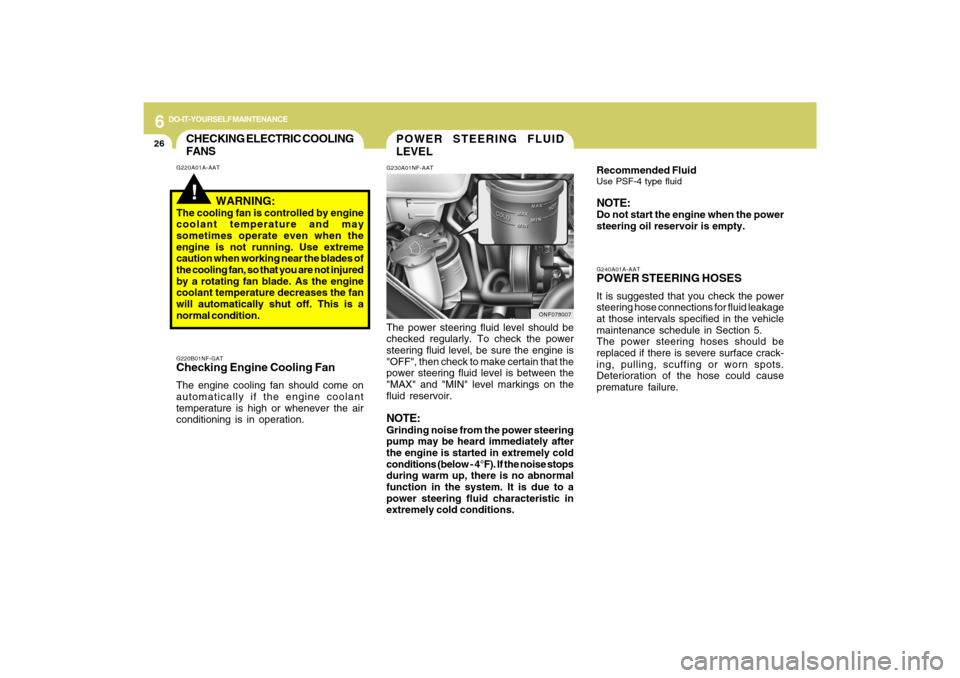
POWER STEERING FLUID
LEVELG230A01NF-AAT
Recommended FluidUse PSF-4 type fluidNOTE:Do not start the engine when the power
steering oil reservoir is empty.
ONF078007
The power steering fluid level should be
checked regularly. To check the power
steering fluid level, be sure the engine is
"OFF", then check to make certain that the
power steering fluid level is between the
"MAX" and "MIN" level markings on the
fluid reservoir.NOTE:Grinding noise from the power steering
pump may be heard immediately after
the engine is started in extremely cold
conditions (below - 4°F). If the noise stops
during warm up, there is no abnormal
function in the system. It is due to a
power steering fluid characteristic in
extremely cold conditions.
CHECKING ELECTRIC COOLING
FANS!
G220A01A-AAT
WARNING:
The cooling fan is controlled by engine
coolant temperature and may
sometimes operate even when the
engine is not running. Use extreme
caution when working near the blades of
the cooling fan, so that you are not injured
by a rotating fan blade. As the engine
coolant temperature decreases the fan
will automatically shut off. This is a
normal condition.G220B01NF-GATChecking Engine Cooling FanThe engine cooling fan should come on
automatically if the engine coolant
temperature is high or whenever the air
conditioning is in operation.
Page 253 of 286
6
DO-IT-YOURSELF MAINTENANCE
38
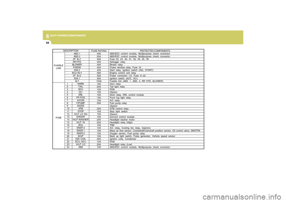
1
2
3
4
5
6
7
8
9
10
11
12
13
14
15
16
17
18
19
20
21
22
23
24
HORN
TAIL
ECU
IG1
DRL
FR FOG
A/CON
F/PUMP
DIODE
ATM
STOP
H/LP LO RH
S/ROOF
H/LP WASHER
H/LP HI
ECU
SNSR.3
SNSR.1
SNSR.2
B/UP
IGN COIL
ECU (IG1)
H/LP LO
ABS
PROTECTED COMPONENTS
ABS/ESC control module, Multipurpose check connector
ABS/ESC control module, Multipurpose check connector
Fuse 23, 24, 30, 31, 32, 33, 34, 35
Defogger relay
Blower relay
Power window relay, Fuse 16
Start relay, Ignition switch (IG2, START)
Engine control unit relay
Power connector 1/2, Fuse 21,22
Ignition switch (ACC, IG1)
Fusible Iink (ABS. 1, ABS. 2, RR HTD, BLOWER)
Horn relay
Tail light relay
PCM
(Spare)
Siren relay, DRL control module
Front fog light relay
A/C relay
Fuel pump relay
(Spare)
ATM control relay
Stop light switch
(Spare)
Sunroof control module
Headlight washer motor
Headlight relay (High)
TCM
A/C relay, Cooling fan relay, Injectors
Mass air flow sensor, Crankshaft/Camshaft position sensor, Oil control valve, SMATRA
Oxygen sensor, Fuel pump relay
Back up light switch, Pulse generator, Vehicle speed sensor
Ignition coils, Condenser
PCM
Headlight relay (Low)
ABS/ESC control module, Multipurpose check connector
ABS.1
ABS.2
I/P B+1
RR HTD
BLOWER
P/WDW
IGN.2
ECU RLY
I/P B+2
IGN.1
ALTFUSE RATING
40A
20A
40A
40A
40A
40A
40A
30A
30A
30A
150A
15A
20A
10A
10A
15A
15A
10A
20A
-
20A
15A
15A
15A
20A
20A
10A
10A
15A
15A
10A
20A
10A
20A
10A
DESCRIPTION
FUSIBLE
LINK
FUSE
Page 258 of 286
7
EMISSION CONTROL SYSTEMS
3
!
!
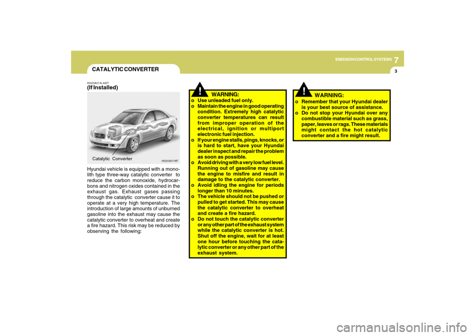
CATALYTIC CONVERTERH020A01A-AAT(If Installed)Hyundai vehicle is equipped with a mono-
lith type three-way catalytic converter to
reduce the carbon monoxide, hydrocar-
bons and nitrogen oxides contained in the
exhaust gas. Exhaust gases passing
through the catalytic converter cause it to
operate at a very high temperature. The
introduction of large amounts of unburned
gasoline into the exhaust may cause the
catalytic converter to overheat and create
a fire hazard. This risk may be reduced by
observing the following:Catalytic Converter
WARNING:
o Use unleaded fuel only.
o Maintain the engine in good operating
condition. Extremely high catalytic
converter temperatures can result
from improper operation of the
electrical, ignition or multiport
electronic fuel injection.
o If your engine stalls, pings, knocks, or
is hard to start, have your Hyundai
dealer inspect and repair the problem
as soon as possible.
o Avoid driving with a very low fuel level.
Running out of gasoline may cause
the engine to misfire and result in
damage to the catalytic converter.
o Avoid idling the engine for periods
longer than 10 minutes.
o The vehicle should not be pushed or
pulled to get started. This may cause
the catalytic converter to overheat
and create a fire hazard.
o Do not touch the catalytic converter
or any other part of the exhaust system
while the catalytic converter is hot.
Shut off the engine, wait for at least
one hour before touching the cata-
lytic converter or any other part of the
exhaust system.
H020A01NF
o Remember that your Hyundai dealer
is your best source of assistance.
o Do not stop your Hyundai over any
combustible material such as grass,
paper, leaves or rags. These materials
might contact the hot catalytic
converter and a fire might result.
WARNING:
Page 283 of 286

10
INDEX
4
Fuel
Capacity............................................................................ 9-2
Gauge..............................................................................1-55
Recommendations............................................................ 1-2
Fuel Filler Lid
Remote release ..............................................................1-85
Fuse Panel Description .....................................................6-37
Fuses..................................................................................6-22
G
General Checks ................................................................... 6-4
Glove Box ...........................................................................1-73
H
Hazard Warning System ....................................................1-65
Headlight
Aiming adjustment ..........................................................6-27
Replacement...................................................................6-28
Switch..............................................................................1-61
Heating and Cooling Control ............................................1-96
Heating and Ventilation
Air flow control ................................................... 1-98, 1-108
Air intake control switch ..................................... 1-99, 1-107
Bi-level heating .............................................................1-100
Defrosting/Defogging....................................................1-103
Fan speed control (Blower Control) .................. 1-97, 1-107
Temperature control .......................................................1-97
High-Mounted Rear Stop Light .........................................1-85
Hood Release ....................................................................1-87
Horn....................................................................................1-90I
Ignition Switch ...................................................................... 2-3
Instrument Cluster and Indicator Lights ............................1-48
Instrument Panel Light Control (Rheostat) .......................1-66
Interior Light .......................................................................1-72
Intermittent Wiper ...............................................................1-64
J
Jump Starting ....................................................................... 3-3
K
Key ........................................................................................ 1-3
If you lose your keys ......................................................3-18
Positions............................................................................ 2-3
L
Light Bulb Watages ............................................................6-36
Light Bulbs Replacement ..................................................6-28
Lubrication Chart .................................................................. 9-4
M
Maintenance Intervals
Explanation of scheduled maintenance items ................ 5-7
Maintenance under severe usage conditions ................. 5-6
Scheduled maintenance .................................................. 5-4
Service requirements ........................................................ 5-2
Mirrors
Day/night inside rearview ...............................................1-76
Homelink mirror ..............................................................1-77
Outside rearview .............................................................1-75
Outside rearview mirror heater ......................................1-76