Page 236 of 286

6
DO-IT-YOURSELF MAINTENANCE
21
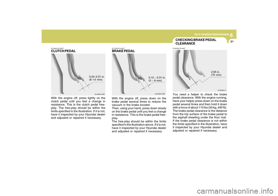
G170A01A-AATBRAKE PEDALWith the engine off, press down on the
brake pedal several times to reduce the
vacuum in the brake booster.
Then, using your hand, press down slowly
on the brake pedal until you feel a change
in resistance. This is the brake pedal free-
play.
The free-play should be within the limits
specified in the illustration above. If it is not,
have it inspected by your Hyundai dealer
and adjusted or repaired if necessary.
G160A01HR
0.12 ~ 0.31 in.
(3 ~ 8 mm)
CHECKING BRAKE PEDAL
CLEARANCEG180A01A-AATYou need a helper to check the brake
pedal clearance. With the engine running,
have your helper press down on the brake
pedal several times and then hold it down
with a force of about 110 lbs (50 kg, 490 N).
The brake pedal clearance is the distance
from the top surface of the brake pedal to
the asphalt sheeting under the floor mat.
If the brake pedal clearance is not within
the limits specified in the illustration, have
it inspected by your Hyundai dealer and
adjusted or repaired if necessary.
G180A01L
2.95 in.
(75 mm)
G160A01A-GATCLUTCH PEDALWith the engine off, press lightly on the
clutch pedal until you feel a change in
resistance. This is the clutch pedal free-
play. The free-play should be within the
limits specified in the illustration. If it is not,
have it inspected by your Hyundai dealer
and adjusted or repaired if necessary.
G160A01HR
0.24~0.51 in.
(6~13 mm)
Page 237 of 286

6
DO-IT-YOURSELF MAINTENANCE
22
Drive belts should be checked periodi-
cally for proper tension. At the same time,
belts should be examined for cracks, wear,
fraying or other evidence of deterioration
and replaced if necessary.
When a new belt is replaced, the belt
should be located within the pulley of flat
idler.
Belt routing should also be checked to be
sure there is no interference between the
belts and other parts of the engine.NOTE:Drive belt tension is adjusted automati-
cally by the auto tensioner.
CHECKING AND REPLACING
FUSESG200A01A-AATReplacing a Fusible LinkA fusible link will melt if the electrical circuits
from the battery are ever overloaded, thus
preventing damage to the entire wiring
harness. (This could be caused by a short
in the system drawing too much current.) If
this ever happens, have a Hyundai dealer
determine the cause, repair the system
and replace the fusible link. The fusible
links are located in a relay box in the
engine compartment for easy inspection.
ONF078020
G190A02NF-GATCHECKING DRIVE BELTS
G140D01NF
(2.4L)
(3.3L)
G140D02NF
Power steering pump
Compressor Water
pump pullyGenerator
Power steering
Compressor Water pump pully
Generator
Damper pulleyDamper pulley
Auto tensionerAuto tensioner
Page 238 of 286

6
DO-IT-YOURSELF MAINTENANCE
23
!
CAUTION:
When replacing a fusible link, never use
anything but a new fusible link with the
same or lower amperage rating. Never
use a piece of wire or a higher-rated
fusible link. This could result in serious
damage and create a fire hazard.
G200B02NF
4. Replace the blown fuse by pressing a
new fuse of the same rating into place.
The fuse should be a snug fit. If it is not,
have the fuse clip repaired or replaced
by a Hyundai dealer. If you do not have
a spare fuse, you may be able to borrow
a fuse of the same or lower rating from
an accessory you can temporarily get
along without (the radio or cigarette
lighter, for example). Always remember
to replace the borrowed fuse.
G200B01NF-AATReplacing Accessory FuseThe fuse box for the lights and other elec-
trical accessories will be found on the left
side of the instrument panel. Inside the box
you will find a list showing the circuits
protected by each fuse.
If any of your car's lights or other electrical
accessories stop working, a blown fuse
could be the reason. If the fuse has burned
out, you will see that the metal strip inside
the fuse has burned through. If you suspect
a blown fuse, follow this procedure:
1. Turn off the ignition and all other
switches.
2. Open the fuse box and examine each
fuse. Remove each fuse by pulling it
toward you (a small "fuse puller" tool is
contained in the relay and fuse box of
the engine room to simplify this
operation).
ONF078018
3. Be sure to check all other fuses, even if
you find one that appears to have burned
out.
Page 240 of 286

6
DO-IT-YOURSELF MAINTENANCE
25
!
G210B04A-AATChecking the BatteryKeep the battery clean. Any evidence of
corrosion around the battery posts or
terminals should be removed using a
solution of household baking soda and
warm water. After the battery terminals are
dry, cover them with a light coating of
grease.
PROPOSITION 65 WARNING:
Battery posts, terminals, and related
accessories contain lead and lead
compounds, chemicals known to the
state of California to cause cancer and
reproductive harm.
Batteries also contain other chemicals
known to the state of California to cause
cancer. Wash hands after handling.
!
!
WARNING:
Always read the following in-
structions carefully when han-
dling a battery.
Keep lighted cigarettes and all
other flames or sparks away
from the battery.
Hydrogen, which is a highly
combustible gas, is always
present in battery cells and
may explode if ignited.
Keep batteries out of the reach
of children because batteries
contain highly corrosive SUL-
FURIC ACID. Do not allow bat-
tery acid to contact your skin,
eyes, clothing or paint finish.
If any electrolyte gets into your
eyes, flush your eyes with
clean water for at least 15 min-
utes and get immediate medi-
cal attention. If possible, con-
tinue to apply water with a
sponge or cloth until medical
attention is received.If electrolyte gets on your skin,
thoroughly wash the contacted
area.
If you feel a pain or a burning
sensation, get medical
attention immediately.
Wear eye protection when
charging or working near a bat-
tery.
Always provide ventilation
when working in an enclosed
space.
o When lifting a plastic-cased battery,
excessive pressure on the case may
cause battery acid to leak, resulting in
personal injury. Lift with a battery
carrier or with your hands on opposite
corners.
o Never attempt to charge the battery
when the battery cables are con-
nected.
o The electrical ignition system works
with high voltage.
Never touch these components with
the engine running or the ignition
switched on.
WARNING:
Page 241 of 286

6
DO-IT-YOURSELF MAINTENANCE
26
G240A01A-AATPOWER STEERING HOSESIt is suggested that you check the power
steering hose connections for fluid leakage
at those intervals specified in the vehicle
maintenance schedule in Section 5.
The power steering hoses should be
replaced if there is severe surface crack-
ing, pulling, scuffing or worn spots.
Deterioration of the hose could cause
premature failure.
POWER STEERING FLUID
LEVELG230A01NF-AAT
Recommended FluidUse PSF-4 type fluidNOTE:Do not start the engine when the power
steering oil reservoir is empty.
ONF078007
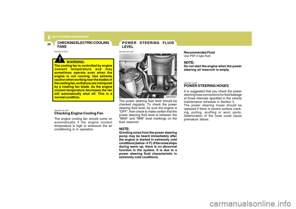
The power steering fluid level should be
checked regularly. To check the power
steering fluid level, be sure the engine is
"OFF", then check to make certain that the
power steering fluid level is between the
"MAX" and "MIN" level markings on the
fluid reservoir.NOTE:Grinding noise from the power steering
pump may be heard immediately after
the engine is started in extremely cold
conditions (below - 4°F). If the noise stops
during warm up, there is no abnormal
function in the system. It is due to a
power steering fluid characteristic in
extremely cold conditions.
CHECKING ELECTRIC COOLING
FANS!
G220A01A-AAT
WARNING:
The cooling fan is controlled by engine
coolant temperature and may
sometimes operate even when the
engine is not running. Use extreme
caution when working near the blades of
the cooling fan, so that you are not injured
by a rotating fan blade. As the engine
coolant temperature decreases the fan
will automatically shut off. This is a
normal condition.G220B01NF-GATChecking Engine Cooling FanThe engine cooling fan should come on
automatically if the engine coolant
temperature is high or whenever the air
conditioning is in operation.
Page 242 of 286

6
DO-IT-YOURSELF MAINTENANCE
27
FOR MORE INFORMATION
ABOUT YOUR HYUNDAIG250A01A-AATIf you desire additional information about
maintaining and servicing your Hyundai,
you may purchase a factory Shop Manual
at your Hyundai dealer's parts department.
This is the same manual used by
dealership technicians and while it is highly
technical it can be useful in obtaining a
better understanding of your car and how
it works.
HEADLIGHT AIMING ADJUST-
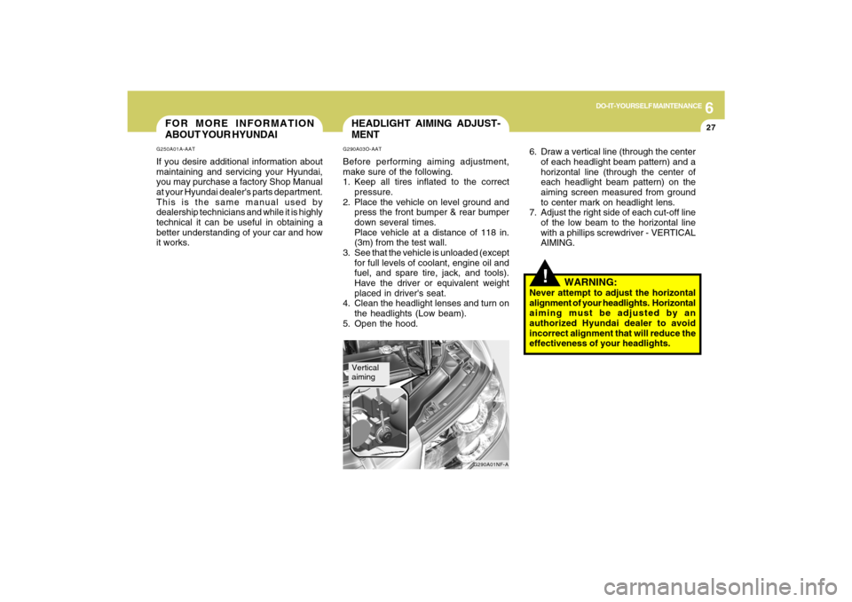
MENTG290A03O-AATBefore performing aiming adjustment,
make sure of the following.
1. Keep all tires inflated to the correct
pressure.
2. Place the vehicle on level ground and
press the front bumper & rear bumper
down several times.
Place vehicle at a distance of 118 in.
(3m) from the test wall.
3. See that the vehicle is unloaded (except
for full levels of coolant, engine oil and
fuel, and spare tire, jack, and tools).
Have the driver or equivalent weight
placed in driver's seat.
4. Clean the headlight lenses and turn on
the headlights (Low beam).
5. Open the hood.
G290A01NF-A
Vertical
aiming
!
6. Draw a vertical line (through the center
of each headlight beam pattern) and a
horizontal line (through the center of
each headlight beam pattern) on the
aiming screen measured from ground
to center mark on headlight lens.
7. Adjust the right side of each cut-off line
of the low beam to the horizontal line
with a phillips screwdriver - VERTICAL
AIMING.
WARNING:
Never attempt to adjust the horizontal
alignment of your headlights. Horizontal
aiming must be adjusted by an
authorized Hyundai dealer to avoid
incorrect alignment that will reduce the
effectiveness of your headlights.
Page 244 of 286
6
DO-IT-YOURSELF MAINTENANCE
29
Replacement instructions:
1. Allow the bulb to cool. Wear eye
protection.
2. Open the engine hood.
3. Always grasp the bulb by its base, avoid
touching the glass.G270A01NF-AATHEADLIGHT, FRONT TURN SIGNAL
LIGHT AND FRONT FOG LIGHT
Headlight and Front Turn Signal
Light
ONF078024
Headlight (Low beam)
Turn signal light
Front position light
Front Fog LightHeadlight
(High beam)
ONF078023N
4. Using a socket wrench of the correct
size, remove the headlight assembly
mounting bolts and bumper mounting
bolt.
HNF5024
5. Disconnect the power cord from the
back of the headlight.
Page 252 of 286
6
DO-IT-YOURSELF MAINTENANCE
37
FUSE PANEL DESCRIPTIONG200C01NF-AATEngine Compartment
NOTE:Not all fuse panel descriptions in this manual may be applicable to your vehicle. It is accurate at the time of printing. When you
inspect the fuse box on your vehicle, refer to the fuse box label.
HNF4005-1