Page 274 of 340
731
Maintenance
✽✽NOTICE
“C” (COLD) range is for reference only
and should NOT be used to determinetransaxle fluid level. ✽
✽
NOTICE
New automatic transaxle fluid should be
red. The red dye is added so the assem-bly plant can identify it as automatic
transaxle fluid and distinguish it from
engine oil or antifreeze. The red dye,
which is not an indicator of fluid quali-
ty, is not permanent. As the vehicle isdriven, the automatic transaxle fluid
will begin to look darker. The colour
may eventually appear light brown.
Therefore, have an authorised
HYUNDAI dealer change the automatictransaxle fluid according to theScheduled Maintenance at the begin-ning of this section.
Use only the specified automatic
transaxle fluid. (Refer to “Recommended
lubricants and capacities” in section 9.) G100200AFD-EA Changing the automatic transaxle fluid
Have automatic transaxle fluid changed
by an authorised HYUNDAI dealeraccording to the Maintenance Scheduleat the beginning of this section.
WARNING - Transaxle fluid
The transaxle fluid level should be
checked when the engine is at nor-
mal operating temperature. This
means that the engine, radiator,
radiator hose and exhaust system
etc., are very hot. Exercise great
care not to burn yourself during
this procedure.
WARNING - Parking brake
To avoid sudden movement of the
vehicle, apply parking brake and
depress the brake pedal before
moving the shift lever.
CAUTION
Low fluid level causes transaxle slippage. Overfilling can causefoaming, loss of fluid and transaxle malfunction.
The use of a non-specified fluid could result in transaxle malfunc-tion and failure.
Page 276 of 340
733
Maintenance
FUEL FILTER (FOR DIESEL)
G150100AFD-EA
Draining water from fuel filter
The fuel filter for diesel engine plays an
important role of separating water from
fuel and accumulating the water in itsbottom.
If water accumulates in the fuel filter, the
warning light comes on when the ignition
switch is in the ON position.
If the light is turned on, take your car to
the authorised HYUNDAI dealer and
have drain the water and checked thesystem. G150200AFD
Fuel filter cartridge replacement
✽✽NOTICE
When replacing the fuel filter cartridge, use HYUNDAI genuine parts.
ONF055004
CAUTION
If the water accumulated in the fuel filter is not drained at proper times,
damages to the major parts such asthe fuel system can be caused bywater permeation in the fuel filter.
Page 284 of 340
741
Maintenance
G190200AUN
Battery recharging
Your vehicle has a maintenance-free,
calcium-based battery.
If the battery becomes discharged in ashort time (because, for example, the
headlights or interior lights were left on
while the vehicle was not in use),
recharge it by slow charging (trickle)
for 10 hours.
If the battery gradually discharges because of high electric load while the
vehicle is being used, recharge it at 20-
30A for two hours.(Continued)
When lifting a plastic-cased bat- tery, excessive pressure on the
case may cause battery acid to
leak, resulting in personal injury.
Lift with a battery carrier or with
your hands on opposite corners.
Never attempt to recharge the battery when the battery cablesare connected.
The electrical ignition system works with high voltage. Never
touch these components with theengine running or the ignition
switched on.
Failure to follow the above warn-
ings can result in serious bodily
injury or death.WARNING - Recharging
battery
When recharging the battery,
observe the following precautions:
The battery must be removed from the vehicle and placed in an area with good ventilation.
Do not allow cigarettes, sparks, or flame near the battery.
Watch the battery during charg- ing, and stop or reduce the charg-
ing rate if the battery cells begin
gassing (boiling) violently or if
the temperature of the electrolyte
of any cell exceeds 49°C (120°F).
Wear eye protection when check- ing the battery during charging.
(Continued)
Page 296 of 340
753
Maintenance
FUSES
G210000AFD-EA
A vehicle’s electrical system is protected
from electrical overload damage by
fuses. This vehicle has 2 (or 3) fuse panels, one
located in the driver’s side panel bolster,
the other in the engine compartment
near the battery.
If any of your vehicle’s lights, acces-
sories, or controls do not work, check the
appropriate circuit fuse. If a fuse has
blown, the element inside the fuse will bemelted.
If the electrical system does not work,
first check the driver’s side fuse panel.
Always replace a blown fuse with one of
the same rating.
If the replacement fuse blows, this indi-
cates an electrical problem. Avoid using
the system involved and immediately
consult an authorised HYUNDAI dealer.
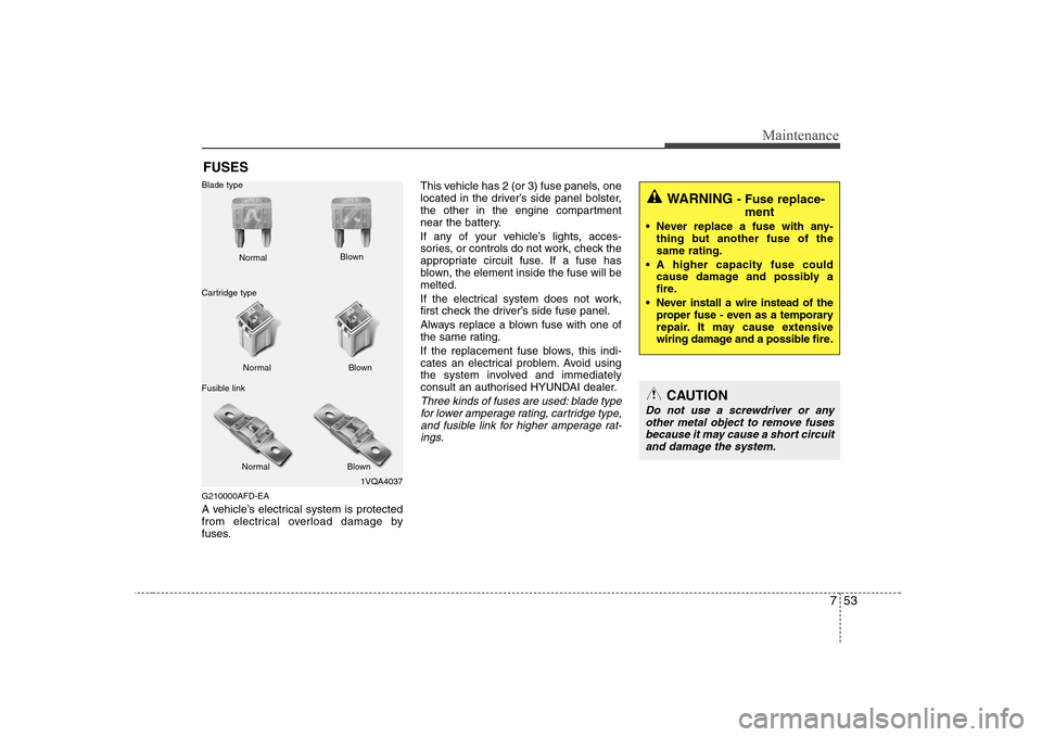
Three kinds of fuses are used: blade type
for lower amperage rating, cartridge type,
and fusible link for higher amperage rat-ings.
1VQA4037
Normal
Normal
Blade type
Cartridge type
Fusible link Blown
Blown
Normal Blown
WARNING - Fuse replace-
ment
Never replace a fuse with any- thing but another fuse of the same rating.
A higher capacity fuse could cause damage and possibly a
fire.
Never install a wire instead of the proper fuse - even as a temporary
repair. It may cause extensive
wiring damage and a possible fire.
CAUTION
Do not use a screwdriver or any
other metal object to remove fuses because it may cause a short circuit
and damage the system.
Page 297 of 340
Maintenance
54
7
G210100AUN-EA
Inner panel fuse replacement
1. Turn the ignition switch and all other
switches off.
2. Open the fuse panel cover. 3. Pull the suspected fuse straight out.
Use the removal tool provided in the
engine compartment fuse panel.
4. Check the removed fuse; replace it if it is blown.
5. Push in a new fuse of the same rating, and make sure it fits tightly in the clips.
If it fits loosely, consult an authorised
HYUNDAI dealer.
If you do not have a spare, use a fuse of the same rating from a circuit you may not need for operating the vehicle, suchas the cigar lighter fuse.
If the headlights or other electrical com-
ponents do not work and the fuses are
OK, check the fuse block in the engine
compartment. If a fuse is blown, it mustbe replaced.
ONF078018R
Driver’s side panel
ONF078019
Page 303 of 340
Maintenance
60
7
Engine compartment
Description Fuse rating Protected component
ABS.1 40A ABS/ESP control module, Multipurpose check connector
ABS.2 20A ABS/ESP control module, Multipurpose check connector
I/P B+1 40A Fuse 23, 24, 30, 31, 32, 33, 34, 35
RR HTD 40A Defogger relay
BLOWER 40A Blower relay
Fusible link P/WDW 40A Power window relay, Fuse 16 IGN.2 40A Start relay, Ignition switch (IG2, START)
ECU RLY 30A Engine control unit relay
I/P B+2 30A Power connector 1/2, Fuse 21,22
IGN.1 30A Ignition switch (ACC, IG1)
ALT 150A Fusible Iink (ABS. 1, ABS. 2, RR HTD, BLOWER)
1 HORN 15A Horn relay
2 TAIL 20A Tail light relay
3 ECU 10A PCM
4 IG1 10A DSL TCU
5 DRL 15A Siren relay, DRL control module
6 FR FOG 15A Front fog light relay
Fuse 7 A/CON 10A A/C relay 8 F/PUMP 20A Fuel pump relay
9 DIODE - (Spare)
10 ATM 20A ATM control relay, TCU
11 STOP 15A Stop light switch
12 H/LP LO RH 15A (Spare)
13 S/ROOF 15A Sunroof control module
Page 304 of 340
761
Maintenance
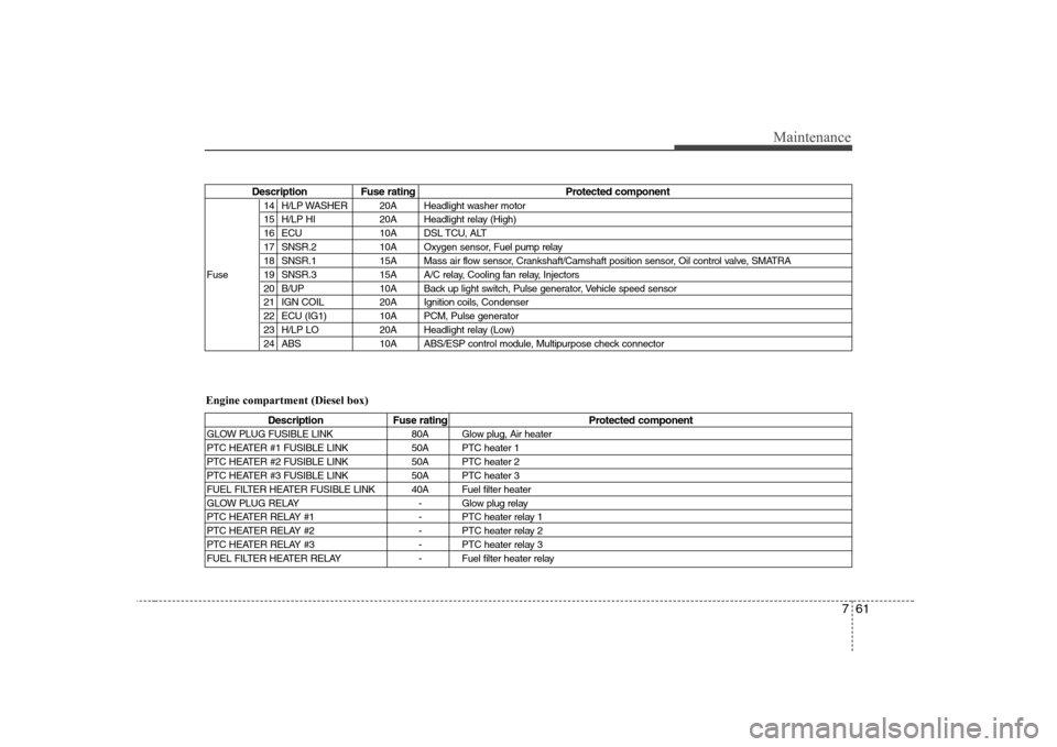
Description Fuse rating Protected component14 H/LP WASHER 20A Headlight washer motor
15 H/LP HI 20A Headlight relay (High)
16 ECU 10A DSL TCU, ALT
17 SNSR.2 10A Oxygen sensor, Fuel pump relay
18 SNSR.1 15A Mass air flow sensor, Crankshaft/Camshaft position sensor, Oil control valve, SMATRA
Fuse 19 SNSR.3 15A A/C relay, Cooling fan relay, Injectors 20 B/UP 10A Back up light switch, Pulse generator, Vehicle speed sensor
21 IGN COIL 20A Ignition coils, Condenser
22 ECU (IG1) 10A PCM, Pulse generator
23 H/LP LO 20A Headlight relay (Low)
24 ABS 10A ABS/ESP control module, Multipurpose check connector
Description Fuse rating Protected component
GLOW PLUG FUSIBLE LINK 80A Glow plug, Air heater
PTC HEATER #1 FUSIBLE LINK 50A PTC heater 1
PTC HEATER #2 FUSIBLE LINK 50A PTC heater 2
PTC HEATER #3 FUSIBLE LINK 50A PTC heater 3
FUEL FILTER HEATER FUSIBLE LINK 40A Fuel filter heater
GLOW PLUG RELAY - Glow plug relay
PTC HEATER RELAY #1 - PTC heater relay 1
PTC HEATER RELAY #2 - PTC heater relay 2
PTC HEATER RELAY #3 - PTC heater relay 3
FUEL FILTER HEATER RELAY - Fuel filter heater relay
Engine compartment (Diesel box)
Page 311 of 340
Maintenance
68
7
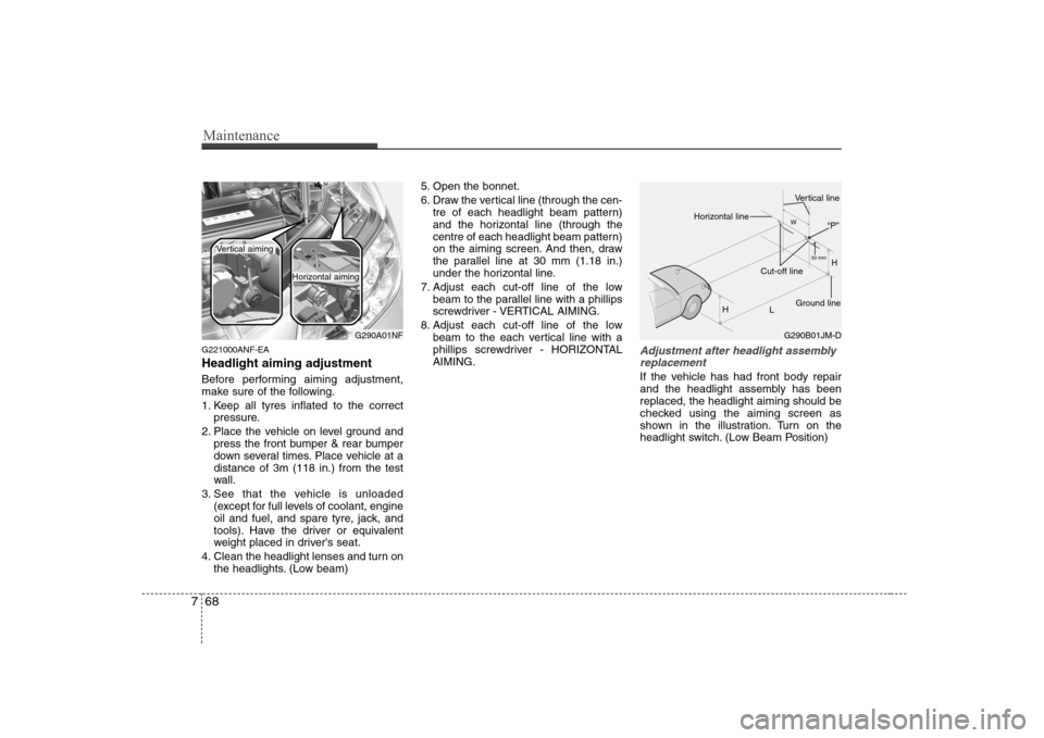
G221000ANF-EA Headlight aiming adjustment
Before performing aiming adjustment,
make sure of the following.
1. Keep all tyres inflated to the correct
pressure.
2. Place the vehicle on level ground and press the front bumper & rear bumper
down several times. Place vehicle at adistance of 3m (118 in.) from the test
wall.
3. See that the vehicle is unloaded (except for full levels of coolant, engine
oil and fuel, and spare tyre, jack, and
tools). Have the driver or equivalent
weight placed in driver's seat.
4. Clean the headlight lenses and turn on the headlights. (Low beam) 5. Open the bonnet.
6. Draw the vertical line (through the cen-
tre of each headlight beam pattern)
and the horizontal line (through the
centre of each headlight beam pattern)
on the aiming screen. And then, draw
the parallel line at 30 mm (1.18 in.)
under the horizontal line.
7. Adjust each cut-off line of the low beam to the parallel line with a phillips
screwdriver - VERTICAL AIMING.
8. Adjust each cut-off line of the low beam to the each vertical line with a
phillips screwdriver - HORIZONTALAIMING.Adjustment after headlight assembly
replacement
If the vehicle has had front body repair
and the headlight assembly has beenreplaced, the headlight aiming should be
checked using the aiming screen as
shown in the illustration. Turn on the
headlight switch. (Low Beam Position)
G290A01NF
Vertical aiming
Horizontal aiming
G290B01JM-D H
H L30 mm
W
Horizontal line
Vertical line
“P”
Ground line
Cut-off line