2009 Hyundai Santa Fe warning light
[x] Cancel search: warning lightPage 230 of 269
6
DO-IT-YOURSELF MAINTENANCE
23
CAUTION:
A burned-out fuse indicates that there is a problem in the electrical circuit. If you replace a fuse and it blows as soon as the accessory isturned on, the problem is serious and should be referred to a Hyundai dealer for diagnosis and repair.Never replace a fuse with anything except a fuse with the same or a lower amperage rating. A highercapacity fuse could cause damage and create a fire hazard.
!
NOTE: See page 6-38 for the fuse panel
descriptions. G200C01CM-GAT
Power connector NOTE:
o If the power connector is pulled
out of the fuse panel, the warning chime, audio, clock and interior lamps, etc., will not operate. The following items must be reset af-ter replacement.- Digital clock - Trip computer
- Automatic heating and cooling
control system
- Audio
o Even though the power connec- tor is pulled out, the battery can still be discharged by operation of the headlights or other electri-cal devices.
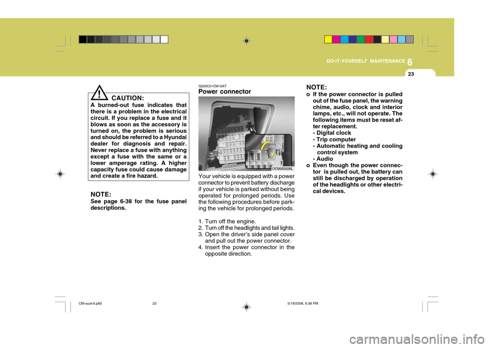
Your vehicle is equipped with a power connector to prevent battery discharge if your vehicle is parked without beingoperated for prolonged periods. Use the following procedures before park- ing the vehicle for prolonged periods.
1. Turn off the engine.
2. Turn off the headlights and tail lights.
3. Open the driver’s side panel cover and pull out the power connector.
4. Insert the power connector in the opposite direction.
OCM055026L
CM-aust-6.p65 5/19/2008, 6:38 PM
23
Page 232 of 269
6
DO-IT-YOURSELF MAINTENANCE
25
!
G210B01Y-GAT
Checking the Battery
Keep the battery clean. Any evidence of corrosion around the battery posts or terminals should be removed using a solution of household baking sodaand warm water. After the battery ter- minals are dry, cover them with a light coating of grease.
WARNING: Always read the following instructions carefully when handling a battery. Keep lighted cigarettes and all other flames or sparks away from the battery.Hydrogen, which is a highlycombustible gas, is alwayspresent in battery cells and may explode if ignited. Keep batteries out of the reach of children because batteries contain highly cor- rosive SULFURIC ACID. Do not allow battery acid tocontact your skin, eyes,clothing or paint finish.If any electrolyte gets intoyour eyes, flush your eyeswith clean water for at least 15 minutes and get imme- diate medical attention. Ifpossible, continue to apply water with a sponge or cloth until medical atten-tion is received.If electrolyte gets on yourskin, thoroughly wash the contacted area. If you feel a pain or a burn- ing sensation, get medical attention immediately. Wear eye protection when charging or working near a battery. Always provide ventilation when working in an en- closed space.
o When lifting a plastic-cased bat-
tery, excessive pressure on the case may cause battery acid to leak, resulting in personal injury. Lift with a battery carrier or withyour hands on opposite corners.
o Never attempt to charge the bat-
tery when the battery cables are connected.
o The electrical ignition system works with high voltage. Never touch these componentswith the engine running or the ignition switched on.
CM-aust-6.p65 5/19/2008, 6:38 PM
25
Page 235 of 269
6DO-IT-YOURSELF MAINTENANCE
28
OCM055007L
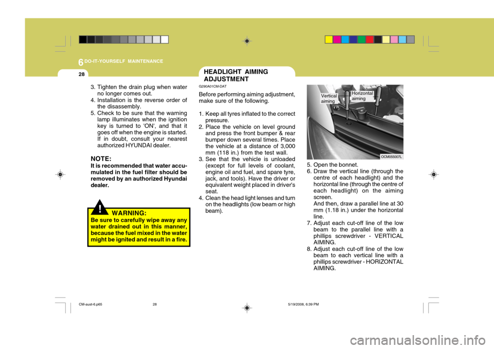
5. Open the bonnet.
6. Draw the vertical line (through the centre of each headlight) and thehorizontal line (through the centre of each headlight) on the aiming screen.And then, draw a parallel line at 30mm (1.18 in.) under the horizontalline.
7. Adjust each cut-off line of the low
beam to the parallel line with aphillips screwdriver - VERTICAL AIMING.
8. Adjust each cut-off line of the low beam to each vertical line with a phillips screwdriver - HORIZONTALAIMING.
Vertical aimingHorizontal aiming
HEADLIGHT AIMING ADJUSTMENT
G290A01CM-DAT Before performing aiming adjustment, make sure of the following.
1. Keep all tyres inflated to the correct pressure.
2. Place the vehicle on level ground and press the front bumper & rear bumper down several times. Placethe vehicle at a distance of 3,000 mm (118 in.) from the test wall.
3. See that the vehicle is unloaded (except for full levels of coolant, engine oil and fuel, and spare tyre,jack, and tools). Have the driver or equivalent weight placed in driver's seat.
4. Clean the head light lenses and turn on the headlights (low beam or highbeam).
!WARNING:
Be sure to carefully wipe away any water drained out in this manner, because the fuel mixed in the watermight be ignited and result in a fire.
3. Tighten the drain plug when water
no longer comes out.
4. Installation is the reverse order of the disassembly.
5. Check to be sure that the warning lamp illuminates when the ignitionkey is turned to 'ON', and that itgoes off when the engine is started.If in doubt, consult your nearestauthorized HYUNDAI dealer.
NOTE: It is recommended that water accu- mulated in the fuel filter should be removed by an authorized Hyundai dealer.
CM-aust-6.p65 5/19/2008, 6:39 PM
28
Page 238 of 269
6
DO-IT-YOURSELF MAINTENANCE
31
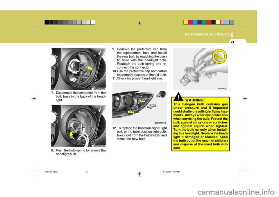
8. Push the bulb spring to remove the headlight bulb.
7. Disconnect the connector from the
bulb base in the back of the head- light.
OCM055011L
OCM055012L 9. Remove the protective cap from
the replacement bulb and install the new bulb by matching the plas- tic base with the headlight hole. Reattach the bulb spring and re-connect the connector.
10. Use the protective cap and carton
to promptly dispose of the old bulb.
11. Check for proper headlight aim.
OCM055014L
12. To replace the front turn signal light bulb or the front position light bulb, take it out from the bulb holder andinstall the new bulb.
!WARNING:
This halogen bulb contains gas
under pressure and if impacted could shatter, resulting in flying frag-ments. Always wear eye protection when servicing the bulb. Protect the bulb against abrasions or scratchesand against liquids when lighted. Turn the bulb on only when install- ing in a headlight. Replace the head-light if damaged or cracked. Keep the bulb out of the reach of children and dispose of the used bulb withcare.
G270A03O
CM-aust-6.p65 5/19/2008, 6:39 PM
31
Page 244 of 269
6
DO-IT-YOURSELF MAINTENANCE
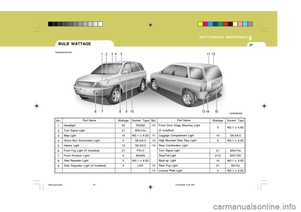
37BULB WATTAGE
G280A02CM-DAT
OCM058025A
Wattage5
10 5
21
21/5
16 215
Socket Type
PX26D
BAU15s
W2.1 x 9.5D
S8.5/8.5S8.5/8.5PG13
BAX9S
W2.1 x 9.5D LED Socket Type
W2.1 x 4.6D
S8.5/8.5
W2.1 x 9.5D
BAU15s
BAY15D
W2.1 x 9.5D BA15s
W2.1 x 9.5D
10 11 12 13 14 15
Part Name
Headlight Turn Signal Light Map Light Glove Box Illuminated Light Interior Light Front Fog Light (If Installed)
Front Position LightSide Repeater Light Side Repeater Light (if installed) Wattage
5521 10
5
10 27 65 5 No.No.
1 2 3 4 5 6 7 8 9Part Name
Front Door Edge Warning Light (if installed) Luggage Compartment Light High Mounted Rear Stop Light Rear Combination Light Turn Signal Light Stop/Tail Light Back-up Light Rear Fog Light License Plate Light
CM-aust-6.p65 5/19/2008, 6:40 PM
37
Page 266 of 269
3
10
INDEX
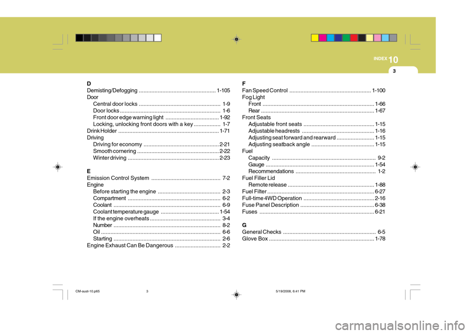
D Demisting/Defogging
................................................. 1-105
Door Central door locks .................................................... 1-9
Door locks ................................................................ 1-6
Front door edge warning light ..................................1-92
Locking, unlocking front doors with a key ................. 1-7
Drink Holder ................................................................ 1-71
Driving Driving for economy ................................................ 2-21
Smooth cornering .................................................... 2-22
Winter driving .......................................................... 2-23
EEmission Control System ............................................ 7-2
Engine Before starting the engine ........................................ 2-3Compartment ........................................................... 6-2
Coolant .................................................................... 6-9
Coolant temperature gauge .....................................1-54
If the engine overheats ............................................. 3-4
Number .................................................................... 8-2
Oil ............................................................................ 6-6Starting .................................................................... 2-6
Engine Exhaust Can Be Dangerous ............................. 2-2FFan Speed
Control .................................................... 1-100
Fog Light Front ....................................................................... 1-66
Rear ........................................................................ 1-67
Front Seats Adjustable front seats ............................................. 1-15
Adjustable headrests .............................................. 1-16
Adjusting seat forward and rearward ........................ 1-15
Adjusting seatback angle .. ......................................1-15
Fuel Capacity .................................................................. 9-2
Gauge ..................................................................... 1-54
Recommendations ................................................... 1-2
Fuel Filler Lid Remote release ....................................................... 1-88
Fuel Filter .................................................................... 6-27
Full-time 4 WD Operation ............................................. 2-16
Fuse Panel Description ............................................... 6-38
Fuses ......................................................................... 6-21
GGeneral Checks ........................................................... 6-5
Glove Box ................................................................... 1-78
CM-aust-10.p65 5/19/2008, 6:41 PM
3
Page 267 of 269
4
10INDEX
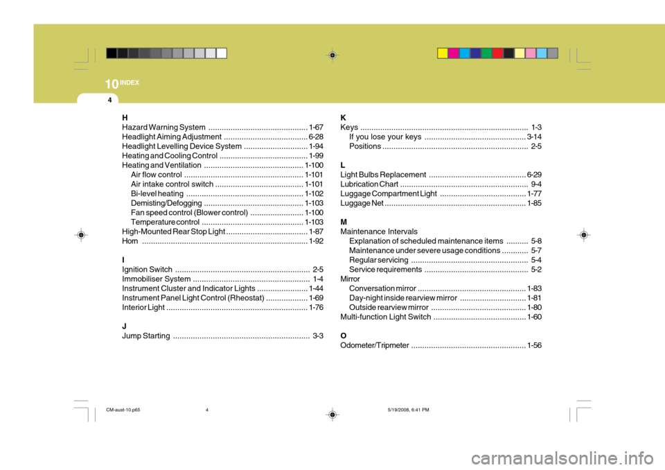
H Hazard Warning
System ............................................. 1-67
Headlight Aiming Adjustment ......................................6-28
Headlight Levelling Device System .............................1-94
Heating and Cooling Con trol ........................................ 1-99
Heating and Ventilation ............................................. 1-100
Air flow control ...................................................... 1-101
Air intake control switch ........................................ 1-101
Bi-level heating ..................................................... 1-102
Demisting/Defogging ............................................. 1-103
Fan speed control (Blower control) ........................1-100
Temperature control .............................................. 1-103
High-Mounted Rear Stop Light ..................................... 1-87
Horn ........................................................................... 1-92
IIgnition Switch ............................................................. 2-5
Immobiliser System ..................................................... 1-4
Instrument Cluster and Indicator Lights .......................1-44
Instrument Panel Light Control (Rheostat) ................... 1-69
Interior Light ................................................................ 1-76
JJump Starting .............................................................. 3-3 KKeys
............................................................................ 1-3
If you lose y our keys .............................................. 3-14
Positions .................................................................. 2-5
LLight Bulbs R eplacement............................................ 6-29
Lubrication Chart .......................................................... 9-4
Luggage Compartment Light .......................................1-77
Luggage Net ................................................................ 1-85
MMaintenance Intervals Explanation of scheduled maintenance items .......... 5-8Maintenance under severe usage conditions ............ 5-7
Regular servi cing..................................................... 5-4
Service requ irements............................................... 5-2
Mirror Conversation mirror ................................................. 1-83
Day-night inside rearview mirror .............................. 1-81
Outside rearview mirror ........................................... 1-80
Multi-function Light Switch ................... .......................1-60
OOdometer/Tripmeter .................................................... 1-56
CM-aust-10.p65 5/19/2008, 6:41 PM
4
Page 269 of 269
6
10INDEX
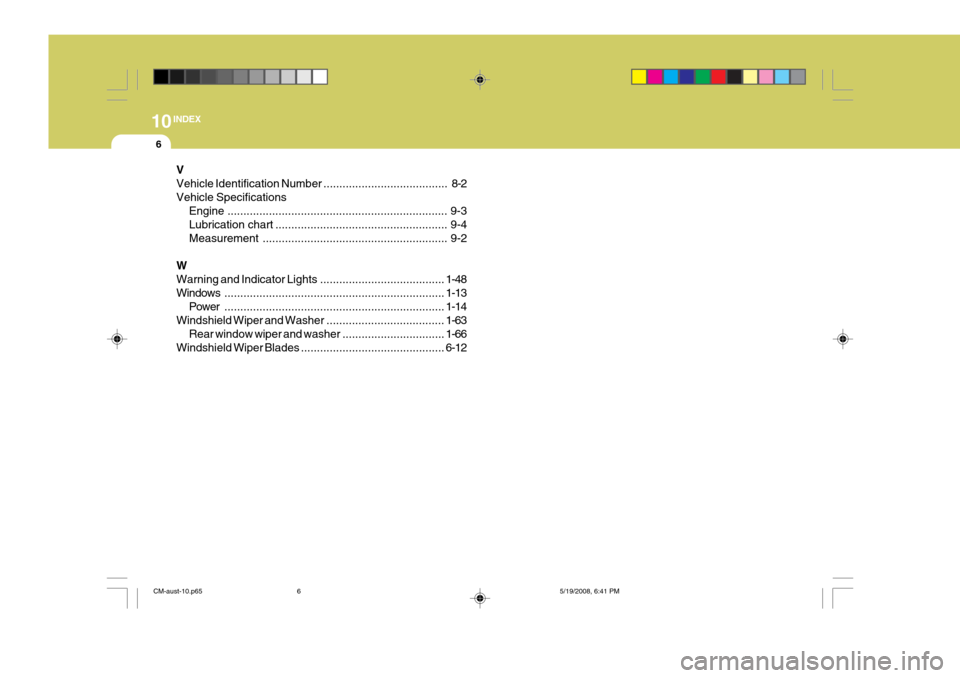
V
Vehicle Identification Number ..............
......................... 8-2
Vehicle Specifications Engine ..................................................................... 9-3
Lubrication chart ...................................................... 9-4
Measurement .......................................................... 9-2
WWarning and Indicator Lights .......................................1-48
Windows ..................................................................... 1-13
Power ..................................................................... 1-14
Windshield Wiper and Was her ..................................... 1-63
Rear window wiper and washer ................................1-66
Windshield Wiper Blad es ............................................. 6-12
CM-aust-10.p65 5/19/2008, 6:41 PM
6