2009 Hyundai Getz coolant temperature
[x] Cancel search: coolant temperaturePage 149 of 191

DO-IT-YOURSELF MAINTENANCE 6- 7
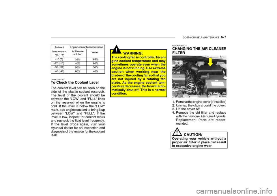
G050C02A-DAT To Check the Coolant Level The coolant level can be seen on the side of the plastic coolant reservoir.The level of the coolant should be between the "LOW" and "FULL" lines on the reservoir when the engine is cold. If the level is below the "LOW" mark, add engine coolant to bring it upbetween "LOW" and "FULL". If the level is low, inspect for coolant leaks and recheck the fluid level frequently.If the level drops again, visit your Hyundai dealer for an inspection and diagnosis of the reason for the coolantleak.
35% 40%50%60%
Ambient
temperature °C ( °F)-15 (5)
-25 (-13)-35 (-31)-45 (-49)
Antifreeze solution Water
Engine coolant concentration
65% 60%50%40%
!WARNING:
The cooling fan is controlled by en- gine coolant temperature and may sometimes operate even when the engine is not running. Use extremecaution when working near the blades of the cooling fan so that you are not injured by a rotating fanblade. As the engine coolant tem- perature decreases, the fan will auto- matically shut off. This is a normalcondition.
HTB168
G070A01TB-AAT CHANGING THE AIR CLEANER FILTER
1. Remove the engine cover (If installed)
2. Unsnap the clips around the cover.
3. Lift the cover off.
4. Remove the old filter and replace
with the new one. Genuine Hyundai Replacement Parts are recom- mended.
CAUTION:
Operating your vehicle without aproper air filter in place can result in excessive engine wear.
!
Page 154 of 191

6- 12 DO-IT-YOURSELF MAINTENANCE
!
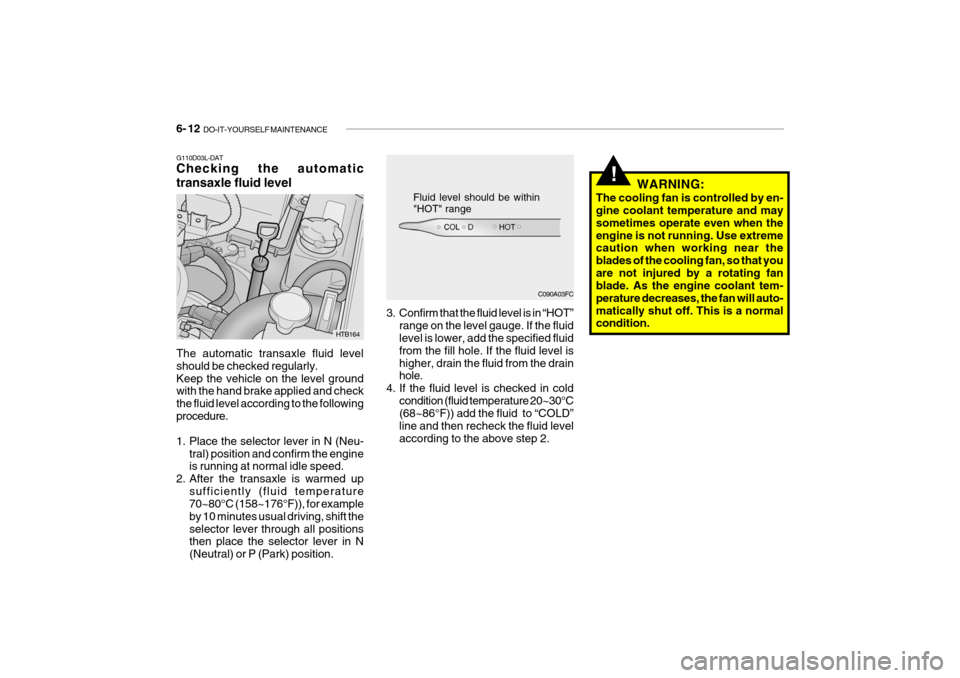
G110D03L-DAT Checking the automatic transaxle fluid level The automatic transaxle fluid level should be checked regularly.Keep the vehicle on the level ground with the hand brake applied and check the fluid level according to the followingprocedure.
1. Place the selector lever in N (Neu-
tral) position and confirm the engine is running at normal idle speed.
2. After the transaxle is warmed up sufficiently (fluid temperature70~80°C (158~176°F)), for example by 10 minutes usual driving, shift theselector lever through all positions then place the selector lever in N (Neutral) or P (Park) position. C090A03FC
Fluid level should be within "HOT" range
HTB164 3. Confirm that the fluid level is in “HOT”
range on the level gauge. If the fluid level is lower, add the specified fluid from the fill hole. If the fluid level ishigher, drain the fluid from the drain hole.
4. If the fluid level is checked in cold
condition (fluid temperature 20~30°C(68~86°F)) add the fluid to “COLD” line and then recheck the fluid levelaccording to the above step 2. WARNING:
The cooling fan is controlled by en- gine coolant temperature and may sometimes operate even when theengine is not running. Use extreme caution when working near the blades of the cooling fan, so that youare not injured by a rotating fan blade. As the engine coolant tem- perature decreases, the fan will auto-matically shut off. This is a normal condition.
Page 164 of 191

6- 22 DO-IT-YOURSELF MAINTENANCE
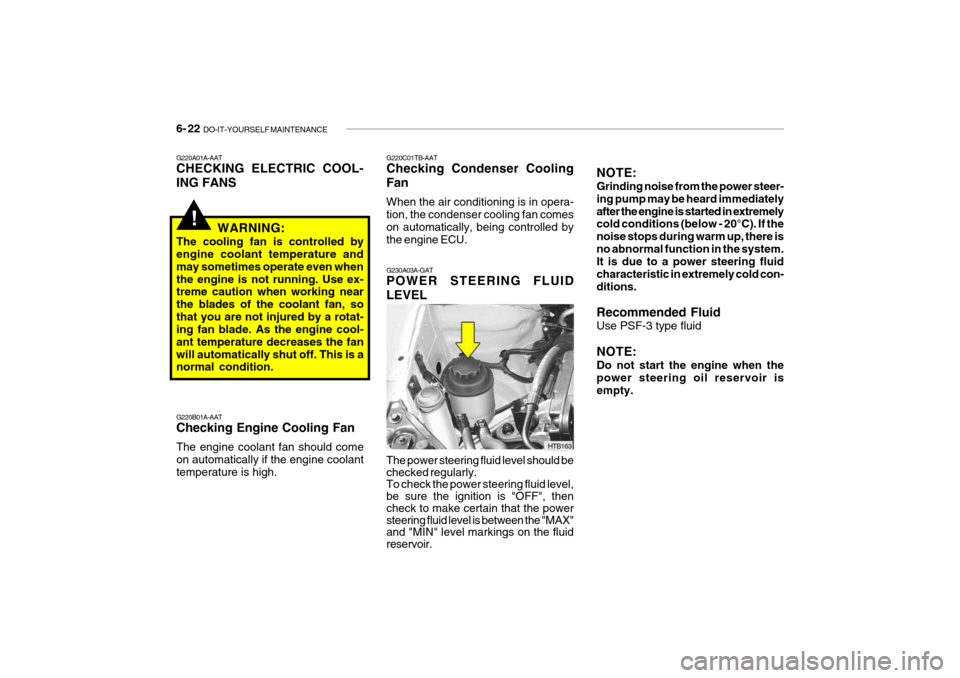
G230A03A-GAT POWER STEERING FLUID LEVEL The power steering fluid level should be checked regularly. To check the power steering fluid level, be sure the ignition is "OFF", then check to make certain that the power steering fluid level is between the "MAX" and "MIN" level markings on the fluid reservoir. HTB163NOTE: Grinding noise from the power steer- ing pump may be heard immediatelyafter the engine is started in extremely cold conditions (below - 20°C). If the noise stops during warm up, there isno abnormal function in the system. It is due to a power steering fluid characteristic in extremely cold con-ditions. Recommended Fluid Use PSF-3 type fluid NOTE: Do not start the engine when the power steering oil reservoir is empty.
!
G220A01A-AAT CHECKING ELECTRIC COOL- ING FANS
WARNING:
The cooling fan is controlled by engine coolant temperature and may sometimes operate even whenthe engine is not running. Use ex- treme caution when working near the blades of the coolant fan, sothat you are not injured by a rotat- ing fan blade. As the engine cool- ant temperature decreases the fanwill automatically shut off. This is a normal condition. G220B01A-AAT Checking Engine Cooling Fan The engine coolant fan should come on automatically if the engine coolanttemperature is high. G220C01TB-AAT Checking Condenser Cooling Fan When the air conditioning is in opera- tion, the condenser cooling fan comes on automatically, being controlled by
the engine ECU.
Page 175 of 191

7- 2 EMISSION CONTROL SYSTEMS
H010A01A-DAT
EMISSION CONTROL SYSTEM (If Installed)
Your Hyundai is equipped with an
emission control system to meet all ADR requirements. There are three emission control sys-
tems which are as follows.
1. Crankcase emission control sys- tem
2. Evaporative emission control sys- tem
3. Exhaust emission control system
In order to assure the proper function
of the emission control systems, it is recommended that you have your car inspected and maintained by anauthorised Hyundai dealer in accor- dance with the maintenance sched- ule in this manual. H010B01A-AAT
1. Crankcase Emission Control
System
The positive crankcase ventilation
system is employed to prevent airpollution caused by blow-by gases being emitted from the crankcase. This system supplies fresh air to thecrankcase through the air intake hose. Inside the crankcase, the fresh air mixes with blow-by gases, which thenpass through the PCV valve and into the induction system.
H010C01A-DAT
2. Evaporative Emission
Control System (If Installed)
The Evaporative Emission Control
System is designed to prevent fuel vapors from escaping into the atmo- sphere. H010D01A-DAT
3. Exhaust Emission Control
System
This system has been integrated intoa highly effective system which con- trols exhaust emissions while main-taining good vehicle performance.
Canister
While the engine is inoperative, fuel
vapors generated inside the fuel tankare absorbed and stored in the canis-ter. When the engine is running, the fuel vapors absorbed in the canister are drawn into the induction systemthrough the purge control solenoid valve. Purge Control Solenoid Valve
The purge control solenoid valve is
controlled by the ECU; when the en- gine coolant temperature is low, and during idling, it closes, so that evapo- rated fuel is not taken into the engine.After engine warm-up, during ordi- nary driving, it opens so as to intro- duce evaporated fuel to the engine.
Page 189 of 191

INDEX 10- 3
Drink Holder ................................................................ 1-54
Drive Belts .................................................................. 6-18
Driving Economical driving .................................................. 2-14
Smooth corneri ng ..................................................... 2-15
Winter driving ........................................................... 2-15
E Emission Contro l System ............................................ 7-2
Engine Before starting the engine ........................................ 2-3Compartment ............................................................ 6-2
Coolant ..................................................................... 6-6
Coolant temperature Indicator ..................................1-41
If the engine overheats ............................................. 3-4
Number ..................................................................... 8-2
Oil ............................................................................. 6-4Starting ..................................................................... 2-4
Engine Exhaust Can Be Dangerous ............................ 2-2
F
Fan Speed Control ...................................................... 1-72
Fog Light
Front ........................................................................ 1-51
Front Seats Adjustable front seats .............................................. 1-12Adjustable headrests
............................................... 1-13
Adjusting seat forward and rearward ........................1-12
Adjusting seatback angle .. ......................................1-12
Lumbar support control ............................................ 1-14
Seat cushion height adjustment .............................. 1-14
Fuel
Capacity ................................................................... 9-2
Gauge ...................................................................... 1-41
recommendations ...................................................... 1-2
Fuel Filler Lid Remote release ....................................................... 1-63
Fuses ......................................................................... 6-18
Fuse panel Description ............................................... 6-30
GGeneral Checks ........................................................... 6-4
Glove Box .................................................................. 1-58
H Hand Brake ................................................................. 1-61
Hazard Warning System ............................................. 1-50
Headlight Aiming Adjustment...................................... 6-23
Heating and Cooling Control .......................................1-71
Air flow control ......................................................... 1-73
Air intake control ..................................................... 1-73
Bi-level heati ng ........................................................ 1-76
Fan speed control .................................................... 1-72
Temperature control ................................................. 1-75