Page 255 of 308

Maintenance
30
7
Battery recharging
Your vehicle has a maintenance-free,
calcium-based battery.
If the battery becomes discharged in a
short time (because, for example, the
headlights or interior lights were left on
while the vehicle was not in use),
recharge it by slow charging (trickle)
for 10 hours.
If the battery gradually discharges because of high electric load while the
vehicle is being used, recharge it at 20-
30A for two hours. Reset items
Items should be reset after the battery
has been discharged or the battery hasbeen disconnected.
Sunroof (See Chapter 4)
Trip computer (See Chapter 4)
Climate control system
(See Chapter 4)
Clock (See Chapter 4)
Audio (See Chapter 4)
Auto up/down window (See chapter 4)(Continued)
When lifting a plastic-cased bat- tery, excessive pressure on the
case may cause battery acid to
leak, resulting in personal injury.
Lift with a battery carrier or with
your hands on opposite corners.
Never attempt to recharge the battery when the battery cablesare connected.
The electrical ignition system works with high voltage. Never
touch these components with theengine running or the ignition
switched on.
Failure to follow the above warn-
ings can result in serious bodily
injury or death.
Page 256 of 308

731
Maintenance
WARNING- Recharging
battery
When recharging the battery,
observe the following precautions:
The battery must be removed from the vehicle and placed in an area with good ventilation.
Do not allow cigarettes, sparks, or flame near the battery.
Watch the battery during charg- ing, and stop or reduce the charg-
ing rate if the battery cells begin
gassing (boiling) violently or if
the temperature of the electrolyte
of any cell exceeds 49°C (120°F).
Wear eye protection when check- ing the battery during charging.
(Continued)(Continued)
Disconnect the battery charger inthe following order.
1. Turn off the battery charger main switch.
2. Unhook the negative clamp from the negative battery terminal.
3. Unhook the positive clamp from the positive battery terminal.WARNING
Before performing maintenance or recharging the battery, turn off all accessories and stop the
engine.
The negative battery cable must be removed first and installed
last when the battery is discon-nected.
Page 266 of 308

741
Maintenance
FUSES
A vehicle’s electrical system is protected
from electrical overload damage by
fuses. This vehicle has 2 (or 3) fuse panels, one
located in the driver’s side panel bolster,
the other in the engine compartment
near the battery.
If any of your vehicle’s lights, acces-
sories, or controls do not work, check the
appropriate circuit fuse. If a fuse has
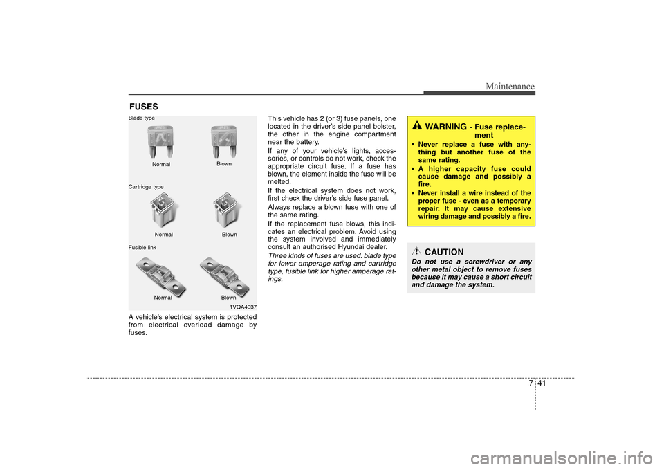
blown, the element inside the fuse will bemelted.
If the electrical system does not work,
first check the driver’s side fuse panel.
Always replace a blown fuse with one of
the same rating.
If the replacement fuse blows, this indi-
cates an electrical problem. Avoid using
the system involved and immediately
consult an authorised Hyundai dealer.
Three kinds of fuses are used: blade type
for lower amperage rating and cartridge
type, fusible link for higher amperage rat-ings.
1VQA4037
Normal
Normal
Blade type
Cartridge type
Fusible link Blown
Blown
Normal Blown
WARNING - Fuse replace-
ment
Never replace a fuse with any- thing but another fuse of the same rating.
A higher capacity fuse could cause damage and possibly a
fire.
Never install a wire instead of the proper fuse - even as a temporary
repair. It may cause extensive
wiring damage and possibly a fire.
CAUTION
Do not use a screwdriver or any
other metal object to remove fuses because it may cause a short circuit
and damage the system.
Page 267 of 308
Maintenance
42
7
Inner panel fuse replacement
1. Turn the ignition switch and all other
switches off.
2. Open the fuse panel cover. 3. Pull the suspected fuse straight out.
Use the removal tool provided on the
main fuse box in the engine compart-ment.
4. Check the removed fuse; replace it if it is blown.
5. Push in a new fuse of the same rating, and make sure it fits tightly in the clips.
If it fits loosely, consult an authorised
Hyundai dealer.
If you do not have a spare, use a fuse of the same rating from a circuit you may
not need for operating the vehicle, such as the cigar lighter fuse.
If the headlights or other electrical com-
ponents do not work and the fuses are
OK, check the fuse block in the engine
compartment. If a fuse is blown, it mustbe replaced.
OHD076025R
Driver’s side panel
OHD076026
Page 268 of 308
743
Maintenance
Memory fuse
Your vehicle is equipped with the memo-
ry fuse to prevent battery discharge if
your vehicle is parked without being
operated for prolonged periods. Use the
following procedures before parking the
vehicle for prolonged periods.
1. Turn off the engine.
2. Turn off the headlights and tail lights.
3. Open the driver’s side panel cover andpull up the memory fuse.
✽✽ NOTICE
Page 269 of 308
Maintenance
44
7
Main fuse
If the main fuse is blown, it must be
removed as follows:
1. Disconnect the negative battery cable.
2. Remove the nuts shown in the picture
above.
3. Replace the fuse with a new one of the same rating.
4. Reinstall in the reverse order of removal. ✽
✽
NOTICE
If the main fuse is blown, consult an
Authorised Hyundai Dealer.CAUTION
After checking the fuse box in the
engine compartment, securelyinstall the fuse box cover. If not, electrical failures may occur from
water leaking in.
OHD076030
Page 270 of 308
745
Maintenance
✽✽NOTICE
Not all fuse panel descriptions in this
manual may be applicable to your vehi-cle. It is accurate at the time of printing.When you inspect the fuse box on your
vehicle, refer to the fuse box label.
Engine compartment
OHD076031R/OHD076032
Fuse/Relay panel description
Inside the fuse/relay box covers, you can find the fuse/relay label describing fuse/relay
name and capacity.
Driver’s side panel
Page 273 of 308

Maintenance
48
7
Engine compartment
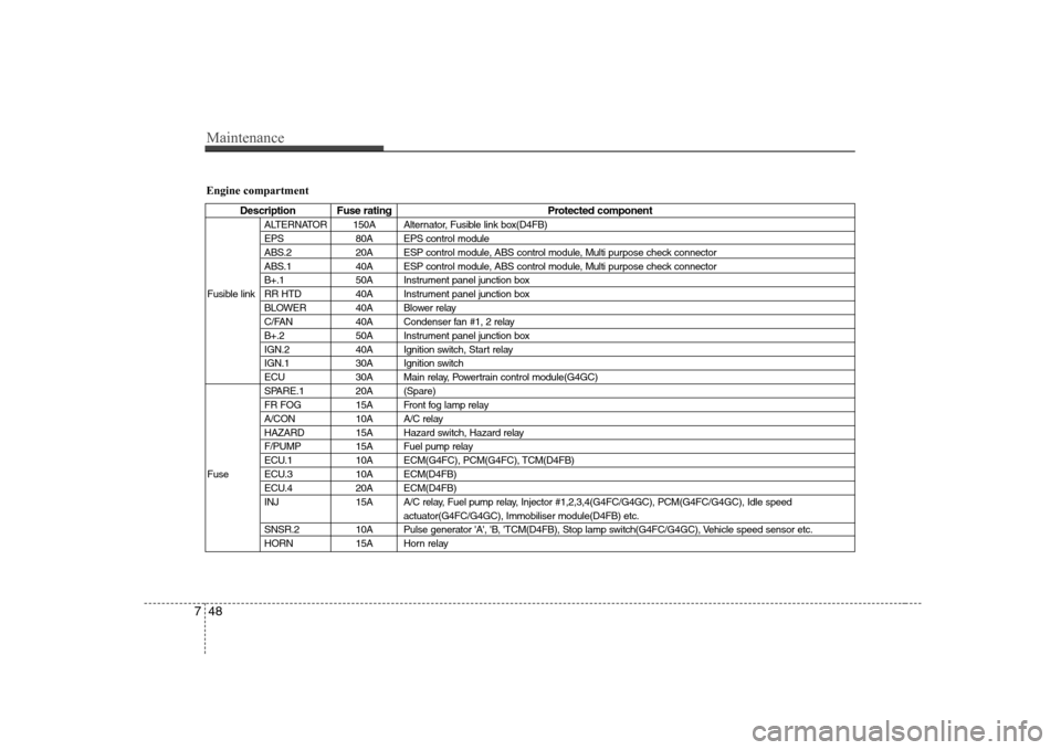
Description Fuse rating Protected component
ALTERNATOR 150A Alternator, Fusible link box(D4FB)
EPS 80A EPS control module
ABS.2 20A ESP control module, ABS control module, Multi purpose check connector
ABS.1 40A ESP control module, ABS control module, Multi purpose check connector
B+.1 50A Instrument panel junction box
Fusible link RR HTD 40A Instrument panel junction box BLOWER 40A Blower relay
C/FAN 40A Condenser fan #1, 2 relay
B+.2 50A Instrument panel junction box
IGN.2 40A Ignition switch, Start relay
IGN.1 30A Ignition switch
ECU 30A Main relay, Powertrain control module(G4GC)
SPARE.1 20A (Spare)
FR FOG 15A Front fog lamp relay
A/CON 10A A/C relay
HAZARD 15A Hazard switch, Hazard relay
F/PUMP 15A Fuel pump relay
ECU.1 10A ECM(G4FC), PCM(G4FC), TCM(D4FB)
Fuse ECU.3 10A ECM(D4FB) ECU.4 20A ECM(D4FB)
INJ 15A A/C relay, Fuel pump relay, Injector #1,2,3,4(G4FC/G4GC), PCM(G4FC/G4GC), Idle speed actuator(G4FC/G4GC), Immobiliser module(D4FB) etc.
SNSR.2 10A Pulse generator 'A', 'B, 'TCM(D4FB), Stop lamp switch(G4FC/G4GC), Vehicle speed sensor etc.
HORN 15A Horn relay