2009 Hyundai Accent check engine
[x] Cancel search: check enginePage 202 of 232
6
DO-IT-YOURSELF MAINTENANCE
21
!
G220B01A-AAT Checking Engine Cooling Fan The engine coolant fan should come on automatically if the engine coolanttemperature is high. G220C01TB-GAT Checking Condenser Cooling Fan When the air conditioning is in opera- tion, the condenser cooling fan comeson automatically, being controlled by
the engine ECU.
WARNING:
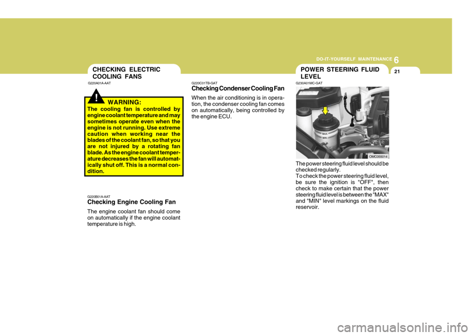
The cooling fan is controlled by engine coolant temperature and may sometimes operate even when the engine is not running. Use extremecaution when working near the blades of the coolant fan, so that you are not injured by a rotating fanblade. As the engine coolant temper- ature decreases the fan will automat- ically shut off. This is a normal con-dition. The power steering fluid level should be checked regularly. To check the power steering fluid level,be sure the ignition is "OFF", then check to make certain that the power steering fluid level is between the "MAX"and "MIN" level markings on the fluid reservoir.
CHECKING ELECTRIC COOLING FANS
G220A01A-AATPOWER STEERING FLUID LEVEL
G230A01MC-GAT
OMC055014
Page 203 of 232
6 DO-IT-YOURSELF MAINTENANCE
22HEADLIGHT AIMING ADJUSTMENT
G290A03A-DAT Before performing aiming adjustment, make sure of the following.
1. Keep all tyres inflated to the correct
pressure.
2. Place the vehicle on level ground and press the front bumper & rear bumper down several times. Placethe vehicle at a distance of 3,000 mm (118 in.) from the test wall.
3. See that the vehicle is unloaded (except for full levels of coolant,engine oil and fuel, and spare tyre, jack, and tools).Have the driver or equivalent weight placed in driver's seat.
4. Clean the head light lenses and turn on the headlights (low beam).
NOTE:
o Grinding noise from the power
steering pump may be heard im- mediately after the engine is startedin extremely cold conditions (be- low - 20°C). If the noise stops during warm up, there is no ab-normal function in the system. It is due to a power steering fluid characteristic in extremely coldconditions.
o Do not start the engine when the
power steering oil reservoir isempty. G240A01A-DAT POWER STEERING HOSES It is suggested that you check the power steering hose connections forfluid leakage at those intervals speci- fied in the vehicle maintenance sched- ule in Section 5. The power steeringhoses should be replaced if there is severe surface cracking, pulling, scuff- ing or worn spots. Deterioration of thehoses could cause premature failure.
Page 205 of 232
6 DO-IT-YOURSELF MAINTENANCE
24
Headlight
1. Allow the bulb to cool. Wear eye protection.
2. Open the engine bonnet and discon- nect the negative (-) post of the battery.
3. Always grasp the bulb by its plastic base, avoid touching the glass.
4. Disconnect the power cord from the
back of the headlight.
o After heavy, driving rain or wash-ing, headlight and taillight lenses could appear frosty. This condi-tion is caused by the temperature difference between the lamp in- side and outside. This is similarto the condensation on your win- dows inside your vehicle during the rain and doesn’t indicate aproblem with your vehicle. If the water leaks into the lamp bulb circuitry, have the vehicle checkedby an authorised Hyundai dealer.
REPLACEMENT OF LIGHT BULBS
G260A01MC-DAT Before attempting to replace a light bulb, be sure the switch is turned to the "OFF" position. The next paragraph shows how to reachthe light bulbs so they may be changed. Be sure to replace the burned-out bulb with one of the same number and watt-age rating. All bulbs are available from your Hyundai dealers Parts Department. See page 6-29 for the wattage descrip-tions.
CAUTION:
o Keep the lamps out of contact with petroleum products, such as oil, petrol, etc.
o If you don't have necessary tools, the correct bulbs and the exper-tise, consult your authorised Hyundai dealer.
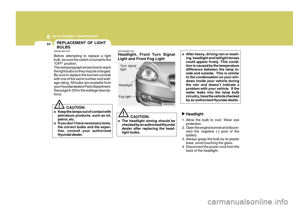
! G270A02MC-DAT Headlight, Front Turn Signal Light and Front Fog Light
CAUTION:
o The headlight aiming should be checked by an authorised Hyundai dealer after replacing the head- light bulbs.
!
OMC055021
Turn signal light
Headlight Fog light
Page 206 of 232
6
DO-IT-YOURSELF MAINTENANCE
25
Front Turn Signal light
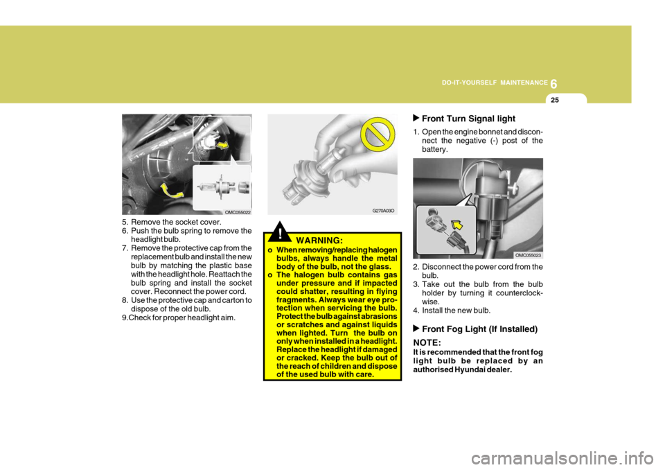
1. Open the engine bonnet and discon- nect the negative (-) post of the battery.
2. Disconnect the power cord from the bulb.
3. Take out the bulb from the bulb holder by turning it counterclock-wise.
4. Install the new bulb.
G270A03O
!WARNING:
o When removing/replacing halogen bulbs, always handle the metal body of the bulb, not the glass.
o The halogen bulb contains gas
under pressure and if impacted could shatter, resulting in flying fragments. Always wear eye pro- tection when servicing the bulb. Protect the bulb against abrasions or scratches and against liquids when lighted. Turn the bulb on only when installed in a headlight. Replace the headlight if damaged or cracked. Keep the bulb out of the reach of children and dispose of the used bulb with care.
5. Remove the socket cover.
6. Push the bulb spring to remove the
headlight bulb.
7. Remove the protective cap from the replacement bulb and install the new bulb by matching the plastic base with the headlight hole. Reattach thebulb spring and install the socket cover. Reconnect the power cord.
8. Use the protective cap and carton to dispose of the old bulb.
9.Check for proper headlight aim.
OMC055022
OMC055023
Front Fog Light (If Installed)
NOTE: It is recommended that the front fog light bulb be replaced by anauthorised Hyundai dealer.
Page 211 of 232
6 DO-IT-YOURSELF MAINTENANCE
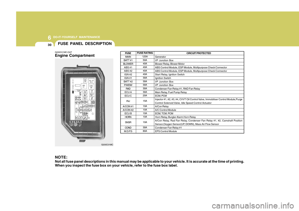
30FUSE PANEL DESCRIPTION
G200C01MC-DAT Engine Compartment NOTE: Not all fuse panel descriptions in this manual may be applicable to your vehicle. It is accurate at the time of printing. When you inspect the fuse box on your vehicle, refer to the fuse box label.
G200C01MC FUSE RATING
125A50A 40A 40A 40A40A 30A 30A30A 30A 30A20A 15A10A 10A 10A10A 10A30A 80A CIRCUIT PROTECTED
GeneratorI/P Junction Box
Blower Relay, Blower MotorABS Control Module, ESP Module, Multipurpose Check Connector ABS Control Module, ESP Module, Multipurpose Check Connector
Start Relay, Ignition SwitchIgnition Switch I/P Junction Box I/P Junction BoxCondenser Fan Relay #1, RAD Fan Relay
Main Relay, Fuel Pump Relay ECM, PCM
Injector #1, #2, #3, #4, CVVT Oil Control Valve, Immobiliser Control Module,Purge
Control Solenoid Valve, Idle Speed Control Actuator A/Con RelayA/C Control ModuleECM, TCM, PCM
Horn Relay, Burglar Alarm Horn Relay
A/Con Relay, Rad Fan Relay, Condenser Fan Relay #1, #2, Camshaft Position
Sensor,Oxygen Sensor(UP, DOWN), Mass Air Flow Sensor Condenser Fan Relay #1 EPS Control Module
MAIN
BATT #1
BLOWER
ABS #1 ABS #2IGN #2 IGN #1
BATT #2 P/WDW
RAD
ECU A ECU C
INJ
A/CON #1 A/CON #2 ECU BHORN
SNSR
COND
M.D.P.S
FUSE
Page 230 of 232
10
INDEX
3
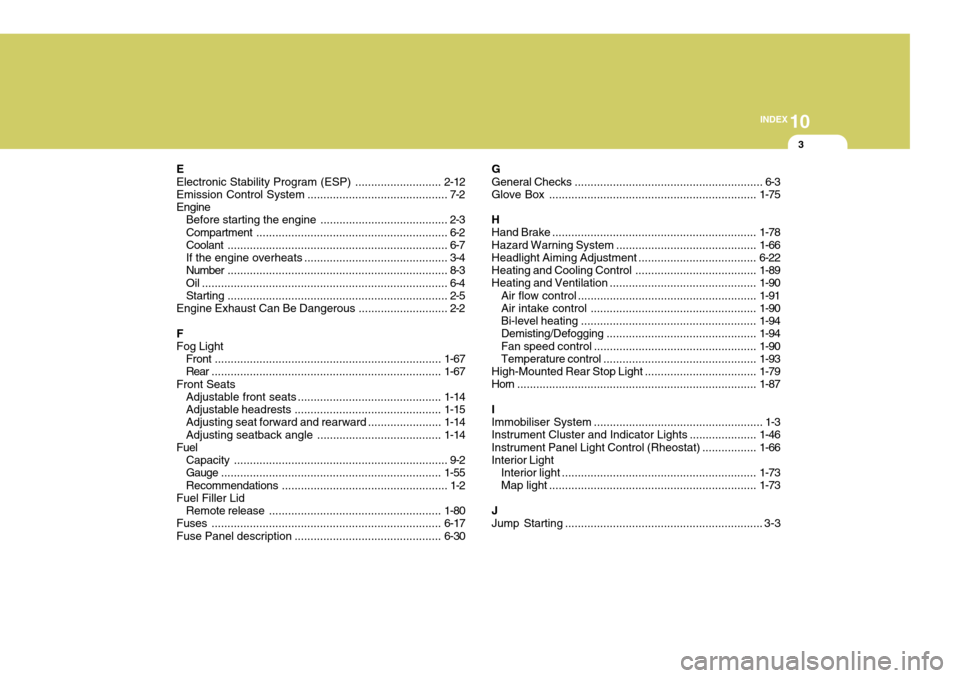
E Electronic Stability Program (ESP) ...........................2-12
Emission Contro l System ............................................ 7-2
Engine Before starting the engine ........................................ 2-3Compartment ............................................................ 6-2
Coolant ..................................................................... 6-7
If the engine overheats ............................................. 3-4
Number ..................................................................... 8-3
Oil ............................................................................. 6-4 Starting ..................................................................... 2-5
Engine Exhaust Can Be Dangerous ............................ 2-2
FFog Light Front ....................................................................... 1-67
Rear ........................................................................ 1-67
Front Seats Adjustable front seats ............................................. 1-14
Adjustable headrests .............................................. 1-15
Adjusting seat forward and rearward .......................1-14
Adjusting seatback angle ....................................... 1-14
Fuel
Capacity ................................................................... 9-2
Gauge ..................................................................... 1-55
Recommendations .................................................... 1-2
Fuel Filler Lid
Remote release ...................................................... 1-80
Fuses ........................................................................ 6-17
Fuse Panel description .............................................. 6-30G General Checks
........................................................... 6-3
Glove Box ................................................................. 1-75
H Hand Brake ................................................................ 1-78
Hazard Warning System ............................................ 1-66
Headlight Aiming Adjustment..................................... 6-22
Heating and Cooling Control ......................................1-89
Heating and Ventilation .............................................. 1-90
Air flow control ........................................................ 1-91
Air intake control .................................................... 1-90
Bi-level heati ng ....................................................... 1-94
Demisting/Defogging ............................................... 1-94
Fan speed control ................................................... 1-90
Temperature control ................................................ 1-93
High-Mounted Rear Stop Light................................... 1-79
Horn ........................................................................... 1-87
IImmobiliser System ..................................................... 1-3
Instrument Cluster and Indicator Lights ..................... 1-46
Instrument Panel Light Control (Rheostat) .................1-66
Interior Light
Interior light ............................................................. 1-73
Map light ................................................................. 1-73
JJump Starting .............................................................. 3-3