Page 474 of 532

CONT INUED
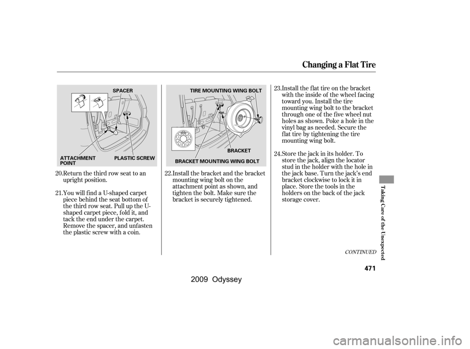
Install the bracket and the bracket
mountingwingboltonthe
attachment point as shown, and
tighten the bolt. Make sure the
bracket is securely tightened.Install the flat tire on the bracket
with the inside of the wheel facing
toward you. Install the tire
mounting wing bolt to the bracket
through one of the f ive wheel nut
holes as shown. Poke a hole in the
vinyl bag as needed. Secure the
f lat tire by tightening the tire
mounting wing bolt.
Store the jack in its holder. To
store the jack, align the locator
stud in the holder with the hole in
the jack base. Turn the jack’s end
bracket clockwise to lock it in
place. Store the tools in the
holders on the back of the jack
storage cover.
Return the third row seat to an
upright position.
YouwillfindaU-shapedcarpet
piece behind the seat bottom of
the third row seat. Pull up the U-
shaped carpet piece, f old it, and
tack the end under the carpet.
Remove the spacer, and unfasten
the plastic screw with a coin.
20.
21.
22.23.
24.
Changing a Flat Tire
T aking Care of t he Unexpect ed
471
BRACKET
TIRE MOUNTING WING BOLT
SPACER
PLASTIC SCREW BRACKET MOUNTING WING BOLT
ATTACHMENT
POINT
�\f���—�\f���—���
�y�
����
��������y���
�(���������\f�y�\f�������y
2009 Odyssey
Page 475 of 532

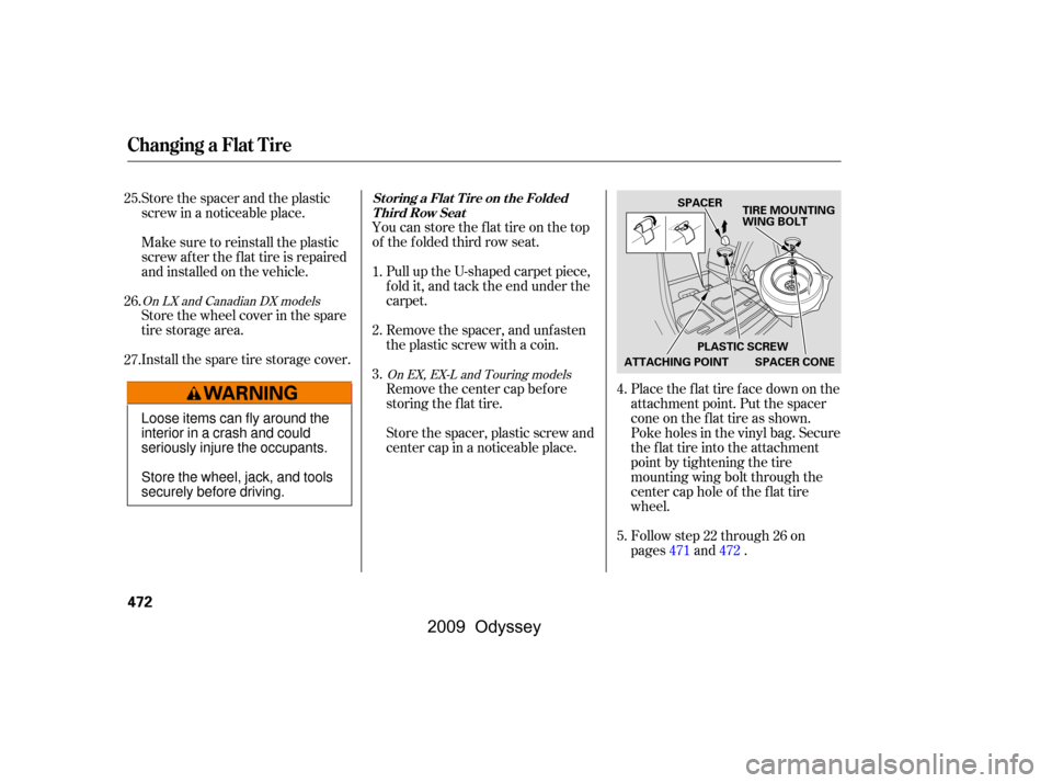
You can store the f lat tire on the top
of the f olded third row seat.
Pull up the U-shaped carpet piece,
f old it, and tack the end under the
carpet.
Remove the spacer, and unfasten
the plastic screw with a coin.
Place the flat tire face down on the
attachment point. Put the spacer
cone on the f lat tire as shown.
Poke holes in the vinyl bag. Secure
the flat tire into the attachment
point by tightening the tire
mounting wing bolt through the
center cap hole of the f lat tire
wheel.
Follow step 22 through 26 on
pages and .
Store the spacer and the plastic
screw in a noticeable place.
Make sure to reinstall the plastic
screw af ter the f lat tire is repaired
andinstalledonthevehicle.
Store the wheel cover in the spare
tire storage area.
Install the spare tire storage cover.
Remove the center cap before
storing the f lat tire.
Store the spacer, plastic screw and
center cap in a noticeable place.
1.
2.
3.
4.
5.
25.
26.
27.
471472
On EX, EX-L and Touring models
On LX and Canadian DX models
St oring a Flat T ire on t he Folded
Third Row Seat
Changing a Flat Tire
472
TIRE MOUNTING WING BOLT
ATTACHING POINT
SPACER
PLASTIC SCREW
SPACER CONE
Loose items can fly around the
interior in a crash and could
seriously injure the occupants.
Store the wheel, jack, and tools
securely before driving.
�����—�����—���
�y�
����
��������y���
�(�����������y���������y
2009 Odyssey
Page 484 of 532

The brake system
indicator normally
comesonwhenyou
turn the ignition switch to the ON
(II) position, and as a reminder to
check the parking brake. It will stay
on if you do not f ully release the
parking brake.
If the brake system indicator comes
on while driving, the brake f luid level
is probably low. Press lightly on the
brake pedal to see if it f eels normal.
If it does, check the brake f luid level
thenexttimeyoustopataservice
station (see page ). Slow down by shif ting to a lower
gear, and pull to the side of the road
when it is saf e. Because of the long
distance needed to stop, it is
hazardous to drive the vehicle. You
should have it towed and repaired as
soon as possible (see
on page ).
If the f luid level is low, take your
vehicle to a dealer, and have the
brake system inspected f or leaks or
worn brake pads.
However, if the brake pedal does not
f eel normal, you should take
immediate action. A problem in one
part of the system’s dual circuit
design will still give you braking at
two wheels. You will f eel the brake
pedal go down much f arther bef ore
the vehicle begins to slow down, and
you will have to press harder on the
pedal.
If the ABS indicator and the VSA
indicator come on with the brake
system indicator, have the vehicle
inspected by your dealer
immediately.
If you must drive the vehicle a short
distance in this condition, drive
slowly and caref ully.
You will also see a ‘‘CHECK BRAKE
SYSTEM’’ message on the multi-
inf ormation display (see page ).
You will also see a ‘‘BRAKE FLUID
LOW’’ message on the multi-
inf ormation display (see page ).
88 88
435 488
On Touring models
On Touring models
Brake System Indicator
Emergency
Towing
T aking Care of t he Unexpect ed
481
U.S. Canada
�\f���—�\f���—���
�y�
����
������
�y���
�(���������\f�y�\f�������y
2009 Odyssey
Page 491 of 532

�µ�µ
If your vehicle needs to be towed,
call a prof essional towing service or
organization. Never tow your vehicle
with just a rope or chain. It is very
dangerous.
Therearetwowaystotowyour
vehicle:
With the f ront wheels on the ground,
it is best to tow the vehicle no farther
than 50 miles (80 km), and keep the
speedbelow35mph(55km/h).
The operator
loads your vehicle on the back of a
truck. The tow
truck uses two pivoting arms that go
under the tires and lif t them of f the
ground. The f lat tire side (f ront or
rear)shouldbeliftedbythewheel-
lift equipment. The other two tires
remain on the ground.
If , due to damage, your vehicle must
be towed with the f ront wheels on
the ground, do this:
Start the engine.
Press on the brake pedal. Move
the shif t lever through all its
positions.
Shif t to D position f or 5 seconds,
then to N.
Turn of f the engine.
Release the parking brake.
Leave the ignition switch in the
ACCESSORY (I) position so the
steering wheel does not lock.Flat -bed Equipment Wheel-lif t Equipment
T his is the best way to
transport your vehicle. T his is an
acceptable way to tow your
vehicle.
Emergency Towing
488
Improper towing preparation will
damage the transmission. Follow the
above procedure exactly. If you cannot
shif t the transmission or start the
engine, your vehicle must be
transported with the f ront wheels of f
the ground.
�\f���—�\f���—���
�y�
������\f������y���
�(���������\f�y�\f�������y
2009 Odyssey
Page 492 of 532
Emergency Towing
T aking Care of t he Unexpect ed
489
Trying to lif t or tow your vehicle by the
bumpers will cause serious damage.
The bumpers are not designed to
support the vehicle’s weight.
The steering system can be damaged if
the steering wheel is locked. Leave the
ignition switch in the ACCESSORY (I)
position, and make sure the steering
wheel turns f reely bef ore you begin
towing.
�\f���—�\f���—���
�y�
������\f������y���
�(���������\f�y�\f�������y
2009 Odyssey
Page 497 of 532

�µ�µ
�Î
�Î
�Î
�Î
�Î
�Î
�Î�Î �Î
�Î
�Î
�Î
�Î
�Î �Î �Î
�Î �Î
Specif ications
494
Dimensions
Capacities
Air Conditioning
Weights
Engine 202.0 in (5,132 mm)
77.1 in (1,958 mm)
66.8 in (1,697 mm)
66.7 in (1,694 mm)
118.1 in (3,000 mm)
68.8 in (1,748 mm)
70.0 in (1,778 mm)
Length
Width
Height
Wheelbase
Track
Excluding the oil remaining in the engine
0.190 US gal (0.72
)
Including the coolant in the reserve tank and that remaining in the
engine
Reserve tank capacity:
Fuel tank
Engine
coolant
Engine oil
Automatic
transmission
fluid
Windshield
washer
reservoir
2.6 US qt (2.5
)
8.0 US qt (7.6
)
3.3 US qt (3.1)
5.3 US qt (5.0)
4.2 US qt (4.0
)
4.5 US qt (4.3
)
2.56 US gal (9.7
)
1.85 US gal (7.0)
Refrigerant type
Charge quantity
Lubricant type
24.7 26.5 oz (700 750 g)
ND-OIL8
HFC-134a (R-134a)
4.8 US qt (4.5
)
Gross vehicle weight rating
Gross combined weight
rating (GCWR)
See the tire information label atta-
ched to the driver’s doorjamb.
8,410 lbs (3,815 kg)
3.50 x 3.66 in (89.0 x 93.0 mm) 212 cu-in (3,471 cm
)
10.0 : 1
Water cooled 4-stroke SOHC
VTEC or i-VTEC · VCM ,
6-cylinder (V6), gasoline engine
Type
BorexStroke
Displacement
Compression ratio
Spark plugs
10.5 : 1
SKJ16DR-M11
IZFR5K11
ILZKR7B11
SXU22HCR11
Front
Rear
1:
2:Approx.
21 US gal (80
)
Change
Total
Change Including
filter
Without
filter
Total
Change
Total
U.S. Vehicles
Canada Vehicles
NGK:
DENSO:
NGK:
DENSO:
1 : LX, EX and Canadian DX models
2 : EX-L and Touring models
1 : U.S. LX and Canadian DX models
2 : EX, EX-L, Touring amd Canadian LX models
12 1
2
1
2
1
2 1 1
2 2
�\f���—�\f���—���
�y�
������
������y���
�(���������\f�y�\f�������y
2009 Odyssey
Page 500 of 532

Warning: The temperature grade f or
this tire is established f or a tire that
is properly inf lated and not
overloaded. Excessive speed,
underinf lation, or excessive loading,
either separately or in combination,
can cause heat buildup and possible
tire f ailure.
The temperature grades are A (the
highest), B, and C, representing the
tire’s resistance to the generation of
heat and its ability to dissipate heat
when tested under controlled
conditions on a specif ied indoor
laboratory test wheel. Sustained high
temperature can cause the material
of the tire to degenerate and reduce
tire life, and excessive temperature
can lead to sudden tire f ailure. The
grade C corresponds to a level of
perf ormance which all passenger car
tires must meet under the Federal
Motor Vehicle Saf ety Standard No.
109. Grades B and A represent
higher levels of perf ormance on the
laboratory test wheel than the
minimum required by law.
DOT Tire Quality Grading (U.S. Vehicles)
Temperature
Technical Inf ormation
497
�\f���—�\f���—���
�y�
���������\f���y���
�(���������\f�y�\f���\f���y
2009 Odyssey
Page 504 of 532
�µ
Always check the TPMS malf unction
telltale af ter replacing one or more
tires or wheels on your vehicle to
ensure that the replacement or
alternate tires and wheels allow the
TPMS to continue to f unction
properly.
TPMS malf unctions may occur f or a
variety of reasons, including the
installation of replacement or
alternate tires or wheels on the
vehicle that prevent the TPMS f rom
f unctioning properly.
When the malf unction indicator is
illuminated,
the system may not be able to detect
or signal low tire pressure as
intended.
Your vehicle has also been equipped
with a TPMS malf unction indicator
to indicate when the system is not
operating properly. The TPMS
malf unction indicator is provided by
a separate telltale, which displays the
symbol ‘‘TPMS’’ when illuminated.Except Touring models
Tire Pressure Monitoring System (TPMS) Required Federal Explanation
Technical Inf ormation
501
�\f���—�\f���—���
�y�
�������������y���
�(���������\f�y�\f���\f���y
2009 Odyssey