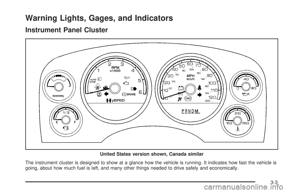
2009 GMC YUKON HYBRID instrument cluster
[x] Cancel search: instrument clusterPage 14 of 94

Automatic Transmission Operation
The vehicle has an electronic shift position indicator
within the instrument panel cluster.
There are several different positions for the shift lever.
See “Range Selection Mode” later in this section.
P (Park):This position locks the rear wheels. It is the
best position to use when you start the engine because
the vehicle cannot move easily.
When parked on a hill, especially when the vehicle
has a heavy load, you may notice an increase in the
effort to shift out of P (Park). See “Shifting Into P (Park)”
in the Index of vehicle’s owner manual for more
information.{CAUTION:
It is dangerous to get out of the vehicle if the shift
lever is not fully in P (Park) with the parking brake
firmly set. The vehicle can roll.
Do not leave the vehicle when the engine is
running unless you have to. If you have left the
engine running, the vehicle can move suddenly.
You or others could be injured. To be sure the
vehicle will not move, even when you are on fairly
level ground, always set the parking brake and
move the shift lever to P (Park). See Shifting Into
Park in the Owner Manual. If you are pulling a
trailer, seeTowing a Trailer on page 4-2.
2-6
Page 19 of 94

Climate Controls..............................................3-2
Warning Lights, Gages, and Indicators..............3-3
Instrument Panel Cluster.................................3-3
Tachometer...................................................3-4
Charging System Light....................................3-4
Fuel Economy Gage.......................................3-5
Brake System Warning Light............................3-6
Antilock Brake System (ABS) Warning Light.......3-7
StabiliTrak
®Indicator Light...............................3-7Engine Coolant Temperature Gage...................3-8
Oil Pressure Gage..........................................3-8
Oil Pressure Light.........................................3-10
Fuel Gage...................................................3-11
Driver Information Center (DIC).......................3-12
DIC Warnings and Messages.........................3-12
Audio System(s).............................................3-14
Navigation/Radio System...............................3-14
Section 3 Instrument Panel
3-1
Page 21 of 94

Warning Lights, Gages, and Indicators
Instrument Panel Cluster
The instrument cluster is designed to show at a glance how the vehicle is running. It indicates how fast the vehicle is
going, about how much fuel is left, and many other things needed to drive safely and economically.United States version shown, Canada similar
3-3
Page 30 of 94

Driver Information Center (DIC)
Trip/Fuel Menu Items
Press the trip/fuel button to display the battery voltage.
For more items see “DIC Operation and Displays” in
the owner manual.
BATTERY VOLTAGE
This display shows the current battery voltage. If the
voltage is in the normal range, the value will display.
For example, the display may read BATTERY
VOLTAGE 13.2 VOLTS. If the voltage is low, the
display will show LOW. If the voltage is high, the display
will show HIGH. Your vehicle’s charging system
regulates voltage based on the state of the battery.
The battery voltage may fluctuate when viewing this
information on the DIC. This is normal. See “Charging
System Light” in the owner manual for more information.
If there is a problem with the battery charging system,
the DIC will display a message. SeeDIC Warnings
and Messages on page 3-12.
INST (Instantaneous) ECONOMY
This display normally shows instantaneous fuel
economy. When the vehicle is in Auto Stop mode
AUTO STOP will be displayed. SeeStarting the
Vehicle on page 2-3for more information. The display
may also show if the vehicle is currently in V4 MODE
or V8 MODE. See “Active Fuel Management” in
the owner manual for more information.
DIC Warnings and Messages
Warning messages are displayed on the DIC to notify
the driver that the status of the vehicle has changed and
that some action may be needed by the driver to
correct the condition. If there is more than one message
that needs to be displayed they will appear one after
another. Some messages may not require immediate
action but you should press the select button or the trip
odometer reset stem on the instrument panel cluster
to acknowledge that you received the message
and clear it from the display. Some messages cannot
be cleared from the display because they are more
urgent; these messages require action before they can
be removed from the DIC display. The following are
the possible messages that can be displayed and some
information about them. For information on other DIC
messages, see “DIC Warnings and Messages” in
the owner manual Index.
3-12
Page 31 of 94

SERVICE BATTERY CHARGING
SYSTEM
If the hybrid battery system faults or fails this message
will appear on the DIC. The engine auto stop feature
will be disabled and the battery/charging system light will
appear in the instrument panel cluster. See “Battery
Warning Light” in the owner manual Index.
Driving with this light on could drain your batteries.
Have the electrical system checked as soon as possible.
Pressing the select button or the trip odometer reset
stem on the instrument panel cluster will acknowledge
this message and clear it from the DIC display.
HOOD OPEN
If the hood is not fully closed or there is a problem
with the hood switch, this message will be displayed.
Close the hood to clear the message. If the HOOD
OPEN message continues to be displayed after
verifying the hood is closed, you should have the hood
switch serviced. Pressing the select button or the
trip odometer reset stem on the instrument panel cluster
will acknowledge this message and clear it from the
DIC display.
When this message is displayed, the auto stop
function will not operate. If the vehicle is in auto stop
mode when this message appears, the engine will
instantly start.
OIL PRESSURE LOW STOP ENGINE
If engine oil pressure is low, this message will be
displayed on the DIC. Stop the vehicle as soon as safely
possible and do not operate it until the cause of the
low oil pressure has been corrected. Check your oil level
as soon as possible and have your vehicle serviced.
See “Engine Oil” in the owner manual Index.
SERVICE BRAKE SYSTEM
This message will be displayed if there is a problem
with the brake system. You will still be able to brake, but
it will be noticeably more difficult. Pull off the road to a
safe location and have your vehicle towed to the nearest
dealer/retailer for service. See “Brakes,” “Brake System
Warning Light,” and “ABS Brake System Warning
Light” in the owner manual Index.
SERVICE HYBRID SYSTEM
If this message is displayed on the DIC, the vehicle may
continue to operate, but you need to have it serviced
as soon as possible.
SERVICE POWER STEERING
This message displays if a problem has been detected
with the electric power steering. Have your vehicle
serviced by your dealer/retailer immediately.
3-13
Page 61 of 94

How to Check
Use a good quality pocket-type gage to check tire
pressure. You cannot tell if your tires are properly
inflated simply by looking at them. Radial tires may look
properly inflated even when they’re underinflated.
Check the tire’s inflation pressure when the tires are cold.
Cold means your vehicle has been sitting for at least
three hours or driven no more than 1 mile (1.6 km).
Remove the valve cap from the tire valve stem.
Press the tire gage firmly onto the valve to get a
pressure measurement. If the cold tire inflation pressure
matches the recommended pressure on the tire and
loading information label, no further adjustment is
necessary. If the pressure is low, add air until you
reach the recommended amount.
If you overfill the tire, release air by pushing on the
metal stem in the center of the tire valve. Recheck the
tire pressure with the tire gage.
Be sure to put the valve caps back on the valve stems.
They help prevent leaks by keeping out dirt and moisture.
Tire Pressure Monitor Operation
This vehicle may have a Tire Pressure Monitor System
(TPMS). The TPMS is designed to warn the driver
when a low tire pressure condition exists. TPMS sensors
are mounted onto each tire and wheel assembly.
The TPMS sensors monitor the air pressure in the
vehicle’s tires and transmit the tire pressure readings
to a receiver located in the vehicle.
When a low tire pressure
condition is detected, the
TPMS will illuminate
the low tire pressure
warning symbol located
on the instrument
panel cluster.
At the same time a message to check the pressure in a
specific tire appears on the Driver Information Center
(DIC) display. The low tire pressure warning light
and the DIC warning message come on at each ignition
cycle until the tires are inflated to the correct inflation
pressure. Using the DIC, tire pressure levels can
be viewed by the driver. For additional information and
details about the DIC operation and displays seeDIC
Warnings and Messages on page 3-12. Also, see “DIC
Operation and Displays” in the Index of the owner
manual for more information.
5-25
Page 92 of 94

F
Flat Tire........................................................5-30
Fluid, Power Steering......................................5-11
Fuel
Gage .........................................................3-11
Fuel Economy Gage......................................... 3-5
G
Gage
Engine Coolant Temperature........................... 3-8
Fuel..........................................................3-11
Fuel Economy.............................................. 3-5
Oil Pressure................................................. 3-8
Tachometer.................................................. 3-4
H
High Voltage Devices and Wiring........................ 5-3
I
Inflation - Tire Pressure...................................5-24
Inflator Kit, Tire.......................................5-32, 5-42
Instrument Panel Cluster................................... 3-3
Introduction........................................................ iii
J
Jump Starting.................................................5-16
L
Light
Antilock Brake System (ABS) Warning.............. 3-7
Brake System Warning................................... 3-6
Charging System........................................... 3-4
Oil Pressure...............................................3-10
StabiliTrak
®Indicator..................................... 3-7
Lumbar
Manual Controls............................................ 1-2
2